Language selection

Search

Patent 2816792 Summary

Third-party information liability

Some of the information on this Web page has been provided by external sources. The Government of Canada is not responsible for the accuracy, reliability or currency of the information supplied by external sources. Users wishing to rely upon this information should consult directly with the source of the information. Content provided by external sources is not subject to official languages, privacy and accessibility requirements.

Claims and Abstract availability

Any discrepancies in the text and image of the Claims and Abstract are due to differing posting times. Text of the Claims and Abstract are posted:

  • At the time the application is open to public inspection;
  • At the time of issue of the patent (grant).
(12) Patent Application: (11) CA 2816792
(54) English Title: TETHER PLATE
(54) French Title: PLAQUE DE FIXATION
Status: Dead
Bibliographic Data
(51) International Patent Classification (IPC):
  • A61B 17/80 (2006.01)
  • A61B 17/88 (2006.01)
  • A61F 2/28 (2006.01)
(72) Inventors :
  • KARAMI, MOHSEN (Canada)
(73) Owners :
  • MOTAMEDI, JOHANBAKHSH JOHN (Canada)
(71) Applicants :
  • MOTAMEDI, JOHANBAKHSH JOHN (Canada)
(74) Agent: NA
(74) Associate agent: NA
(45) Issued:
(22) Filed Date: 2013-04-12
(41) Open to Public Inspection: 2014-10-12
Availability of licence: N/A
(25) Language of filing: English

Patent Cooperation Treaty (PCT): No

(30) Application Priority Data: None

Abstracts

English Abstract


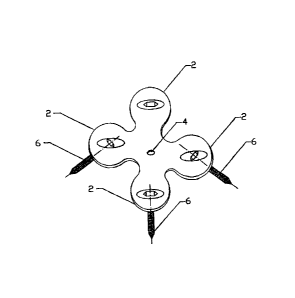
Tether Plate, as depicted in Fig. 1, is a medical device used for limiting
abnormal
growth of a bone growth plate in children. The Tether Plate is composed of a
centre section (1) in the centre of which a small hole (4) is located. It has
four
extensions (2) in which four holes (3) are located and through which four
screws
(6) could be inserted. The distances between two holes (3) are different for
children under the age of 10 and the adolescents. The four holes (3) are
smoothly
tapered and bevelled (5) so that the screws (6) could be inserted in multi-
directions
as decided by a surgeon and as depicted in Fig 3.


Claims

Note: Claims are shown in the official language in which they were submitted.


Claims
1. The device is composed of a centre section (1) in the centre of which a
small
hole (4) is located. It has four extensions (2) in which four holes (3) are
located through which four screws (6) could be inserted. The four holes (3)
are smoothly tapered and bevelled (5).
2. The device according to Claim 1, wherein the center section (1) has the
diameter of 12 mm.
3. The device according to Claim 1, wherein the center section (1) has a
central
hole (4).
4. The device according to Claim 1, wherein the centre hole (4) has the
diameter of 1.5 mm.
5. The device according to Claim 1, wherein the center hole (4) accepts a 0.8
mm temporary guide pin inserted into the growth plate.
6. The device according to Claim 1, wherein there are four extensions (2)
diagonally attached to center section (1).
7. The extensions according to Claim 6, wherein said extensions have an
outside diameter of 11 mm.
8. The extensions according to Claim 6, wherein said extensions have central
holes (3).
9. The Central holes according to Claim 8, wherein said central holes (3) are
tapered with the diameter of 6 mm.
10.The Central holes according to Claim 8, wherein said central holes (3) have

inside diameter of 4.2 mm.
11.The Central holes according to Claim 8, wherein said central holes (3) are
bevelled on the bottom side of the device at 30°.
12.The device according to Claim 1, wherein the heads of the screws (6) are
tapered.
Page 1

13. The device according to Claims 9 and 12, wherein the screws (6) could be
inserted in holes (3) in multi directions so that the center axis of each
screw
(6) is not fixed.
14.The device according to Claim 13, wherein central axis of the four screws
(6) do not converge to a single point.
15.The device according to Claims 2 through 14, wherein the device would
bend according to the shape of the bone's surface and remains fixed via four
screws (6).
16.The device according to Claim 1, wherein the vertical distance between each

two holes (3) 14 mm for children under the age of 10 years.
17.The device according to Claim 1, wherein the vertical distance between each

two holes (3) is 16 mm for adolescent.
18.The device according to Claim 1, wherein the thickness of the plate is 2
mm.
19. The device according to Claims 1 through 18, wherein provides a uniform
tether effect on a wider area and the shape of the bone's growth plate.
20. The device according to Claim 19, wherein prevents asymmetric growth
inhibition even when the device is installed slightly eccentric in the
horizontal direction.
Page 2

Description

Note: Descriptions are shown in the official language in which they were submitted.


CA 02816792 2013-04-12
Description
Field of the Invention: The Tether Plate with its two extensions (2) on each
side,
which can accept 4mm screws (6) through the holes (3), would provide a
temporary physical growth arrest in a child's growing bone. By using this
Tether
Plate, an Orthopaedic surgeon can do a guided inhibition of the growth plate.
Background: Interest in mechanical disruption of abnormal physical growth of
bone is as old as the concept of permanent surgical of epiphysiodesis. Similar

devices and materials, such as Wire by Haas [a], Staples (one to three) by
Blount
[c], and Trans-Physical Screw by Metaizeau et al [b], have been used to
shorten a
bone growth or correct its angulations. But, many complications, such as
implant
failure (wire breakage, staple extrusion or breakage), recurrence of
deformity, and
inadvertent angular deformity because of eccentric insertion of staples or
screws
[d-g] have been reported in literatures.
Recently, a new method by using an 8 like plate has been reported by Stevens
et al
(7). This plate affords only a point like tether on the physics and, if
inserted
eccentrically, there could be a theoretical risk of undesired guided growth
associated with it.
Similarly, the X-Plate by Beutter et al [h] was invented for fracture
fixation. It
lacks a central hole and since the plate has a slight curvature towards its
inside, the
screws converge to a single point. This significantly limits an Orthopaedic
surgeon's flexibility and makes it very difficult for the surgeon to precisely
locate
and install the plate.
Summary of the Invention: Unlike the above mentioned similar devices, the
described Tether Plate spreads the point area of tether effect to a wider area
and
eliminates the possibility of some iatrogenic complications. As a result, the
same
results would be achieved regardless whether the Tether Plate is installed on
slightly posterior or anterior aspects of the growth plate.
The central hole (4) provides the surgeon with the ability to precisely locate
the
Tether Plate over the bone growth plate and the multi-directionality of the
holes (3)
ensures the screws (6) are inserted parallel to the growth plate, as opposed
to
converging to a point.
Page 1 of 3

CA 02816792 2013-04-12
BRIEF DESCRIPTION OF THE DRAWINGS
Having thus described the invention, reference will now be made to the
attached
drawings, which are not necessarily drawn to scale:
Fig 1 shows schematically a top view of the Tether Plate identifying different

sections of the Plate.
Fig 2 shows a cross section of the Tether Plate and its different sections.
Fig 3 shows an isometric view of the Tether Plate and its different sections.
DETAILED DESCRIPTION OF PREFERRED DRAWING
The plate is composed of four identical extensions (2), as shown in Fig 1,
which
I are attached to the central body (1). Each extension has a 4mm smoothly
tapered
and bevelled holes (4-5) via which fixation of the Tether Plate to the bone
through
four screws (6) could be done(Fig 3). The width of the extensions is 11 mm
with a
3006 mm radius filleted steep around the hole, as shown in Fig 2. The central
body
(1) of the Tether Plate is 12 mm in diameter and has a central hole of 1.5 mm.
The
central hole can take a 0.8 mm guide pin, which can be used to locate the mid
antero-posterior point of the growth plate under fluoroscopic control. The
center to
center vertical distance between two holes (2) is 16 mm for adolescent and 14
mm
for children 10 years old and under. The thickness of the plate is 2 mm, as
shown
in Fig 2.
Page 2 of 3
Representative Drawing
A single figure which represents the drawing illustrating the invention.
Administrative Status

For a clearer understanding of the status of the application/patent presented on this page, the site Disclaimer , as well as the definitions for Patent , Administrative Status , Maintenance Fee  and Payment History  should be consulted.

Administrative Status

Title Date
Forecasted Issue Date Unavailable
(22) Filed 2013-04-12
(41) Open to Public Inspection 2014-10-12
Dead Application 2016-04-13

Abandonment History

Abandonment Date Reason Reinstatement Date
2015-04-13 FAILURE TO PAY APPLICATION MAINTENANCE FEE

Payment History

Fee Type Anniversary Year Due Date Amount Paid Paid Date
Application Fee $200.00 2013-04-12
Owners on Record

Note: Records showing the ownership history in alphabetical order.

Current Owners on Record
MOTAMEDI, JOHANBAKHSH JOHN
Past Owners on Record
None
Past Owners that do not appear in the "Owners on Record" listing will appear in other documentation within the application.
Documents

To view selected files, please enter reCAPTCHA code :


To view images, click a link in the Document Description column. To download the documents, select one or more checkboxes in the first column and then click the "Download Selected in PDF format (Zip Archive)" or the "Download Selected as Single PDF" button.

List of published and non-published patent-specific documents on the CPD .

If you have any difficulty accessing content, you can call the Client Service Centre at 1-866-997-1936 or send them an e-mail at CIPO Client Service Centre.


Document
Description 
Date
(yyyy-mm-dd) 
Number of pages   Size of Image (KB) 
Description 2013-04-12 2 92
Claims 2013-04-12 2 67
Drawings 2013-04-12 1 11
Abstract 2013-05-15 1 17
Representative Drawing 2014-09-29 1 4
Cover Page 2014-10-27 1 32
Office Letter 2017-06-14 1 35
Refund 2017-06-16 1 21
Refund 2017-06-22 1 37
Correspondence 2013-06-07 1 16
Correspondence 2013-06-07 2 39
Correspondence 2013-06-07 1 23
Correspondence 2013-06-07 1 14
Assignment 2013-04-12 7 139
Prosecution-Amendment 2013-04-12 3 65
Correspondence 2013-05-15 2 30
Request for Examination 2016-04-11 1 129
Office Letter 2016-04-22 1 26
Fees 2016-04-11 1 130
Correspondence 2016-06-13 1 25
Maintenance Fee Correspondence 2016-11-07 2 53
Prosecution Correspondence 2016-11-07 2 53