Note: Descriptions are shown in the official language in which they were submitted.
CA 02817075 2013-05-06
WO 2012/064698
PCT/US2011/059716
INDUCTION WELDED WATERPROOFING
CROSS-REFERENCE TO RELATED APPLICATION
[0001] The
benefit under 35 U.S.C. 119(e) of U.S. Provisional Patent Application Serial
No. 61/411,002 filed November 8, 2010, is hereby claimed, and its entire
disclosure is
incorporated herein by reference.
FIELD OF DISCLOSURE
[0002] The present disclosure is applicable to sub-grade waterproofing,
preferably the
formation of a self-healing waterproof barrier prior to the pouring or
placement of the
structural element to be waterproofed.
BRIEF DESCRIPTION OF RELATED TECHNOLOGY
[0003] Traditionally, the membrane is welded to thermoplastic fixing anchors
placed over
the cushion/drainage layer(s); then the thermoplastic membrane waterproofing
sheets are
welded to the fixing anchors with hand held air welding equipment. This
requires the installer
to get behind the suspended membrane from the top, bottom or sides of the
suspended
sheets in order to access the fixing anchors to weld them to the thermoplastic
waterproofing
membrane. There are other non-penetrating methods however; all require access
to the
back side of the membrane. This step is not only time consuming but can be
dangerous,
especially when working on scaffolding and or in confined space.
SUMMARY OF INVENTION
[0004] Attaching membrane waterproofing to shoring in a manner that does not
penetrate
the waterproofing membrane has several traditional solutions that favor small
membrane
sheet or panel sizes. Large prefabricated or factory fabricated panels pose
challenges that
require additional steps and or equipment. These additional steps reduce
installation
efficiency and combined with the additional equipment increase installation
cost. Placing
large prefabricated panels on large shoring walls requires access behind the
waterproofing
membrane panels. Typically, this requires lifting a panel that is affixed at
the top, from the
bottom and allowing it to drape down to available fastening tabs. This step
greatly increases
the time required for operating the equipment used to suspend the membrane
panels;
typically a crane or lift of some type. Alternately, another method requires
access to the back
side of the membrane to weld the thermoplastic membrane to thermoplastic
fastening discs.
Bored rock tunnels additionally challenge typical membrane installation
methods due to the
confined space and inverted arch configuration of the structure. Unique to all
other
waterproofing applications, a bored rock tunnel is the only type of
waterproofing that requires
1
CA 02817075 2013-05-06
WO 2012/064698 PCT/US2011/059716
fixing the waterproofing membrane to overhead shoring; and specifically to a
shoring surface
with a closing radius.
BRIEF DESCRIPTION OF THE DRAWING FIGURES
[0005] Figure 1 is a cross-section of a water-proofing laminate against a
hydraulic source
in accordance with an embodiment of the disclosure;
[0006] Figure 2 is a cross-section of a water proofing laminate having self-
healing
hydraulic barrier in accordance with an embodiment of the disclosure;
[0007] Figures 3A-3C are three cross-sections of embodiments of a fastener
integrated
drainboard in accordance with an embodiment of the disclosure and Figure 3D is
a
schematic drawing of an external view of a fastener integrated drainboard in
accordance
with an embodiment of the disclosure;
[0008] Figure 4 is a schematic drawing of a water-proofing laminate in
accordance with
the disclosure used to water-proof the internal area of a bored rock tunnel;
[0009] Figure 5 is a schematic drawing of fastening plate portion of water-
proofing
laminate in accordance with an embodiment of the disclosure in a bored rock
tunnel;
[0010] Figure 6 is an enlarged schematic drawing of the fastening plate
portion of Figure
5;
[0011] Figure 7 is a schematic drawing of a reinforcement positioned
through a self-
healing waterproofing laminate and optional water-proofing elements in
accordance with an
embodiment of the disclosure;
[0012] Figures 8A-8F illustrate examples of salt-water swellable materials
and methods of
manufacture, in accordance with an embodiment of the disclosure;
[0013] Figure 9 is a graph illustrate the SAP welling in salt water of
hydraulic barrier in
accordance with an embodiment of the disclosure;
[0014] Figure 10A is a schematic drawing illustrating an apparatus and
method of
manufacturing a hydraulic barrier in accordance with an embodiment of the
disclosure;
[0015] Figures 10B-10D are cross-sectional images of the hydraulic barrier
at different
points of the method of manufacturing illustrated in Figure 10A;
[0016] Figure 11 is a schematic drawing illustrating an apparatus and
method of
manufacturing a hydraulic barrier in accordance with an embodiment of the
disclosure; and
[0017] Figure 12 is a schematic drawing illustrating a placement of a
hydraulic barrier in
accordance with an embodiment of the disclosure.
2
CA 02817075 2013-05-06
WO 2012/064698
PCT/US2011/059716
DETAILED DESCRIPTION OF THE INVENTION
[0018] The present invention may be understood more readily by reference to
the
following detailed description of the invention and the examples provided
therein. It is to be
understood that this invention is not limited to the specific components,
articles, processes
and/or conditions described, as these may, of course, vary. It is also to be
understood that
the terminology used herein is for the purpose of describing particular
embodiments only and
is not intended to be limiting.
[0019] Ranges may be expressed herein as from "about" or "approximately" one
particular
value and/or to "about" or "approximately" another particular value. When such
a range is
expressed, another embodiment includes from the one particular value and/or to
the other
particular value. Similarly, when values are expressed as approximations, by
use of the
antecedent "about," it will be understood that the particular value forms
another embodiment.
[0020]
Herein is described materials and methods of water-proofing a structural
feature
from a hydraulic source, preferably wherein the hydraulic source is sub-grade
(below
ground). Examples of sub-grade hydraulic sources include retaining walls,
shoring walls;
unlined rock walls and tunnels; and porous cement (e.g., shotcrete coatings)
that are in
contact with ground water and, preferably, are at or below the water table.
Typically, the
hydraulic source is a sub-grade structure through which ground-water can flow.
Further
examples, include cut or excavated rock walls, bored rock tunnels, excavated
soil,
foundation backfill, the retaining and/or shoring walls erected to prevent
collapse of an
excavated area.
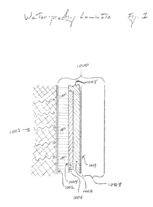
[0021] The following reference numbers correspond to Figures 1-7.
[0022] In a
first embodiment, a water-proofing laminate 1000 includes a drainboard 1001
having a first surface 1002 positioned against a hydraulic source 1003 and a
second surface
1004 opposed to the first surface; a fastener plate 1005 positioned against
the second
surface 1004 of the drainboard 1001 securing the drainboard 1001 to the
hydraulic surface
1003, the fastener plate 1005 comprising a conductive element 1006 and a
thermoplastic
resin 1007; and a self-healing hydraulic barrier 1008 comprising a
thermoplastic surface
1009 adjoined to a geotextile and carrying a water-absorbent material, the
thermoplastic
surface 1009 inductively welded to the fastener plate. Furthermore, the
drainboard can be
secured to the hydraulic source by a fixing member (e.g., a mechanical
fastener) where at
least a portion of a fixing member passes through the fastener plate and the
drainboard and
into the hydraulic source.
[0023] A drainboard is a drainage material, preferably including a geotextile
through which
water can flow. The drainboard can include the geotextile or can be entirely
the geotextile.
Examples of drainboards that include geotextiles include, but are not limited
to,
3
CA 02817075 2013-05-06
WO 2012/064698 PCT/US2011/059716
AQUADRAIN products, for example product numbers G20, 10X, 15X, 15XP, 18H, 20H,
30H,
G20, and 100BD (all available from CETCO, Hoffman Estates, IL); GEOTEX 3201
and
GEOTEX 1701 (available from PROPEX GEOSYNTHETICS, Chattanooga, TN). In all
applications of a drainboard the geotextile is positioned against the
hydraulic source.
[0024] Drainboards can further include drainage cores adhered to the
geotextile. A
drainage core can be a three dimensional, preferably water impervious,
material having
support columns and drainage areas, herein called a dimple core. The
geotextile is bonded
to the support column, functions in part as a particulate filter, and defines
an interior
drainboard space where drainage or flow of water can occur. Alternatively, the
drainage core
can be a geonet, in one example the geonet can be positioned between layers of
the
geotextile. Typically, drainboards are positioned in locations wherein the
hydraulic source
supplies a hydraulic force on the drainboard, preferably on the water
permeable geotextile
portion.
[0025] Herein, a fastener plate includes a conductive element and a
thermoplastic resin.
Preferably the fastener plate consists essentially of a plate-like main member
made from the
thermoplastic resin, and a conductive sheet made of the conductive element
that is adhered
to the main member. In one example, the conductive sheet can be provided as a
layer within
the plate-like main member. In another example, the fastener plate can include
a conductive
support having a securing surface, a welding surface, and comprising the
conductive
element where the welding surface is carrying the thermoplastic resin.
Multiple examples of
fastener plates are available commercially, examples are represented in U.S.
Patent Nos.
6,640,511 and 6,338,232, the entire disclosures of which are incorporated
herein by
reference.
[0026] The self-healing hydraulic barrier 1008 can include a thermoplastic
surface 1009
adjoined to a geotextile 1011 and carrying a water-absorbent material 1012.
The
thermoplastic surface 1009 is preferably carried by a thermoplastic layer 1010
that is more
preferably a water-impermeable layer. The thermoplastic, water-impermeable
layer 1010 is
adhered to the geotextile 1011. For example the thermoplastic layer can
include an adhesive
layer 1013 that binds to the geotextile, the adhesive layer can further adhere
the water-
absorbent material. In one example, the self-healing hydraulic barrier carries
the water-
absorbent material between the thermoplastic surface and the geotextile, for
example, the
water-absorbent material can be adhered to the thermoplastic layer. In another
example the
geotextile is impregnated with the water-absorbent material. In another
example, the self-
healing hydraulic barrier includes the thermoplastic layer, a water-absorbent
layer, and the
geotextile; where the water-absorbent layer adheres the geotextile to the
thermoplastic layer.
4
CA 02817075 2013-05-06
WO 2012/064698 PCT/US2011/059716
[0027] The water-absorbent material of the self-healing hydraulic barrier can
be selected
from the group consisting of a super-absorbent polymer, a clay, and a mixture
thereof. In
one embodiment, the water-absorbent material can be a salt-water swellable
composition.
One example of a salt-water swellable composition includes about 30 wt. % to
about 60 wt.
% of a smectite clay; about 5 wt. % to about 25 wt. % of a partially cross-
linked
acrylamide/partially neutralized acrylic acid copolymer; about 3 wt. % to
about 15 wt. % of at
least one elastomeric resin; about 5 wt. % to about 30 wt. % of a cationic
flocculant; and
about 0.5 wt. % to about 25 wt. % of at least one primary plasticizing agent
for the
elastomeric resin.
[0028] In one embodiment of the self-healing hydraulic barrier, the self-
healing hydraulic
barrier described is based on the discovery that agricultural grade
superabsorbent polymers
partially cross-linked (water insoluble) copolymers of acrylamide/partially
neutralized acrylic
acid, particularly potassium and/or sodium acrylate, have exceptional and
unexpected free
swell when in contact with high conductivity water or multivalent ion-
containing-contaminated
water The self-healing hydraulic barrier can include a partially cross-linked
acrylamide/acrylate/acrylic acid copolymer and are used for waterproofing
against high
conductivity salt-containing water. More particularly, the partially cross-
linked
acrylamide/acrylate/acrylic acid copolymers, are incorporated into sheet or
roll form as
waterproofing geotextile articles; or are incorporated into deformable, putty-
like consistency
articles for waterproofing concrete joints and the like (see U.S. Patent No.
4,534,926, hereby
incorporated by reference) by substituting the agricultural grade SAPs
described herein for
the bentonite clay disclosed in U.S. Pat. No. 4,534,926. The sheet or roll
form geotextile
articles of manufacture described herein are self-healing (will seal cuts,
cracks and fissures
caused in adjacent water barrier sheets or films during or after installation)
and are
particularly effective in sealing seems between two water barrier substrates,
e.g., concrete
sections and between adjacent, geocomposite liners in contact with high
conductivity salt
water.
[0029] The self-healing hydraulic barrier is preferably a multi-layer
geocomposite article
that can include a polymeric barrier layer, a woven or non-woven layer, and an
intermediate
layer of a partially cross-linked acrylamide/acrylate/acrylic acid copolymer
that has sufficient
free-swell when contacted by high conductivity water such that if a crack or
rupture occurs in
the polymeric barrier layer, the confined copolymer will swell sufficiently
upon salt water
contact to fill the crack or rupture to heal the crack or rupture and prevent
further salt water
leakage.
[0030] In another embodiment, the water-proofing laminate can include a
hydraulic
surface exposed to a hydraulic source and carried by a drainboard; the
drainboard held in a
CA 02817075 2013-05-06
WO 2012/064698 PCT/US2011/059716
fixed position by a fastener plate; and the fastener plate welded to a
thermoplastic surface
carried by a shelf-healing hydraulic barrier.
[0031] In yet another embodiment, the water-proofing laminate can include a
hydraulic
surface carried by a drainboard; a dry surface carried by a self-healing
hydraulic barrier; and
positioned between the hydraulic surface and the dry surface; a fastener plate
affixed to the
drainboard and welded to a self-healing hydraulic barrier.
[0032] In still another embodiment, the water-proofing laminate can include
a plurality of
fastener plates individually comprising a conductive element and a
thermoplastic resin; and
a self-healing hydraulic barrier comprising a thermoplastic layer adjoined to
a geotextile and
carrying a water-absorbent material; wherein the self-healing hydraulic
barrier is adjoined to
the plurality of fastener plates by a plurality of induction welds formed
between the
thermoplastic layer and the thermoplastic resin. Typically, the induction weld
includes three
heat effected zones: a fastener plate zone, a fusion zone, and a self-healing
hydraulic barrier
zone. Preferably, the fastener plate zone has a volume larger than the
individual volumes of
either the fusion zone or the self-healing hydraulic barrier zone.
Additionally, the fastener
plate zone is preferably approximately coextensive with the volume of the
thermoplastic
resin, that is, preferably, the entire thermoplastic resin is heated during
the welding process
and forms the fastener plate (heat effected) zone.
[0033] Further presented herein is a method of preparing a water-proofing
laminate. The
method can include positioning a thermoplastic surface of a self-healing
hydraulic barrier
against a fastening plate secured to a hydraulic source; and then inductively
welding the
thermoplastic surface and the fastening plate. The method can further include
securing the
fastening plate to the hydraulic source. For example, securing the fastening
plate to the
hydraulic source by passing a fixing member through the fastener plate and
into the
hydraulic source. The fixing member can be selected from those mechanical
fasteners
capable of holding the fastening plate to the hydraulic source, these include
concrete
fasteners, screws, drive pins, and nails. The method can further include
positioning a
drainboard between the hydraulic source and the fastening plate; and then
securing the
fastening plate to the hydraulic source with the fixing member by passing a
fixing member
through the fastener plate and drainboard and into the hydraulic source. The
method can still
further include sealing any seams between overlapping or abutting layers of
the self-healing
hydraulic barrier, for example between overlapping layers of the thermoplastic
surface.
[0034] In another embodiment the method includes fixing a fastening plate
to a hydraulic
source by, for example, powder actuating or pneumatic actuating a fixing
member through
the fastener plate; and then inductively welding a self-healing hydraulic
barrier to the
fastening plate. The powder actuating can be accomplished by employing, for
example, a
6
CA 02817075 2013-05-06
WO 2012/064698 PCT/US2011/059716
powder-actuated nail gun, multiple examples of which are commercially
available. Similarly,
pneumatic actuating can be accomplished by employing, for example, a pneumatic
nail or
screw gun, multiple examples of which are commercially available.
[0035] In yet another embodiment, the method can be a method of waterproofing
a tunnel
that includes positioning a drainage material against a tunnel wall and/or
ceiling, the
drainage material having a first surface positioned against the tunnel wall
and/or ceiling and
a second surface exposed; attaching the drainage material to the tunnel wall
and/or ceiling
with a plurality of fastener plates and fixing members extending through the
fastener plates
and the drainage material and adhered to the tunnel wall and/or ceiling, the
fastener plates
comprising a conductive element and a thermoplastic resin; and inductively
welding a self-
healing hydraulic barrier to the fastener plates, the self-healing hydraulic
barrier comprising a
water-impermeable thermoplastic layer adjoined to a water-absorbent material
and a
geotextile.
[0036] The method of waterproofing a tunnel can also include applying
shotcrete against
bored rock in a tunnel to form a smoothed tunnel wall and/or ceiling; and
curing the
shotcrete; where the drainage material is positioned against the smoothed
tunnel wall and/or
ceiling. Still further, the method of waterproofing a tunnel can include
applying concrete
against the geotextile to form a interior tunnel wall and/or ceiling; and
curing the concrete.
Additionally, the method of waterproofing a tunnel can include applying a
water-stop to all
concrete joints.
[0037] Dependant on the flow characteristics of the tunnel design, the
method of
waterproofing the tunnel can include positioning the drainage material against
the tunnel
floor, the drainage material have a first surface positioned against the
tunnel floor and a
second surface exposed; and covering the drainage material with the self-
healing hydraulic
barrier by positioning the water-impermeable thermoplastic layer against the
drainage
material. In circumstances where waterproofing is not applied to the floor of
the tunnel, a
pump system can be installed to remove water that may enter the tunnel through
the
unwaterproofed area.
[0038] In still another embodiment, the method can be a method of applying a
water-
proofing laminate to a retaining and/or shoring wall that includes positioning
a drainage
material against the retaining and/or shoring wall, the drainage material have
a first surface
positioned against the retaining and/or shoring wall and a second surface
exposed; attaching
the drainage material to the retaining and/or shoring wall with a plurality of
fastener plates
and fixing members extending through the fastener plates and the drainage
material, and
adhered to the retaining and/or shoring wall, the fastener plates comprising a
conductive
element and a thermoplastic resin; and inductively welding a self-healing
hydraulic barrier to
7
CA 02817075 2013-05-06
WO 2012/064698 PCT/US2011/059716
the fastener plates, the self-healing hydraulic barrier comprising a water-
impermeable
thermoplastic layer adjoined to a water-absorbent material and a geotextile.
This method of
waterproofing a retaining wall and/or shoring wall can include applying
concrete against the
geotextile to form a water-proofed sub-grade wall; and curing the concrete;
wherein the
concrete binds to the geotextile.
[0039] A further embodiment of the above disclosed embodiments includes
providing a
structural anchor through the water-proofing laminate. One example of
providing a structural
anchor can include all or fewer steps of providing a mounting hole in the
hydraulic source,
fixing at least a portion of an anchor in the mounting hole (e.g., applying an
epoxy to the
internal surface of the mounting hole), providing a thermoplastic flange over
the anchor and
against the mounting hole and hydraulic source, overlaying the thermoplastic
flange with a
self-healing hydraulic barrier, thermally weld (e.g., hot air weld, induction
weld) a
thermoplastic surface of the self-healing hydraulic barrier to the
thermoplastic flange. The
method can further include overlaying the weld with a patch flange (e.g.,
CORTEX PATCH
available from CETCO, Hoffman Estates, IL); and/or applying sealants to seams
and joints
(e.g., CETSEAL available from CETCO, Hoffman Estates, IL). Preferably, the
anchor
extends from the hydraulic source at sufficient distance to provide for the
attachment of
structural elements (e.g., structural reinforcements) added prior to the
providing of a
concrete against the self-healing hydraulic barrier.
[0040] In still another embodiment, the preceding materials and methods of
waterproofing
a structure can employ a fastener-integrated drainboard. Such a fastener-
integrated
drainboard is a drainboard with a fastener plate adhered thereto. For example,
the fastener-
integrated drainboard can include a water-permeable sheet; and a fastener
plate affixed to
the water-permeable sheet; the fastener plate comprising a thermoplastic
adhesive and a
metal receptor. The fastener plate can be affixed to the water-permeable sheet
by an
adhesive, for example, a pressure sensitive adhesive, a polyurethane adhesive,
an epoxy
adhesive, a silicone adhesive, thermoplastic adhesive; by a clip or a
plurality of clips; by
barbs extending through the water-permeable sheet; or mixtures thereof.
Dependent on the
size of the fastener-integrated drainboard, it preferably includes a plurality
of fastener plates.
For example, the fastener plates can be positioned at regular intervals on the
water-
permeable sheet, for example 3 feet to 4 feet on center. When for example, the
resultant
fastener-integrated drainboard has an area of about 4 feet by greater than 4
feet (often
drainboards are sold as 4'x52' rolls), the fastener plate can be integrated on
center (about
two feet from either edge) and spaced at about 3 to about 4 feet along the
length of the
fastener-integrated drainboard. When, for example, the drainboard is a non-
rolling sheet
material, the fastener plates can be integrated in a regular grid pattern on
the drainboard, for
8
CA 02817075 2013-05-06
WO 2012/064698 PCT/US2011/059716
example, about 1 foot to about 4 foot on center. Alternatively, the spacing of
the fastener
plates can increase as a function, for example distance from an edge.
[0041] One embodiment of preparing the fastener-integrated drainboard can
include fixing
a fastener plate that comprises a metal receptor and a thermoplastic adhesive
to a water-
permeable sheet. Another embodiment of preparing the fastener-integrated
drainboard can
include positioning a metal receptor against a water-permeable sheet; applying
a
thermoplastic adhesive to the metal receptor; and heating the thermoplastic
adhesive to a
sufficient temperature to form a adhesive bond between the metal receptor and
the water-
permeable sheet.
[0042] The fastener-integrated drainboard can be employed in a method that
includes
positioning a fastener-integrated drainboard that comprises a fastener plate
against a
hydraulic source; powder actuating or pneumatic actuating a fixing member to
secure the
fastener-integrated drainboard to the hydraulic source by passing at least a
portion of the
fixing member through the fastener plate; and then inductively welding a self-
healing
hydraulic barrier to the fastener plate. This method can further include those
features
described above.
[0043] Self-healing hydraulic barriers can include the following methods
and materials:
ONE EXAMPLE OF A HYDRAULIC BARRIER
[0044] The disclosure of U.S. Patent No. 6,783,802 is incorporated herein by
reference in
its entirety.
[0045] Referring to the drawing of U.S. Patent No. 6,783,802, the invention
relates to a
hydraulic barrier material. In one embodiment, the hydraulic barrier material
is an
interlocking matrix containing a water-absorbent organic polymer and a water-
absorbent clay
interlocked to and within a liquid monomer-absorbent or liquid monomer-
adsorbent
substrate, wherein the polymer is formed (polymerized from one or more
monomers), in-situ,
while in contact with the substrate during manufacture of the hydraulic
barrier to interlock the
polymer and clay to the substrate. In the preferred embodiment, the hydraulic
barrier
material is an interlocking matrix of organic polymer molecules, polymer-
intercalated clay,
polymer-intercalated clay tactoids, exfoliated clay platelets and fibers of a
fibrous substrate,
preferably a non-woven geotextile. The preferred organic polymer is a water-
absorbent
polymer preferably comprising a mixture of an alkali metal salt of polyacrylic
acid (50-90
mole percent - corresponding to 50-90 mole percent neutralization of acrylic
acid) and
polyacrylic acid (10-50 mole percent). It has been found that the interlocking
of the organic
polymer, polymer-intercalated clay tactoids, and clay platelets to the
substrate provides a
hydraulic barrier material having a relatively low permeability to water while
containing a
relatively low loading of organic polymer.
9
CA 02817075 2013-05-06
WO 2012/064698 PCT/US2011/059716
[0046] It has further been found that the hydraulic barrier material
provides reduced
permeability to water per unit weight of hydraulic barrier material as
compared to
conventional liners or hydraulic barriers, and in particular, geosynthetic
clay liners (GCLs).
Particularly, it has been found that the hydraulic barrier material has a
hydraulic conductivity
of 1x10⁻⁹ cm/sec. or less. Further, it has also been found that the hydraulic
barrier material
has a reduced thickness and a reduced weight as compared with conventional
GCLs, while
achieving better water impermeability. The hydraulic barrier material may be
particularly
suitable for geo-environ mental applications such as water absorption, water
retention and
water containment. For instance, the hydraulic barrier material may have
particular
application for use in below grade water proofing, such as underground parking
garages,
shopping malls and the like to prevent ground water intrusion; waste
landfills; man-made
bodies of water; and other geo-environmental applications where a low
permeability
hydraulic barrier is required. In the preferred embodiment, the organic
polymer is formed
from the polymerization of an organic monomer intercalated into a clay,
preferably a water-
swellable clay. The method of making the hydraulic barrier material includes
the steps of
embedding a polymerizable organic monomer within a liquid-sorbent substrate
after first
applying a polymerization catalyst or polymerization initiator to the liquid-
sorbent substrate,
or to one or more of the component parts of the liquid-sorbent substrate,
e.g., to fibers of
geotextile during the manufacture of the geotextile, and effecting
polymerization of the
polymerizable monomer, in situ, to form the hydraulic barrier material.
[0047] The polymerizable monomer is applied to the polymerization-initiating
substrate
from a polymerization solution that is a slurry of the polymerizable organic
monomer and a
water-swellable clay, such as a sodium smectite clay, particularly a sodium
montmorillonite
or a sodium bentonite clay, to form a slurry that is embedded into the porous
substrate that
has previously been treated, e.g., contacted or dipped or sprayed, to contain
a
polymerization catalyst or polymerization initiator for the organic monomer in
an amount
sufficient to fully polymerize the subsequently embedded monomer. In the
preferred
embodiment, the substrate is loaded with at least 5% by weight polymerization
initiator, or
polymerization catalyst, based on total weight of polymerizable monomer
subsequently
embedded in the substrate from the polymerization solution (polymerization
slurry). More
preferably, the substrate is loaded with at least 10% by weight polymerization
initiator and/or
polymerization catalyst based on the weight of subsequently embedded
polymerizable
monomer.
[0048] The polymerizable monomer preferably is mixed with water 7 and includes
a
neutralizing agent 8, such as sodium hydroxide, preferably prior to the
addition of the clay 9,
to form the polymerization solution in the form of a slurry, in order to more
easily effect
neutralization of least a portion of the polymerizable organic monomer (most
preferably 65-
CA 02817075 2013-05-06
WO 2012/064698 PCT/US2011/059716
85 mole percent neutralization) before clay addition and subsequent
intercalation of the
partially neutralized polymerizable organic monomer into the clay. Preferably,
the
polymerization solution also contains a cross-linking agent for the polymer so
that after
polymerization, the partially neutralized polymer molecules are cross-linked
sufficiently for
water-insolubility and water absorbency. Preferably, the polymerizable
monomer, water,
cross-linking agent, and neutralizing agent are thoroughly mixed to form a
homogeneous
solution prior to adding clay to form the polymerization solution or slurry
for consistency and
homogeneity in intercalation of the clay. In the preferred embodiment, the
polymerization
solution mixing step is performed such that the polymerization solution is
substantially
homogeneous.
[0049] The step of adding clay to the monomer solution to form the
polymerization
solution or polymerization slurry may be performed in any manner that results
in the addition
of a desired amount of the clay and monomer to form a slurry that is
relatively viscous, but is
capable of being moved to the polymerization-initiating substrate for
embedment. In
addition, the polymerization solution containing the clay is preferably
sheared during mixing
and/or sheared while embedding the slurry into the liquid-sorbent or porous
substrate to
intercalate a portion of the polymerizable monomer between clay platelets
prior to
embedding the slurry into the substrate, and preferably to partially exfoliate
the clay platelets
prior to, or simultaneously with, contacting the substrate with the
polymerization solution.
[0050] The degree of mixing of the slurry will vary depending upon the desired
characteristics of the slurry. For instance, the clay may be simply combined
together with
the polymerization solution with no concern regarding the degree of mixing or
homogeneity
of the resulting slurry. Preferably, the mixing step is performed such that
the slurry is mixed
and sheared prior to the subsequent embedding of the slurry into the catalyst-
or initiator-
containing porous substrate. In the preferred embodiment, the mixing step used
to form the
slurry is performed such that the slurry is substantially homogeneous.
[0051] Any mixer 16 and any mixing method may be used which are capable of
mixing the
clay and the monomer to achieve the desired characteristics of the slurry.
Thus, in the
preferred embodiment, any mixer 16 and any mixing process may be used which
are
capable of mixing the clay and the polymerization solution such that the
resulting slurry is
substantially homogeneous. Further, the mixing step may be performed for any
period or
length of time sufficient to achieve the desired characteristics of the
slurry. In the preferred
embodiment, the mixing step is performed for a length of time sufficient to
mix the clay and
the polymerization solution such that the resulting slurry is substantially
homogeneous.
Minimum water is preferably used to obtain a homogeneous slurry, while
producing a slurry
that is capable of being mechanically conveyed or pumped to the substrate for
embedding
the slurry into the substrate. As shown in Fig. 1, in the preferred
embodiment, a piston 32 of
11
CA 02817075 2013-05-06
WO 2012/064698 PCT/US2011/059716
piston pump assembly 30 is used to convey the high viscosity slurry to the
liquid-sorbent
substrate for the embedding step. If the slurry is too viscous for pumping, a
conveyor belt,
preferably having a slurry-covered width that is the same as the substrate,
can be used to
move the slurry to the substrate.
[0052] As indicated above, the monomer embedding step comprises commingling
the
polymerizable organic monomer/clay slurry with the substrate.
[0053] In the preferred embodiment, the slurry is embedded within the
catalyst-containing,
liquid-sorbent substrate at a slurry viscosity of about 30,000 centipoises to
about 80,000
centipoises, more preferably about 40,000 to about 60,000 centipoises, for
absorption and/or
adsorption of the slurry into and/or between the components of the substrate.
The slurry is
received into at least a portion of the thickness of the substrate. Any amount
or degree of
embedding of the slurry into, or between the component parts of the substrate
is acceptable
so long as the embedding of the monomer is sufficient to permit the
commingling and
sorption of the monomer and clay between and/or within the component parts,
e.g., the
fibers of the substrate, for subsequent polymerization of the monomer
internally within at
least a portion of the thickness of the substrate to form the hydraulic
barrier material.
Further, the degree or amount of embedding is sufficient if it permits the
bonding or
interlocking of the resulting absorbent polymer and clay within at least a
portion of the
thickness of the porous substrate.
[0054] Preferably, the embedding step includes combining the substrate, and
the slurry
such that the slurry is distributed uniformly throughout at least a portion of
the thickness of
the substrate. The slurry is preferably well mixed, and more preferably is
substantially
homogeneous, so that combining the slurry and the substrate also results in
the distribution
of the monomer, monomer-intercalated clay, and exfoliated clay platelets
throughout a
desired thickness of the substrate. More preferably, the slurry is distributed
throughout the
entire thickness of the porous substrate in order to facilitate the production
of a relatively
homogeneous hydraulic barrier material.
[0055] As discussed previously, the porous substrate may be any porous
material or
substance compatible with the monomer and any other components contained with
the
polymerization slurry, where applicable. Any porous substrate may be used that
is able to
receive and retain at least a portion of both the polymerization catalyst or
polymerization
initiator, and subsequently the polymerizable monomer(s) and clay to form the
hydraulic
barrier material upon the polymerization of the monomer. More preferably, the
porous
substrate is comprised of a fibrous substrate having a plurality of fibers.
Any fibrous
substrate can be used that is able to form the hydraulic barrier material upon
the
polymerization of the monomer.
12
CA 02817075 2013-05-06
WO 2012/064698 PCT/US2011/059716
[0056] In the preferred embodiment, the substrate is a geotextile material.
Any woven or
non-woven geotextile material may be used, preferably non-woven. Further, the
geotextile
material may be in any form compatible with providing the desired hydraulic
barrier material.
However, in the preferred embodiment, the fibrous substrate is a substantially
planar sheet
comprising at least one layer of geotextile material.
[0057] In the preferred embodiment, the embedding step is comprised of
embedding the
slurry, having a water content of less than 50% by weight, and thus the
monomer and clay,
between the fibers of the initiator- or catalyst-containing fibrous substrate.
The embedding
step may be performed in any manner, and by any apparatus, resulting in the
embedding of
the high viscosity slurry between, and/or absorbed within the component parts,
e.g., fibers,
of the substrate. In other words, the slurry can be embedded or directed
within the interstitial
spaces or voids between and/or absorbed within the fibers of the fibrous
substrate, and/or
may be absorbed by the fibers of the substrate. For instance, the slurry may
be embedded
between the fibers of the fibrous substrate by vacuum, scrubbing, rolling,
hydraulic loading,
pressure filtration or spraying. If the fibers themselves are water-absorbent,
the monomer
will be absorbed into the fibers as well.
[0058] In the preferred embodiment, at least a portion of the slurry is
embedded between
the fibers of the fibrous substrate in the interstitial spaces or voids. The
remainder or
balance of the slurry which is not embedded may be dispersed or spread among
the fibers of
the fibrous substrate or distributed upon or about the fibers to provide a
layer or coating of
the slurry. Any amount or degree of embedment of the slurry between the fibers
of the
substrate, sufficient to permit the subsequent polymerization of the monomer,
is acceptable.
[0059] In the preferred embodiment, the bulk or major fraction or
proportion of the slurry is
embedded in the substrate, while a small or minor fraction or proportion of
the slurry
optionally may be dispersed or distributed on top of the substrate.
Preferably, any slurry that
may be distributed on top of the substrate has a thickness of less than about
2.0 mm, more
preferably less than about 1.0 mm, most preferably less than about 0.50 mm.
[0060] Further, in the preferred embodiment, the slurry is embedded between
the fibers of
the fibrous substrate by applying a compressive force to the fibrous
substrate. The
compressive force is preferably applied in a direction substantially
perpendicular to the plane
of the fibrous substrate, as discussed further below. The compressive force
may be applied
in any manner, and by any method, or apparatus that results in the desired
degree or
amount of embedding of the slurry between the fibers of the fibrous substrate.
[0061] For instance, the compressive force may be applied to the fibrous
substrate with at
least one pair of pressure rollers 18 as shown in Figure 1. In addition, the
compressive force
may be applied to the fibrous substrate using a vacuum.
13
CA 02817075 2013-05-06
WO 2012/064698 PCT/US2011/059716
[0062] Following the embedding step, the process comprises the step of
effecting the
polymerization of the monomer to form the hydraulic barrier material. The
polymerization of
the monomer may be effected in any manner, and by and method, process,
apparatus or
device, capable of, and suitable for, polymerizing the monomer to form a
hydraulic barrier
material having the desired properties and characteristics. Preferably,
polymerization of the
monomer is effected by heating the monomer in a continuous oven after the
embedding
step. Preferably, the heating step is sufficient to dry the hydraulic barrier
to less than about
15% by weight moisture, more preferably about 7-12% by weight moisture. based
on the day
weight of the hydraulic barrier 10.
[0063] The heating step may be performed at any temperature above the boiling
point of
water to polymerize the monomer and form the hydraulic barrier material.
However, the
temperature of the heating step may vary depending upon the desired
characteristics and
properties of the resulting hydraulic barrier material. It has been found that
the slurry is
preferably heated to a temperature of at least 100 C (212 F), more preferably
about 149 C
to about 288 C, most preferably about 177 C to about 288 C, particularly about
204 C to
about 260 C. In the most preferred embodiment, the slurry is heated to a
temperature of
between about 232 C and about 260 C.
[0064] Any heater and any heating process may be used which are capable of
heating the
slurry, and thus the monomer, to the desired temperature to polymerize the
monomer while
embedded within substrate, without melting or otherwise degrading the
substrate. Further,
the heating step may be performed for any length of time sufficient to form a
hydraulic barrier
material having the desired water barrier properties. For instance, the
heating step may be
performed for a period between about 30 seconds and about 2 hours. However,
the amount
of the monomer polymerized by the heating step may vary depending upon the
length and
temperature of the heating step, which may affect the characteristics or
properties of the
resulting hydraulic barrier material. Further, the duration of the
polymerization reaction or
the period of performance of the heating step has been found to be inversely
proportional to
the polymerization temperature.
[0065] In accordance with an important advantage of the preferred embodiment
of the
manufacturing method disclosed herein, no significant polymerization of the
monomer
occurs prior to embedding the polymerization slurry into the substrate, with
most
polymerization occurring during the indicated polymerization step or heating
step, since the
polymerization catalyst or polymerization initiator is isolated from the
monomer until the
monomer is embedded in the substrate. Thus, in the preferred embodiment, no
significant
polymerization of the monomer occurs prior to the embedding of the slurry
between the
fibers of the initiator- or catalyst-containing fibrous substrate. Thus, prior
to the heating step,
the polymerization of the monomer does not occur until the monomer is embedded
within the
14
CA 02817075 2013-05-06
WO 2012/064698 PCT/US2011/059716
initiation-or catalyst-loaded substrate. The inhibiting of monomer
polymerization prior to the
monomer embedding step is a significant advantage of the manufacturing method
disclosed
herein. As well, depending upon the intended application of the hydraulic
barrier material,
the hydraulic barrier material may optionally include a covering sheet and/or
a carrier sheet
(not shown). Specifically, the covering sheet is preferably applied along at
least one side of
the substrate, being a geotextile material in the preferred embodiment.
[0066] In the preferred embodiment, the substrate can be any water-absorbent
or water-
adsorbent sheet material. Further, the substrate is preferably a fibrous
substrate having a
plurality of fibers. More preferably, the fibrous substrate is a geotextile
material. Any
geotextile material, including both woven and non-woven geotextiles, having
any weight and
formed from any material capable of withstanding the polymerization
temperature, may be
used which is compatible with the intended application of the hydraulic
barrier material and
which will provide a hydraulic barrier material having the desired water
barrier properties.
However, preferably, the geotextile material has a unit weight of between
about 0.05 and
0.80 kg/m2, more preferably between 0.10 to 0.40 kg/m2, most preferably
between 0.10 to
0.20 kg/m2.
[0067] Further, the geotextile material may be in any form compatible with
providing the
desired hydraulic barrier material in any size or shape to fit any area to be
protected against
substantial water contact. In the preferred embodiment, the fibrous substrate
is a
substantially planar sheet comprising at least one layer of the geotextile
material. Thus, as
discussed above, in the preferred monomer embedding step, a compressive force
is applied
in a direction substantially perpendicular to the plane of the geotextile
material. In the
preferred embodiment, the fibrous substrate is comprised of a layer of
geotextile material,
such as PETROMAT 4597, PETROMAT 4551 or PETROMAT 4506 manufactured by
Amoco, or, more preferably, a polyester material GE0-4-REEMAY 60, manufactured
by
Foss, Inc., having a thickness of 2 mm; or another polyester material, 25WN040-
60,
manufactured by CUMULUS Corporation, at a thickness of 5 mm.
[0068] In the preferred embodiment, the aqueous polymerization solution
includes water,
a polymerizable organic monomer, and a water-swellable clay. Any organic
monomer able
to be polymerized to provide a water-absorbent organic polymer, may be used.
However,
preferably, the organic monomer has the following structural formula:
H2C=CH-C-O-R
wherein R is selected from the group consisting of an alkali metal, H, CH3,
CH20H3,
CH(CH3)2; and mixtures thereof.
[0069] In the preferred embodiment, the monomer is selected from the group
consisting of
acrylic acid, an alkali metal acrylate, e.g., sodium acrylate, and
particularly mixtures thereof
CA 02817075 2013-05-06
WO 2012/064698 PCT/US2011/059716
containing 50-90 mole percent of an alkali metal acrylate and 10-50 mole
percent acrylic
acid, more preferably about 65-85 mole percent alkali metal acrylate and 15-35
mole percent
acrylic acid, based on the total moles of polymerizable acrylic acid monomer.
[0070] It has been found that the weight ratio of the organic monomer (or
polymer) to clay
embedded into the substrate sufficient to produce the desired hydraulic
barrier material most
efficiently, with little to no drying required after monomer polymerization,
should be in the
range of 1:1 to 1:5, preferably in the range of 1:1 to 1:4, most preferably in
the range of 1:2
to 1:4, based on the total weight of monomer, neutralized monomer and clay in
the slurry.
[0071] The invention disclosed herein is useful for loading any porous
substrate,
particularly sheet material, with a monomer/clay slurry wherein the polymer is
polymerized,
in-situ, after pre-loading the porous substrate with sufficient polymerization
catalyst and/or
polymerization initiator to completely polymerize the polymerizable monomer(s)
while in
contact with the substrate, without premature monomer polymerization.
[0072] The polymerization solution preferably also includes a cross-linker
for the
monomer. Any cross-linker compatible with the organic monomer and capable of,
and
suitable for, cross-linking the organic monomer may be used. However, the
cross-linker is
preferably selected from the group consisting of phenol formaldehyde,
terephthaladehyde,
and N,N'-methylene bisacrylamide (MBA) and mixtures thereof. In the preferred
embodiment, the cross-linker is comprised of N,N'-methylene bisacrylamide.
[0073] Any amount of the cross-linker or any ratio of the cross-linker to the
monomer
sufficient to cross-link the monomer to the desired degree may be used.
However, as
indicated above, the actual amount or ratio of cross-linker used will vary
depending upon,
among other factors, the desired characteristics or properties of the
hydraulic barrier
material, including its water-absorbing capacity (WAC). For instance, it has
been found that
as the ratio of the cross-linker to the monomer is increased, the water
solubility of the
resulting absorbent polymer tends to decrease. However, in addition, as the
ratio of the
cross-linker to the monomer is increased, the WAC of the resulting absorbent
polymer tends
to decrease. Thus, a desired balance must be achieved between the WAC and the
water
solubility of the absorbent polymer comprising the hydraulic barrier material.
In one
embodiment, the ratio by weight of the cross-linker to the monomer contained
in the slurry is
less than about 1:100, preferably between about 1:1000 and about 1:100, more
preferably in
the range of 1:750 to 1:250, most preferably in the range of 1:600 to 1:400.
[0074] Further, the polymerization solution is preferably an acidic
solution. Specifically,
the polymerization solution preferably has a pH level of less than 7. The pH
level of the
polymerization solution may be adjusted in any manner and by any substance or
compound
able to provide the acidic solution and which is compatible with the
components comprising
16
CA 02817075 2013-05-06
WO 2012/064698
PCT/US2011/059716
the polymerization solution. However, the polymerization solution is
preferably further
comprised of a sufficient amount of a caustic compound to neutralize
preferably 50-100
mole%, more preferably 50-90 mole % of the monomer, e.g., acrylic acid, which
forms a
neutralized polyacrylate, in-situ, most preferably 65-85 mole%.
[0075] Any caustic compound can be used that is capable of at least partially
neutralizing
the monomer or the formed polymer. Preferably, the caustic compound is
selected from the
group consisting of sodium hydroxide, potassium hydroxide, ammonium hydroxide,
and
mixtures thereof. In the preferred embodiment, the caustic compound is sodium
hydroxide.
[0076] As indicated previously, an amount of water-swellable clay is
preferably added to
the polymerization solution to form the slurry. Any water-swellable clay able
to be
intercalated with polymerizable monomer after being hydrated in water and
mixed with the
polymerization solution to form the slurry, as described above, may be used.
Preferably, the
clay is a water-swellable clay selected from the group consisting of
montmorillonite,
saponite, nontronite, laponite, beidellite, iron-saponite, hectorite,
sauconite, stevensite,
vermiculite, and mixtures thereof. The preferred water-swellable clays are
smectite clays,
preferably a sodium smectite clay, particularly sodium montmorillonite and
sodium bentonite.
Other, non-water-swellable clays or fillers can be added to the polymerization
solution, such
as calcium carbonate, talc, mica, vermiculite, acid activated clays (where a
hydrogen ion has
replaced the sodium) kaolin, talc, silicon dioxide, titanium dioxide, calcium
silicate, calcium
phosphate and the like, so long as the polymerization solution includes at
least about 5%
water-swellable clay, preferably at least about 20% by weight water-swellable
clay, based on
the weight of polymerizable monomer in the polymerization slurry.
[0077] The particular weight ratio or relative amounts of the organic monomer
and clay
will be selected to fall within the ratio of about 20% to about 50% by weight
monomer
(including neutralizing agent) and about 50% to about 80% by weight clay,
based on the total
weight of monomer neutralized monomer and clay in the polymerization slurry.
[0078]
Finally, as indicated previously, the aqueous slurry, includes an amount of
water,
preferably fresh water. In accordance with an important feature of the
preferred methods
and articles described herein, the polymerization slurry should contain less
than about 50%
by weight water, preferably less than about 45% by weight water, based on the
total weight
of the slurry. Preferably, the slurry comprises between about 30 percent and
about 50
percent water by total weight of the slurry. In the preferred embodiment, the
slurry includes
between about 35 percent by weight and about 45 percent by weight water based
on the
total weight of the slurry, to permit pumping via piston 32. A slurry having
as low as about
20% by weight water can be conveyed to the substrate for embedding into the
substrate
17
CA 02817075 2013-05-06
WO 2012/064698 PCT/US2011/059716
using a conveyor (not shown) while providing sufficient water for homogeneous
distribution
of the monomer throughout the clay.
[0079] Referring to the drawing, an apparatus and method are provided for
continuously
producing the hydraulic barrier material. First, a layer of the geotextile
material comprising
the fibrous substrate is fed through a bath of polymerization catalyst or
polymerization
initiator 20 and passed through a pair of squeeze rollers to remove excess
catalyst and/or
initiator. Alternatively, the polymerization catalyst and/or polymerization
initiator can be
spray-applied to the substrate from spray nozzles. In accordance with a
preferred
embodiment, the substrate is saturated with the polymerization catalyst and/or
polymerization initiator followed by applying vacuum to the undersurface of
the saturated
substrate by vacuum device that is in contact with the undersurface of the
saturated
substrate for removal of the excess polymerization catalyst and/or
polymerization initiator for
recycle to the process. The catalyst-loaded and/or initiator-loaded fibrous
substrate, after
removal of excess catalyst and/or initiator, then is fed under guide roller
and between a pair
of horizontally disposed embedding rollers, where the slurry is squeezed
(compressed) into
the catalyst-containing and/or initiator-containing substrate.
[0080] The slurry is mixed in slurry container where the slurry components are
mixed with
a mixer. Once mixed and preferably sheared in slurry container, the mixer
includes slurry
scrapers and is raised from the container and the container is moved along
tracks so that the
container is disposed directly under piston pump assembly that includes a high
pressure,
vertically moveable piston. Piston then is moved downwardly within container
to force the
high viscosity, low water content slurry through a flexible 8 inch diameter
conduit for
spreading the slurry into a V-shaped slurry-receiving trough between the
squeeze rollers.
The high viscosity slurry is difficult to force through a narrow conduit so
that it is preferred to
use a conduit that has a diameter of at least about 4 inches. Between the
embedding
rollers, the slurry is deposited onto the layer of the geotextile comprising
the fibrous
substrate containing a polymerization-initiating catalyst and/or initiator, as
the substrate is
moved between the embedding rollers. The geotextile material containing the
polymerization catalyst and/or polymerization initiator passes in contact with
embedding
rollers, which applies a compressive force to embed the slurry between the
fibers of the
fibrous substrate.
[0081] The compressed geotextile with the embedded slurry then passes through
a heater
or oven for polymerizing the monomer and to interlock the resulting polymer
and the clay
into the substrate. The polymerization results in the interlocking of the
resulting polymer and
clay with the fibers of the geotextile material. As a result, the hydraulic
barrier material is
formed. If desired, the hydraulic barrier material may be subsequently dried
and later rolled
and packaged.
18
CA 02817075 2013-05-06
WO 2012/064698 PCT/US2011/059716
[0082] The hydraulic barrier material will expand when contacted with water.
It has been
found that upon contact with water, the unfilled voids or interstitial spaces
of the fibrous
substrate will first fill up with hydrated polymer gel. Further hydration of
the polymer gel will
cause the entire hydraulic barrier material to expand. Further, it has been
found that under a
standard load of an effective confining stress of 20 kPa, the hydraulic
conductivity of the
hydraulic barrier material described herein tends to be less than or equal to
about 1x10⁻⁹
cm/sec. Further, the hydraulic conductivity has been generally found to
decrease as the
effective confining stress is increased.
Salt-Water ¨ Self-Healing Hydraulic Barrier
Example 1 - The following reference numbers correspond to Figures 8A to 8F.
[0083] As used herein, the term "salt water" refers to aqueous solutions that
contain acids,
bases, and/or, preferably salts. Preferably, the salt water contains ions that
for example can
be 1-1 , Nat, Kt, Mg2 , Ca2 , and/or Al3 . One method for determining if a
aqueous solution is
salt water is through a conductivity measurement. Conductivity is a measure of
the level of
ion concentration of a solution. The more salts, acids or bases are
dissociated, the greater
the conductivity of the solution. In water or wastewater it is mainly a matter
of the ions of
dissolved salts, and consequently the conductivity is an index of the salt
load in wastewater.
The measurement of conductivity is generally expressed in S/cm (or mS/cm)
which is the
product of the conductance of the test solution and the geometric factor of
the measuring
cell. For purposes of this invention, salt water is defined as water with a
conductivity greater
than 15 mS/cm, preferably greater than 20 mS/cm, and more preferably greater
than 25
mS/cm. Conductivity can be measured using a variety of commercially available
test
instruments such as the Waterproof PC 300 hand-held meter made by Eutech
Instruments/Oakton Instruments.
[0084] In the preferred embodiment, a composition containing (i) a water-
insoluble,
partially cross-linked acrylamide/partially neutralized acrylic acid
copolymer; (ii) a smectite
clay; (iii) an elastomer, e.g., butyl rubber; (iv) a plasticizing agent, e.g.,
polybutene,
polypropene, polybutadiene, polyisobutene and/or polyisopropene; and (v) a
cationic
flocculant, is formed or extruded as a rope, rod or sheet material shape or as
a layer
between a water barrier sheet or film barrier layer, e.g., a polymer sheet
material or
membrane layer, and a woven or non-woven geotextile sheet material fabric
layer. The
polymer sheet material layer would be disposed in contact with salt water and
the copolymer
is disposed adjacent to the polymer sheet material layer between the membrane
and the
fabric layers to perform the function of a safety layer to prevent the flow of
salt water through
the article if the polymer sheet material layer is defective or develops a
crack or hole during
installation or during use. Alternatively, the copolymer can be incorporated
into the
intersticies of the geotextile fabric layer to create a fabric/copolymer
composite layer that
19
CA 02817075 2013-05-06
WO 2012/064698 PCT/US2011/059716
serves as the safety layer attached to the membrane layer to prevent the flow
of salt water
through the article if the polymer sheet material layer is defective or
develops a crack or hole
during installation or during use.
[0085] The partially cross-linked acrylamide/ partially neutralized acrylic
acid copolymers,
e.g., STOCKOSORB and/or STOCKOSORB 5TM and/or STOCKOSORB FTM and/or
acrylamide-potassium acrylate-acrylic acid copolymer, crosslinked (CAS# 31212-
13-2), have
been found to have substantial free swell when contacted by high conductivity
solutions, as
described in this assignee's prior application, U.S. Patent PublicatoinNo.
2009/0130368, the
disclosure of which is hereby incorporated by reference in its entirety.
Examples of tested
high conductivity aqueous solutions are 1% NaCI (conductivity of 18 mS/cm) and
synthetic
seawater (4.5% sea salt; conductivity of 53.2 mS/cm). The partially cross-
linked acrylamide/
partially neutralized acrylic acid copolymers provide substantial free swells
when in contact
with aqueous solutions contaminated with any, or a combination of, Ca2 , A13+
and other
multivalent cations in combination with anions that are common in sea water
and other
wastewaters. To achieve the full advantage of the compositions, articles and
methods
described herein, the partially cross-linked acrylamide/partially neutralized
acrylic acid
copolymers used in the compositions and geocomposite articles described herein
should
have a free swell in 4.5% by weight salt water of at least 35 ml per 2 grams
of copolymer,
preferably at least about 40 m1/2 grams, more preferably at least about 50
m1/2 grams. Free
swells are determined by sprinkling 2 grams of powdered copolymer into a 100
ml graduated
cylinder and filling the cylinder to 100 ml with 4.5% by weight salt water.
The volume of
copolymer that settles to the bottom of the graduated cylinder is then
measured and is the
free swell.
[0086] The copolymers described herein are lightly cross-linked, i.e., have
a crosslinking
density of less than about 20%, preferably less than about 10%, and most
preferably about
0.01% to about 7%. The crosslinking agent most preferably is used in an amount
of less
than about 7 wt%, and typically about 0.1 wt%, based on the total weight of
monomers.
Examples of crosslinking polyvinyl monomers include, but are not limited to,
di, tri or other
multi-functional acrylic, methacrylic, vinyl ether or acrylamido functional
compounds that are
well known in the art for cross-linking acrylate polymers. Moreover, the
copolymers
described herein are preferably water-insoluble.
[0087] Typical particles sizes for the crosslinked copolymer particles can be
from 1 micron
to approximately 4000 microns. Preferred particle sizes are less than 200
microns. Suitable
copolymers sizes include:
Stockosorb F: 0-200 micron
Stockosorb S: 200-800 microns
CA 02817075 2013-05-06
WO 2012/064698 PCT/US2011/059716
Stockosorb M: 800-2000 microns
Stockosorb C: 2000-4000 microns
Stockosorb 400 RD: 100-800 microns
[0088] The relative amounts of the acrylamide and partially neutralized
acrylic acid in the
salt water-waterproofing copolymers described herein can vary widely from
about 1 mole %
to about 99 mole % of each in the copolymer. Best results for achieving
excellent free swells
in salt water are achieved where acrylamide forms about 5% to about 95 mole %
of the
copolymer, preferably about 15% to about 85 mole %, more preferably about 55
mole % to
about 75 mole %, and even more preferably about 60 mole % to about 70 mole %;
sodium
and/or potassium acrylate (preferable forms of the partially neutralized
acrylic acid) is about
1 mol % to about 50 mole % of the copolymer, preferably about 5 mole % to
about 25 mole
% of the copolymer; and acrylic acid forms about 0.1 mole % to about 50 mole %
of the
copolymer, preferably about 1 mole % to about 10 mole % mole of the copolymer.
One of
ordinary skill in the art would recognize an equilibrium between the acrylate
and acrylic acid
forms of the units in the copolymer, and an equilibrium between any agent used
to shift the
equilibrium and the acrylate and acrylic acid units. Thereby the best
description of the
polymer chain is dependant on the mole percentage of acrylamide, which will
not change
dependant on the concentration of acids or bases in solutions of the polymer.
Other material
compositions that give a free swell of greater than about 35 mL/ 2 grams
material in 4.5%
sea salt in water are envisioned for this invention. Other monomers can be
present in the
copolymer including acrylic and methacrylic esters and acids, and substituted
acrylamide
and methacrylamides provided that the other monomers do not detract from the
ability of the
copolymer to absorb high conductivity water.
[0089] In accordance with the present invention, the compositions described
herein can
have a desired consistency ranging from a soupy liquid to a relatively stiff
putty-like and
tacky solid and having new and unexpected capacity for swelling in salt water.
[0090] In accordance with another important embodiment of the present
invention, an
upper sheet material layer may be applied over, and adhered to the
compositions described
herein to form laminated articles of manufacture. The upper sheet material
layer can be
water-impermeable to provide two water-proofing layers. The upper sheet
material layer,
under ideal conditions and proper installation will, by itself, prevent water
or other liquids
from penetrating the laminate. Frequently, however, it has been found that
imperfect
installation, particularly at seams, permits water or other liquid to
penetrate a water
impermeable layer intended for water proofing. Additionally, sometimes cracks
or fissures
develop in a "water-impermeable" sheet material permitting water penetration.
21
CA 02817075 2013-05-06
WO 2012/064698 PCT/US2011/059716
[0091] It has been found, quite unexpectedly, that the bentonite
compositions of the
present invention will expand to an unexpected volume upon salt water contact
while
maintaining structural integrity to permanently fill any cracks, fissures or
gaps left from
improper installation, thereby acting as an unexpectedly effective safety
valve to insure that
the laminate self heals to prevent essentially all liquid penetration to an
earthen structure or
building material thereunder.
[0092] The salt water-swellable compositions described herein are particularly
effective
when applied to building materials, such as wood, concrete, rock and the like,
since the
composition is tacky and readily adheres to solid, stable structures.
[0093] The optional water impermeable upper sheet material layer can be any
flexible,
water impermeable sheet material, such as polyvinyl chloride, a polyolefin,
such as
polyethylene or polypropylene and the like. Generally, the thickness of the
water-
impermeable sheet material is on the order of about 3 mm to about 50 mm. While
a release
paper or fabric layer is not essential to the laminates described herein, one
or the other
permits the laminate to be rolled upon itself and easily unrolled and applied.
[0094] The geotechnical fabrics are substituted for the release paper when the
laminate is
applied over an earthen surface for ease of application. The fabric is left in
place on the
undersurface of the composition sheet when the laminate is applied over an
earthen surface
so that the laminate sheets can be shifted in proper adjacent positions to
provide effective
sealing between laminate sheets. Any suitable fabrics can be used for this
purpose,
particularly since the fabrics have no water-impermeability purpose other than
to achieve
proper installation. Suitable fabrics include woven and non-woven permeable
and non-
permeable fabrics made from polypropylene, polyesters, nylon, propylene-
ethylene
copolymers, polypropylene-polyamide copolymers, and the like. The geotechnical
fabrics
are preferred for their bacteriological and chemical resistance. The thickness
of the fabric is
not important and such fabrics generally are available in thicknesses of 3 mm
to about 30
mm.
[0095] To achieve the full advantage of the compositions and articles
described herein,
the composition should include a primary plasticizing and tackifying agent
such as polydiene,
polybutene, polypropene, polybutadiene, polyisobutene and/or polyisopropene in
an amount
of at least 0.5% by weight, preferably about 5% to about 20% by weight of the
composition.
Additional (secondary) tackifiers compatible with the polybutene, polypropene,
polybutadiene, polyisobutene and/or polyisopropene may be included for
additional tack so
long as the secondary plasticizer is included in an amount of at least about
4% by weight
preferably about 5% to about 20% by weight of the composition. Additional
compatible
tackifiers may include, for example, aliphatic petroleum hydrocarbon resins
such as
22
CA 02817075 2013-05-06
WO 2012/064698 PCT/US2011/059716
polyterpenes, hydrogenated resins, and mixed olefins. The compositions
described herein
may also include a secondary plasticizing agent such as one or more low
polarity
plasticizers, such as epoxidized soybean oil; blown castor oil; an alkyl
monester, such as
butyl oleate; a long chain partial ether ester, such as butyl cellosolve
oleate; long chain alkyl
diesters, such as dioctyl adipate and/or dioctylphthalate; and a petroleum-
derived plasticizer
such as an aromatic-napthenic oil, a napthenic-aromatic oil, a napthenic-
paraffinic oil, and/or
a paraffinic oil. Generally, aromatic tackifiers are not suitable without the
primary plasticizer
since they will bleed to the surface of the composition and separate thereby
reducing the
handleability and consistency of the composition. Other additives such as
thickening agents,
fillers, fluidizers, tackifiers and the like may be added in a total amount up
to about 20 wt. %
of the composition to impart any desired physical characteristics to the
composition. .
However, it has been found that the addition of a silicic filler, e.g. silicic
acid or calcium
silicate, substantially decreases the water-swellability of the compositions
of the present
invention. Accordingly, essentially no silicic filler should be added to the
composition. Silicic
filler added in an amount of only 1 wt. % reduces the water swellability of
the compositions
by about 10%; and 5 wt. % added silicic filler reduces the water swellability
by about 20%.
To achieve the full advantage of the present invention, the silicic filler, if
any, should be 1 wt.
% or less.
[0096] Fluidizers such as petroleum distillates or evaporative solvents
such as mineral
spirits may be added to the composition of the present invention to aid in
mixing, but it is
preferred to combine the composition components without such solvents. In any
case, the
polydiene, e.g., polybutene, polypropene, polybutadiene, polyisobutene and/or
polyisopropene should be present in the final composition, after evaporation
of any solvents
volatalizable under ambient conditions, in an amount of at least 0.5% by
weight.
[0097] In accordance with an important feature of the compositions and
articles described
herein, no additives are necessary to protect the compositions of the present
invention since
the plasticizers such as polybutene, polypropene, polybutadiene, polyisobutene
and/or
polyisopropene ("polyolef ins") will completely wet out the smectite clay/SAP
blend, e.g.,
bentonite, in amounts up to about 90 wt. % bentonite/SAP blend without
inhibiting the
swelling characteristics of the bentonite. Quite unexpectedly, the polybutene,
polypropene,
polybutadiene, polyisobutene and/or polyisopropene component increases the
capacity of
the smectite clay to swell while providing sufficient tack so that the
composition can be easily
adhered to, substantially, any surface over extended periods of time.
[0098] The preferred clay utilized in the compositions and articles described
herein can be
either a sodium montmorillonite or calcium montmorillonite. In accordance with
one
important embodiment of the present invention, the smectite clay is bentonite.
A preferred
bentonite is calcium bentonite which is basically a non-water-swellable
montmorillonite clay
23
CA 02817075 2013-05-06
WO 2012/064698 PCT/US2011/059716
of the type generally found in the Black Hills region of South Dakota and
Wyoming. This
clay has calcium as a predominant exchange ion. However, the smectite, e.g.,
bentonite
clay utilized in accordance with this embodiment of the present invention may
also contain
other cations such as sodium, potassium, magnesium and/or iron. There are
cases wherein
a montmorillonite predominant in calcium ions can be converted to a sodium
variety through
a well known process called "peptizing". The clay utilized in this invention
may be one or
more peptized bentonites. The colloidal clay may also be any member of the
dioctahedral or
trioctahedral smectite group or mixtures thereof. Examples are Beide!lite,
Nontronite,
Hectorite and Saponite. The clay, i.e., bentonite, generally is finely divided
as known for use
in water barrier panels and the like, preferably 70 % of the clay passes
through a #30 mesh
sieve, more preferably 70 % of the clay passes through a #50 mesh sieve, even
more
preferably 70 % of the clay passes through a #100 mesh sieve, and still more
preferably 70
% of the clay passes through a #200 mesh sieve (ASTM D 422).
[0099] The polybutenes, or polyisobutylenes (hereinafter "polybutenes") used
in
accordance with the principles of the present invention, generally comprise
(C4H8), where n
ranges from about 6 to about 45, straight chain or branched, having average
molecular
weights in the range of about 300 to about 2,500. The commercially available
useful
polybutenes are predominantly of higher molecular weight mono-olefins and can
include
100% of the polybutene or include up to about 10% isoparaffins. The
polybutenes are
chemically stable, permanently fluid liquids and their tackiness increases
with increased
molecular weight. The viscosities of the polybutenes range from a consistency
of a light oil
to a highly viscous fluid having a viscosity range of about 25 to about 4,000
centipoises. The
lower viscosity polybutenes can be combined with a water-swellable clay to
provide a
composition having a soupy consistency which is very tacky and difficult to
handle
depending upon the quantity of bentonite included within the composition of
the present
invention.
[00100] The polypropenes or polyisopropenes (hereinafter "polypropenes")
useful in
accordance with the principles of the present invention generally comprise
(C3H6),, where m
ranges from about 7 to about 60, straight chain or branched, having molecular
weights in the
range of about 300 to about 2,500. The commercially available polypropenes
useful in
accordance with the present invention generally are amorphous in character and
may be
combined with up to about 10 wt. % of a suitable processing solvent, such as
ligroin,
although the polypropenes may be blended with the bentonite easily at elevated
temperatures i.e. 200 C. without a solvent.
[00101] The polydienes useful in accordance with the preferred embodiment of
the
present invention generally comprise either (C5H8), or (C4H6)y or polymers
formed
combinations of both monomers where the total of both x and y monomers ranges
from
24
CA 02817075 2013-05-06
WO 2012/064698 PCT/US2011/059716
about 150 to about 1100. Examples of these materials include polybutadiene and
polyisoprene, commonly referred to as liquid rubbers. The liquid rubbers can
also comprise
copolymers with other monomers such as styrene.
[00102] To achieve the greatest swelling of the compositions of the preferred
embodiment, the polypropene, polydiene or polybutene or mixtures should be
present in the
composition in an amount of about 8 wt. % to about 30 wt. % of the total
swellable
composition.
[0100] The salt water swellable compositions described herein have a cationic
coagulant
or cationic flocculant included in an amount of about 5% to about 35% by
weight of the
swellable composition; preferably about 5% to about 30% by weight. Suitable
cationic,
polymeric flocculants/coagulants include polyquaternium-1 (CAS#: 68518-54-7);
polyquaternium-2 (CAS#: 63451-27-1); polyquaternium-4 (copolymer of
hydroxyethylcellulose and diallyldimethyl ammonium chloride); polyquaternium-5
(CAS#:
26006-22-4); polyquaternium-6 (polyallyldimethylammonium chloride;
polydimethyldiallylammonium chloride; Magnafloc 370 (CAS#: 26062-79-3);
polyquaternium-
7 (CAS#: 26590-05-6); polyquaternium-8 (poly((methyl, stearyl)
dimethylaminoethyl
methacrylate), polyquaternium-9 (polydimethylaminoethylmethacrylate bromide);
polyquaternium-10 (CAS#s: 53568-66-4, 55353-19-0, 54351-50-7, 81859-24-7;
68610-92-4,
81859-24-7); polyquaternium-11 (polyvinyl-N-ethyl-methylpyrrolidonium);
poly(ethyldimethylammoniumethylmethacrylate) sulfate copolymer),
polyquaternium-12
(CAS#: 68877-50-9); polyquaternium-13 (CAS#: 68877-47-4); polyquaternium-14
(CAS#:
27103-90-8); polyquaternium-15 (CAS#: 35429-19-7); polyquaternium-16
(quaternary
ammonium salt of methyl-vinylimidazolium chloride and vinylpyrrolidone) (CAS#:
95144-24-
4); polyquaternium-17 (adipic acid - dimethylaminopropylamine polymer (CAS#:
90624-75-
2); polyquaternium-18 (azelaic acid, dimethylaminopropylamine,
dicholorethylether polymer,
CAS#: 113784-58-0); polyquaternium-19 (polyvinyl alcohol, 2,3-epoxypropylamine
polymer
(CAS#: 110736-85-1); polyquaternium-20 (polyvinyl octadecylether, 2,3-
epoxypropylamine
polymer (CAS#: 110736-86-2); polyquaternium-22 (CAS#: 53694-17-0);
polyquaternium-24
(hydroxyethylcellulose, lauryl dimethylammonium epoxide polymer);
polyquaternium-27
(copolymer of polyquaternium-2 and polyquaternium-17, CAS#: 131954-48-4);
polyquaternium-28 (vinylpyrrolidone, dimethylaminopropylmethacrylamide
copolymer, CAS#:
131954-48-8), polyquaternium-29 (chitosan, CAS#: 9012-76-4); propylene oxide
polymer
reacted with epichlorohydrin); polyquaternium-30 (methylmethacrylate,
methyl(dimethylacetylammoniumethyl)acrylate copolymer, (CAS#: 147398-77-4);
polyquaternium-33 (CAS#: 69418-26-4); poly(ethylene(dialkyl)ammonium)
polymethacrylamidopropyltrimonium chloride (CAS#: 68039-13-4); and poly(2-
acryloyloxyethyl)trimethylammonium).
CA 02817075 2013-05-06
WO 2012/064698 PCT/US2011/059716
[0101] Inorganic cationic flocculants such as aluminum salts can also be
used as the
cationic coagulant or cationic flocculant. Exemplary aluminum salt based
flocculants include
aluminum sulfate, sodium aluminate, magnesium aluminate, basic aluminum
chloride (poly
aluminum chloride) and the like,
[0102] Preferably, the cationic coagulant or cationic flocculant is
polydimethyldiallylammonium chloride (polyDADMAC). PolyDADMAC is sold under a
variety
of tradenames one of which is Magnafloc 370, available from CIBA. It is
preferred that the
intrinsic viscosity of the cationic polymer is generally at least about 0.2,
preferably in the
range of about 0.5 to 3, most preferably about 0.8 to 2.4 dl/g. Expressed in
terms of
molecular weight, it is preferred for the molecular weight to be below about 2
million, more
preferably below about 1.5 million and, most preferably, below about 1
million, although it
should generally be above about 100,000 and preferably above about 500,000.
[0103] Cationic coagulants or cationic flocculants, preferably, have a
cationic atom
content of at least 1 wt. %, more preferably at least 3 wt. %, still more
preferably at least 5
wt. %, and even more preferably at least 7 wt. %. The cationic atom content is
a measure of
the total atomic weight of the atoms bearing cationic charge in/on the polymer
chain divided
by the molecular weight of the polymer, times 100, expressed as a weight
percentage. By
way of descriptive example, all of the cationic nitrogen atoms in the polymer
poly(DADMAC)
are quaternary ammonium ions, thereby the cationic atom content (here, the
cationic
nitrogen content) can be determined either by elemental analysis of a sample
of the
poly(DADMAC) or by the weight average molecular weight of the polymer. The
elemental
analysis would provide the weight percentage of nitrogen atoms in a sample of
polymer, that
is the cationic atom content. PolyDADMAC has a cationic atom content of
approximately 8.7
wt. %.
[0104] In accordance with another important feature of the present
invention, it has been
found that the addition of an elastomer in an amount of about 1 wt. % to about
20 wt. %
based on the total weight of the swellable composition will substantially
increase the
handleability of the composition without reducing the sealing capability of
the material. To
achieve the full advantage of this embodiment of the present invention, the
elastomer should
be included in an amount of about 2 wt. % to about 10 wt. % based on the total
weight of the
composition. Surprisingly, it has been found that mastication or shearing,
i.e. in a sigma
blender, of a composition containing a water-swellable clay, such as
bentonite, polypropene
and/or polydiene and/or polybutene, and an elastomer, actually increases the
capacity of the
composition to swell and retain good cohesion.
[0105] Essentially any elastomer having at least 100% elongation and, in
accordance with
an important feature of the present invention having at least 500% elongation,
can be used
26
CA 02817075 2013-05-06
WO 2012/064698 PCT/US2011/059716
in the bentonite composition of the present invention to substantially improve
the
handleability, cohesiveness and structural integrity of the composition and
articles
manufactured. Partially cross-linked elastomers have been found to be most
suitable in
improving the consistency, handleability and structural integrity of articles
requiring such
properties, but elastomers which are not cross-linked are also useful,
particularly those
polymers which are capable of being lightly cross-linked when subjected to the
heat
generated within the blender, i.e. sigma blender, during mastication and
mixing with the
other composition components. Useful non-cross linked elastomers can include
styrene
block copolymers (S-TPE), polyester block copolymer (COPE), polyurethanes
(TPE),
polyether block amides (PEBA), and newer technologies such as ethylene or
propylene-
based copolymers known as polyolefin elastomers (POE) and polyolefin
plastomers (POP).
Fully cross-linked elastomers generally are not suitable for incorporation
into the
compositions of the present invention since their elongation capacity is
insufficient to permit
full expansion of the bentonite during hydration. However, any elastomer
having at least
100% elongation is suitable and included within the scope of the present
invention.
[0106] To achieve the full advantage of the compositions and articles
described herein,
the elastomers should have an elongation of at least 500% to allow for the new
and
unexpected bentonite swelling discovered in accordance with the principles of
the
embodiment of the invention directed to intimately contacting bentonite with
polypropene,
polydiene and/or polybutene. Additional suitable elastomers for incorporation
into the
composition include elastomeric resins selected from the group consisting of
but not limited
to attactic polypropylene; ethylene-propylene copolymers; ethylene-butene
copolymers;
ethylene-hexene copolymers; ethylene-octene copolymers; ethylene-co-vinyl
acetate
copolymers; a terpolymer of ethylene, propylene, and a nonconjugated diene
(EPDM); a
copolymer of ethylene and vinyl acetate; a copolymer of ethylene and
methacrylate;
thermoplastic urethane; thermoplastic vulcanizate; thermoplastic polyesters; a
styrene-
butadiene copolymer; chlorinated polyethylene; cholorsulfonated polyethylene;
nitrile rubber
(NBR); synthetic and natural rubbers, halogenated butyl rubber, and partially
cross-linked
butyl rubbers having divinylbenzene added to form a terpolymer for the purpose
of imparting
a degree of "cure." The elastomer can be shredded prior to mastication with
the bentonite
and polypropenes and/or polybutenes to decrease mixing time although shredding
is not
necessary. Mastication and homogeneous flow of the elastomer throughout the
bentonite
composition can be achieved with the elastomer in any desired shape, i.e.,
pellet form, for
example in a sigma blender.
[0107] In accordance with another important feature of the compositions and
articles
described herein, the bentonite compositions disclosed herein can include
additives capable
of forming a skin on the composition, such as a copolymer of vinyl toluene
with a vegetable
27
CA 02817075 2013-05-06
WO 2012/064698 PCT/US2011/059716
drying oil. The compositions containing skins are useful wherever the
composition does not
require tackiness for securing the composition to its intended location. If
tackiness is
desired, a surface coating of any suitable tackifier may be applied over the
skin.
[0108] In accordance with still another important embodiment of the
compositions and
articles described herein, a water-swellable composition is provided including
a water-
swellable clay, such as bentonite, in an amount of about 35 wt. % to about 90
wt. %, an
elastomer in an amount of about 1 wt. % to about 20 wt. %, and any plasticizer
compatible
with the elastomer and capable of plasticizing the elastomer, in an amount of
about 8 wt. %
to about 50 wt. % based on the total weight of the composition.
[0109] To achieve the full advantage of the compositions, articles and methods
described
herein, the composition should be flexible, e.g., when in rope form, it should
be capable of
being rolled upon itself for convenient unrolling into position, for example,
between two
adjacent concrete sections and for wrapping around conduits; the composition
should have a
percent swell in high salinity (4.5% by weight sea salt) water of at least
100% (at least 100%
weight gain); and the composition should be water-impermeable to high salinity
water, that
is the high salinity water should penetrate the composition at a rate of 1x10-
7 cm/sec or less,
preferably at a rate of 5x10⁻⁹ cm/sec or less as measured by ASTM D 5887.
[0110] Further, in order to achieve the full advantage, the anionic, water-
insoluble acrylic
copolymer/cationic polymer molar ratio should be in the range of about (0.25
to 4)/1,
preferably about (0.5 to 2)/1, more preferably about (2 to 3)/2, most
preferably 3/2. The
cationic polymer appears to ionically interact with negative charge sites on
the smectite clay
and, thereby maintains the composition in a cohesive form and in proper
position, where
initially disposed, during swelling. However, unexpectedly, these interactions
are maintained
in the presence of the high electrolyte contents of high salinity salt water.
[0111] If a less viscous composition, e.g., a paste consistency, is desired
in order to
penetrate smaller voids and crevices, the composition can include additional
polybutene,
polydiene, polypropene, or other oils, e.g., in amounts of about 18 wt. % to
about 35 wt. %,
based on the total weight of the composition, while maintaining the clay at
about 40 wt. % to
about 45 wt. %, copolymer at about 9 wt. % to about 15 wt. %, and the cationic
flocculant at
about 14 wt. % to about 20 wt. % of the composition.
[0112] Suitable amounts and ratios of components achieve cohesiveness; high
swell; and
prevent disintegration during and after swelling. For example:
Preferred Extruded Composition Ranges
1 hydrated weight ¨ dry weight
_______________________ x100 = 100%
dry weight
28
CA 02817075 2013-05-06
WO 2012/064698
PCT/US2011/059716
Component Name Units Low High
smectite clay Clay % 40 49
partially cross-linked
acrylamide/partially neutralized Stockosorb F % 9 21
acrylic acid copolymer
cationic flocculant Magnafloc 370 % 14 27
elastomer butyl rubber % 5 9
polybutene/polypropene polyisobutylene % 11 17
Examples and Results
Calcium Polyis 168hr Seawat 168hr
Bentonit Stocko Magnaf Butyl o- Seawat er DI DI
e sorb loc Rubbe butyle er lntactn Water lntactn
# Clay F 370 r ne Swell ess Swell ess
0/0
% Rating Water Rating
Capacit (4 = Capaci (4 =
% % % % % Y best) ty best)
1 40 10.1 26.6 6.5 16.8 213 4 172 4
2 40 13.4 26.6 8.8 11.2 638 1 161 4
3 40 13.4 26.6 8.8 11.2 503 1 133 4
4 40 14.4 26.6 5 14 570 2 180 4
40 16.2 22 5 16.8 413 3 149 4
6 40 20.8 13.6 8.8 16.8 352 3.5 626 3.5
7 40 20.8 13.6 8.8 16.8 568 1.5 508 4
8 40 20.8 23 5 11.2 951 1 --- ---
9 43.8 20.8 13.6 5 16.8 1015 1 --- ---
44.3 8.6 21.5 8.8 16.8 147 4 140 4
11 44.3 14.7 20.1 6.9 14 528 2.5 159 4
12 44.3 14.7 20.1 6.9 14 484 2.5 149 4
13 44.3 16.5 13.6 8.8 16.8 437 4 421 3.5
14 44.3 20.8 18.7 5 11.2 981 1 --- ---
45.6 20.8 13.6 88 11.2 521 4 705 3.5
16 48.6 8.6 21 5 16.8 372 3.5 139 4
17 48.6 8.6 22.8 8.8 11.2 292 4 124 4
18 48.6 8.6 26.6 5 11.2 566 1 388 1
19 48.6 12.2 13.6 8.8 16.8 354 4 198 4
48.6 14.7 20.5 5 11.2 654 1 281 2
21 48.6 20.8 13.6 5 12 1022 1 990 1
29
CA 02817075 2013-05-06
WO 2012/064698 PCT/US2011/059716
[0113] Intactness was measured by a cohesion test. Approximately 80 grams of a
salt
water swellable composition was allowed to hydrate until the equilibrium swell
extent was
achieved, which usually occurred after one to two weeks of hydration time. The
swollen
sample was dropped from a height of 16 inches onto a sieve with a 9.5
millimeter opening
and a wire mesh diameter of 0.34 millimeters. The percent cohesion of the
sample was
determined by dividing the mass of the sample caught by the screen by the mass
of the
sample prior to dropping and multiplying by 100. Samples where 75 to 100% of
the mass
was retained on the screen were given a rating of 4. Samples where 50 to 74%
of the mass
was retained on the screen were given a rating of 3. Samples where 25 to 49%
of the mass
was retained on the screen were given a rating of 2. Samples retaining less
than 25% of the
mass on the screen were given a rating of 1.
[0114] A plasticizer for the elastomer is an optional additive for the
composition described
herein. The plasticizer improves the workability of the elastomer, extends the
elastomer,
enables the elastomer to reposition itself with expansion of the water
swellable clay when
the clay is wetted and wets the clay surface sufficiently to enable the
elastomer to accept
substantial amounts of clay (up to about 90 wt. %) and to provide a
homogeneous clay
distribution throughout the elastomer.
[0115] It has been found that an elastomer having an elongation of at least
100% will
permit the clay to substantially expand so long as the elastomer includes at
least one
plasticizer in an amount of at least 8 wt. % based on the total weight of the
composition. The
elastomer provides exceptionally good structural integrity to the composition
without
substantially inhibiting the swellability of the clay. The elastomers should
be partially, but not
completely, cross-linked and include, for example, butyl rubber, styrene-
butadiene, other
synthetic and natural rubbers, ethylene-propylene copolymers, ethylene and
propylene
terpolymers.
[0116] Other suitable plasticizers are the relatively low polarity
plasticizers including
epoxidized oils, such as epoxidized soybean oil; blown castor oil; alkyl
monesters such as
butyl oleate; long chain partial ether esters, such as butyl cellosolve
oleate; long chain alkyl
diesters, such as dioctyl adipate and dioctylphthalate; and petroleum-derived
plasticizers
such as aromatic-napthenic oils; napthenic-aromatic oils; napthenic-paraffinic
oils; and
paraffinic oil.
[0117] To achieve the full advantage of this embodiment of the compositions
and articles
described herein, the plasticizer should be included in the composition in an
amount of at
least 10 wt. % of the composition to plasticize the elastomer and fully wet-
out the bentonite.
The plasticizers generally are included in an amount of about 15 wt. % to
about 30 wt. %.
CA 02817075 2013-05-06
WO 2012/064698 PCT/US2011/059716
[0118] Turning now to the drawing, and initially to FIGS. 8A-8E, an
apparatus is illustrated
in schematic form for extruding the compositions described herein into rod and
sheet forms,
as disclosed in U.S. Patent No. 4,534,925, the disclosure of which is
incorporated herein by
reference in its entirety. The composition 12 comprising an intimate mixture
of a smectite
clay; with polypropene and/or polydiene and/or polybutene; partially cross-
linked
acrylamide/partially neutralized acrylic acid copolymer; and cationic
flocculant, is thoroughly
blended in a homogeneous blend with an elastomer, such as butyl rubber, in
sigma blender
14 to fully masticate the elastomer to provide a homogeneous clay composition
into extruder
16. Auger 18 of extruder 16 forces the bentonite composition through a die
opening 20 of
any desired shape, for example the rod form shown in FIG. 8B, to form a
rectangular rope
22. The rope 22 is directed onto a conveyor 24 capable of being driven at a
variety of
predetermined speeds by conveyor motor 26. By varying the speed of the
conveyor 24
relative to the speed at which the extruded rope 22 exits the die opening 20,
the rope can be
stretched or compressed slightly to vary the dimensions of the extruded clay
composition.
The conveyor 24 includes a suitable conveyor belt 28 and a continuous supply
of release
paper 30 directed over the conveyor belt 28 for contact against a surface of
the rope 22
being extruded through the die opening 20 of extruder 16. The rope 22 on the
release paper
30 is wound around a take up roller 32 as the rope is extruded onto the
release paper to
provide the composition in a coiled, rope-like form.
[0119] Similarly, as shown in FIG. 8E, the extruder 16 can include an
elongated die
opening 34 to provide the composition in sheet form 22a, as shown in FIG. 8F,
and the
sheets may be cut to length at a suitable cutting station (not shown) or
formed into a sheet
coil 35 as shown in FIG. 8E. As shown in FIG. 8E, the conveyor may include a
second
continuous supply of release paper 36 to sandwich the bentonite sheet between
upper and
lower release sheets. The second release paper supply 36 is particularly
desirable for
compositions not including an elastomer and compositions having less
cohesiveness and
structural integrity. In one embodiment, a water-soluble film is applied to
one major surface,
as manufactured and applied in accordance with this assignee's U.S. Patent No.
5,580,630,
the disclosure of which is hereby incorporated by reference in its entirety.
[0120] FIGS. 80 and 8D show a portion of the rope 22 of FIG. 8B comprising a
smectite
clay, e.g., sodium or calcium bentonite, polypropene and/or polydiene and/or
polybutene,
partially cross-linked acrylamide/partially neutralized acrylic acid
copolymer, cationic
flocculant, and an elastomer before and after hydration. The relatively
rectangular three-
dimensional block 39 of FIG. 80, when hydrated with salt water, reproduced
itself outwardly
along every surface resulting in a central core or block having the
approximate dimensions
as shown in FIG. 80, surrounded by six additional blocks 40 having
approximately the same
dimensions. This capacity for the compositions described herein to maintain
their capacity
31
CA 02817075 2013-05-06
WO 2012/064698 PCT/US2011/059716
to swell outwardly from every surface is particularly useful where the
composition includes
the elastomeric material. An elastomeric material having at least 100%
elongation is
capable of stretching to flow with the expanding clay and copolymer to form
surrounding,
individual swollen bentonite/copolymer structures having relatively good
structural integrity
capable of entering any given fissures or other structural damage to seal a
potential water
seepage path.
[0121] It was concluded that the smectite clays should be contained in the
compositions,
preferably in amounts of about 40 wt. % to about 50 wt. %; the partially cross-
linked
acrylamide/partially neutralized acrylic acid copolymer, preferably in an
amount of about 10
wt. % to about 20 wt. %; the cationic flocculant, preferably in an amount of
about 5% to
about 35%, more preferably about 15 wt. % to about 30 wt. %; the elastomer,
preferably in
an amount of about 5 wt. % to about 10 wt. %; and polybutene (or
polyisobutylene) and/or
polypropene (or polyisopropene), and/or polydiene, preferably in an amount of
about 8 wt. %
to about 17 wt. %; based on the total weight of the extrudable composition. It
should be
noted that clay contents of 45-50 wt. %, and higher percentages of cationic
flocculant, e.g.,
15-20 wt. %, together with higher percentages of elastomer, increases the
intactness of the
extruded compositions. Increased swell is promoted at the higher percentages
of partially
cross-linked acrylamide/partially neutralized acrylic acid copolymer, e.g., 15
wt. % to 20 wt.
%, lower percentages of cationic flocculant, e.g., 5 wt. % to 27 wt. %, and
lower percentages
of smectite clay, e.g., calcium bentonite, e.g., 45 wt. % to about 50 wt. %,
based on the total
weight of the composition.
Salt-Water ¨ Self-Healing Hydraulic Barrier
Example 2 ¨ The following reference numbers correspond to Figure 9-12.
[0122] Conductivity is a measure of the level of ion concentration of a
solution. The more
salts, acids or bases are dissociated, the greater the conductivity of the
solution. In water or
wastewater it is mainly a matter of the ions of dissolved salts, and
consequently the
conductivity is an index of the salt load in wastewater. The measurement of
conductivity is
generally expressed in S/cm (or mS/cm) which is the product of the conductance
of the test
solution and the geometric factor of the measuring cell. For purposes of this
invention, high
conductivity waters are defined as waters with conductivity greater than 1
mS/cm.
Conductivity can be measured using a variety of commercially available test
instruments
such as the Waterproof PC 300 hand-held meter made by Eutech
Instruments/Oakton
Instruments.
[0123] In the preferred embodiment, the partially cross-linked
acrylamide/acrylate/acrylic
acid copolymer is incorporated as a layer between a water barrier sheet or
film barrier layer,
preferably a polymer sheet material or membrane layer, and a woven or non-
woven
32
CA 02817075 2013-05-06
WO 2012/064698 PCT/US2011/059716
geotextile sheet material fabric layer. The polymer sheet material layer would
be disposed in
contact with the high conductivity water and the copolymer is disposed
adjacent to the
polymer sheet material layer between the membrane and the fabric layers to
perform the
function of a safety layer to prevent the flow of high conductivity water
through the article if
the polymer sheet material layer is defective or develops a crack or hole
during installation or
during use. Alternatively, the copolymer can be incorporated into the
intersticies of the
geotextile fabric layer to create a fabric/copolymer composite layer that
serves as the safety
layer attached to the membrane layer to prevent the flow of high conductivity
water through
the article if the polymer sheet material layer is defective or develops a
crack or hole during
installation or during use.
[0124] The partially cross-linked acrylamide/ partially neutralized acrylic
acid copolymers,
e.g., STOCKOSORBTm and/or STOCKOSORB STM, have been found to have substantial
free swell when contacted by high conductivity solutions. Examples of tested
high
conductivity aqueous solutions are 1% NaCI (conductivity of 18 mS/cm) and
synthetic
seawater (4.5% sea salt; conductivity of 53.2 mS/cm). The partially cross-
linked acrylamide/
partially neutralized acrylic acid copolymers provide substantial free swells
when in contact
with aqueous solutions contaminated with any, or a combination of, Nat, Ca',
Mg, Al and
other multivalent cations in combination with anions that are common in sea
water and other
wastewaters. To achieve the full advantage of the geocomposite articles and
methods
described herein, the partially cross-linked acrylamide/acrylate/acrylic acid
copolymers used
in the geocomposite articles should have a free swell in 4.5% salt water of at
least 35 ml per
2 grams of copolymer, preferably at least about 40 m1/2 grams, more preferably
at least
about 50 m1/2 grams. Free swells are determined by sprinkling 2 grams of
powdered
copolymer into a 100 ml graduated cylinder and filling the cylinder to 100 ml
with 4.5% salt
water. The volume of copolymer that settles to the bottom of the graduated
cylinder is then
measured and is the free swell.
[0125] In the preferred embodiment, described herein are multi-layer
articles of
manufacture that are salt water barrier geocomposite mats, and their method of
manufacture. In the preferred embodiment, the geocomposite mat includes a pre-
formed
woven or non-woven geotextile fabric material, having a thickness of about 0.5
mm to about
200 mm, preferably about 1 mm to about 100 mm, having a layer of powdered or
granular
partially cross-linked acrylamide/partially neutralized acrylic acid
copolymer, either in at least
an upper portion of its thickness across its entire major surface, or provided
in a separate
layer on the geotextile sheet or fabric material. In the preferred embodiment,
the powdered
or granular copolymer is at least partially disposed within the pores of the
geotextile fabric or
mat material to surround the upper fibers, e.g., by vacuum suction, by
vibrating during
deposition of the copolymer thereon to allow the powdered or granular
copolymer to flow by
33
CA 02817075 2013-05-06
WO 2012/064698 PCT/US2011/059716
gravity and vibrational forces into the pores of the geotextile sheet or mat,
or simply by virtue
of being sized to be received within the pores of the contacting surface of
the woven or non-
woven (preferably non-woven) geotextile fabric or mat.
[0126] In the preferred embodiment, a liquid-impermeable cover sheet
(membrane layer)
is adhered to the upper major surface of the copolymer-containing geotextile
fabric or mat to
prevent the powdered or granular copolymer from escaping from the geotextile
sheet or mat
during transportation and installation, and to provide a primary water-
impermeable layer to
the article. Optionally, the edges of the copolymer-containing geotextile
sheet or mat can be
sealed, such as by providing the upper water-impermeable cover sheet slightly
larger than
the dimensions of the geotextile sheet or mat and gluing or otherwise adhering
the extra
cover sheet material to the edges of the copolymer-containing geotextile, such
as by heat
sealing them together. Other edge sealing options include sewing,
needlepunching, and
ultrasonic welding of the cover sheet to the edge of the geotextile sheet or
mat, or by
applying a separate, edge-covering material that can be glued, heat sealed or
ultrasonically
welded to the water-impermeable cover sheet and/or to the geotextile sheet or
mat. Edge
sealing materials preferably are liquid-impermeable.
[0127] In addition to the layer of partially cross-linked acrylamide/
partially neutralized
acrylic acid copolymer, powdered or granular materials can be admixed with the
copolymer
or can be applied as a separate layer. The additional powdered or granular
materials
include water-swellable sodium smectite clay, organophilic clay, activated
carbon, coke
breeze, zero-valent iron, apatite, zeolite, peat moss, polymeric ion exchange
resins,
polymeric adsorbents and mixtures thereof. Preferably, the copolymer is
disposed adjacent
to the water-impermeable sheet or film barrier layer, and also may contain
other materials,
admixed therewith in an amount up to about 80% by weight of the mixture.
[0128] The method of manufacture permits the manufacture of a geocomposite
article that
includes the partially cross-linked acrylamide/acrylate /acrylic acid
copolymer that is
structurally secure, without substantial lateral movement, and contains the
swelling material
either as a discrete layer between the impermeable sheet and the geotextile,
uniformly
distributed throughout the geotextile, or distributed as a gradient throughout
the
geocomposite article. The multi-layer geocomposite article can be manufactured
to provide
either a flexible or a rigid geocomposite article, and permits the manufacture
of various
modified geocomposite articles that include the salt water barrier swelling
copolymer in
addition to a zeolite or an organophilic clay with or without a sodium
smectite water-
absorbent material; the application of layer(s) of liquid-impermeable films or
sheets of
material over not only one, but over both major surfaces of the geocomposite
article to
confine the granular or powdered copolymer material in place within the
geotextile sheet or
mat; the application of solid or liquid adhesive materials or compositions to
glue a major
34
CA 02817075 2013-05-06
WO 2012/064698 PCT/US2011/059716
undersurface of the barrier layer to the copolymer or to the geotextile sheet
material
containing the copolymer for complete retention. The materials can be bonded
together
either mechanically (sewing, needlepunching or gluing), chemically, or
physically (i.e.,
melting, or the like). The structure can be strengthened or reinforced by
inserting one or
more rigidifying materials into, or onto, the geocomposite article during
manufacture, such as
a sheet of perforated fiberglass; rope; cardboard; relatively rigid, liquid-
permeable
corrugated materials, e.g., corrugated cardboard, and the like at some point
at or between
the top and bottom major surfaces of the geocomposite article to provide
various degrees of
flexibility or rigidity; the capability of manufacturing the geocomposite
articles without the
necessity of a consolidation step; and providing various sizes, shapes and
weights of
geotextiles to achieve the benefits of each.
[0129] The copolymers described herein are lightly cross-linked, i.e., have
a crosslinking
density of less than about 20%, preferably less than about 10%, and most
preferably about
0.01% to about 7%. The crosslinking agent most preferably is used in an amount
of less
than about 7 wt%, and typically about 0.1 wt%, based on the total weight of
monomers.
Examples of crosslinking polyvinyl monomers include, but are not limited to,
di, tri or other
multi-functional acrylic, methacrylic, vinyl ether or acrylamido functional
compounds that are
well known in the art.
[0130] The relative amounts of the acrylamide; acrylate; and acrylic acid
in the salt water-
waterproofing copolymers described herein can vary widely from about 1 mole
percent to
about 99 mole percent of each in the copolymer. Best results for achieving
excellent free
swells in high conductivity water are achieved where acrylamide forms about 5%
to about 90
mole % of the copolymer, preferably about 15% to about 60 mole %; sodium
and/or
potassium acrylate forms about 2% to about 50% mole % of the copolymer,
preferably about
5% to about 25 mole % of the copolymer; and acrylic acid forms about 2% to
about 50% of
the copolymer, preferably about 1% to about 10% mole of the copolymer. Other
material
compositions that give a free swell of greater than about 35 mL/ 2 grams
material in 4.5%
sea salt in water are envisioned for this invention. Other monomers can be
present in the
copolymer including acrylic and methacrylic esters and acids, and substituted
acrylamide
and methacrylamides provided that the other monomers do not detract from the
ability of the
copolymer to absorb high conductivity water.
[0131] As shown in FIGS. 10A and 11, there is illustrated a method and
apparatus,
including a number of optional features each of which can be used alone or in
combination
with any of the other features for manufacturing a product having only a
partially cross-linked
acrylamide/acrylate/acrylic acid powdered or granular material therein, or a
plurality of
different granular or powdered materials, including the copolymer, and with or
without
various reinforcing materials and/or coating materials added to one or both
exterior surfaces
CA 02817075 2013-05-06
WO 2012/064698 PCT/US2011/059716
of the article being manufactured to provide various characteristics or
properties to the
finished salt water geocomposite barrier articles 10, as will be described in
more detail
hereinafter. The apparatus generally includes a conveyor belt 17 that travels
continuously
around a pair of rollers 18 and 20, at least one of which is motor driven at a
desired speed;
and one or more powdered or granular material feeding devices, generally
designated by
reference numerals 22 and 24.
[0132] A liquid-impermeable sheet material layer 14, used to provide a primary
salt water
barrier sheet is applied to an upper major surface of a pre-formed, geotextile
sheet or mat 15
after loading the geotextile sheet or mat 15 with the a partially cross-linked
acrylamide/acrylate/acrylic acid copolymer 16 from one or both feeding devices
22 and/or
24. In one embodiment, the powdered or granular copolymer 16 penetrates the
geotextile
sheet or mat 15 by vibrating the geotextile 15 with vibrator 140.
Alternatively, vacuum can
be applied under the geotextile sheet or mat 15. Alternatively, the copolymer
16 minimally
penetrates into an upper surface of the geotextile sheet or mat 15 to form a
distinct
copolymer layer disposed between the geotextile sheet or mat 15 and the
primary
waterproofing barrier layer 14.
[0133] Additional granular or powdered materials can be applied to the
geotextile sheet or
mat 15 from feeding conduits 22 or 24 to provide one or more surface
concentrations of
copolymer 16 or to apply a different powdered or granular material, prior to
applying the
water-impermeable cover layers 14. The primary barrier layer 14 preferably is
adhered to
the upper major surface of the copolymer-containing geotextile sheet or mat 15
using a
water-insoluble adhesive, applied from adhesive supply vessel 34. Other
nonlimiting
methods of introduction of the copolymer into the composite structure can be
envisioned.
Alternative methods could include: the coating or spraying of a paste or
dispersion of the
copolymer onto the sheet via extrusion or roll coating; preassembling a
copolymer/fabric
composite to be later combined with a water-impermeable layer to form the
final composite;
or other methods to achieve the desired structure.
[0134] FIG. 10B shows at geotextile sheet or mat 15 filled only on an upper
major surface
with the powdered or granular copolymer material 16. FIG. 100 shows the
geotextile sheet
or mat 15 filled with the copolymer 16 incorporated throughout the geotextile
sheet or mat
15. FIG. 10D shows the partially embedding of the copolymer 16 into an upper
surface of
the geotextile (preferably non-woven) sheet or mat 15, a distinct intermediate
layer of
copolymer, and an adhesively secured upper, primary, water-impermeable sheet
material
layer 14. Other layers of material could be envisioned to assist in
improvement of the
mechanical strength of the composite, to assist with the containment of the
copolymer in the
structure, or improve the bonding of the different layers of the structure.
36
CA 02817075 2013-05-06
WO 2012/064698 PCT/US2011/059716
[0135] Turning now to FIG. 11, there is shown a schematic diagram of one
method of
loading the pre-formed, high loft geotextile mat 115 with powdered or granular
copolymer in
a dry state. The dry material feeding apparatus, generally designated by
reference numeral
100 is useful for depositing the partially cross-linked
acrylamide/acrylate/acrylic acid
copolymer, with or without other powdered or granular materials, such as an
organophillic
clay or other materials, from a receiving hopper 102. An auger 104 is disposed
at a lower
end of the receiving hopper 102, and in fluid communication therewith, to
force the
copolymer material through conduit 106 to an inlet 108 of elevator 110. The
copolymer is
discharged from the elevator 110 at elevator outlet opening 112, through
conduit 114 into a
receiving hopper 116. A pair of augers 118 and 120 in fluid communication with
a lower
portion of hopper 116 force the copolymer into one, two or three feeding
mechanisms,
generally designated by reference numerals 122, 124 and 126, for feeding the
copolymer in
a controlled manner to one, two or three continuous feed conveyor belts 128,
130 and 132
successively aligned above an elongated product conveyor belt 134.
[0136] The copolymer generally is applied over the geotextile sheet or mat 115
in an
amount of about 0.1 ounce to 3 pounds of powdered or granular copolymer per
square foot
of finished article major surface area, preferably about 0.1 ounce to about 5
pounds of
powdered or granular copolymer per square foot of article major surface area.
In
accordance with one embodiment, a supply of a liquid-impermeable flexible
sheet material
136 in roll form 138 may be disposed above the continuous product conveyor
belt 134 to
provide a continuous supply of liquid-impermeable flexible sheet material onto
an upper
surface of the product conveyor belt 134. The upper surface of sheet material
136 from roll
138 may be sprayed with liquid adhesive from adhesive vessel 139 to adhere the
sheet
material to an undersurface of the geotextile sheet or mat 115, and the
powdered or granular
copolymer then is deposited onto the geotextile sheet or mat 115 from one, two
or all three
of the feed conveyor belts 128, 130 and 132. Any one, two or all three of the
feed conveyor
belts 228, 230 and 232 can be used to incorporate the same or different
powdered or
granular materials throughout a portion of, or the entire thickness of the
geotextile sheet or
mat 115. Vibration apparatus 140 may be connected to the product conveyor belt
directly
below the feed conveyor belts 128, 130, and 132 to vibrate the powdered or
granular
contaminant-reactant materials into the geotextile sheet or mat 115.
[0137] The powdered or granular copolymer is deposited across the entire width
of the
geotextile sheet or mat 115, as the particles drop from the feeders 122, 124
and/or 126. In
this manner, the entire thickness or any portion of the thickness of the
fibrous mat 115 may
be filled with the copolymer. Dust collection suction devices 144, 146 and 148
may be
disposed near each continuous feed conveyor belt 128, 130 and 132 to clear the
air of fine
particles emanating from feeding mechanisms 122, 124 and 126 and return the
particles
37
CA 02817075 2013-05-06
WO 2012/064698 PCT/US2011/059716
back to a dust collector 167 for disposal and/or back to the receiving hopper
102, via conduit
149. A second flexible, water-impermeable sheet material 150, from roll 151,
is disposed on
a downstream side of the copolymer feeding mechanisms 122, 124, and 126 and
above the
product conveyor belt 134. The second flexible sheet material 150 is fed by
power driven
roller 152, power rollers 154 and 156 and wind up rollers 158 and 160 to
dispose a flexible,
water-impermeable sheet material 150 on top of the contaminant-reactant-
containing article
to dispose the geotextile sheet or mat 115 and the separate, or geotextile-
contained
copolymer, between lower flexible sheet material 136 between the geotextile
sheet or mat
115 and the upper flexible, water-impermeable primary barrier layer 150.
Adhesive vessel
161 preferably applies adhesive to a surface of sheet material 150 to adhere
the sheet
material 150 to an upper surface of the copolymer-containing geotextile sheet
or mat 115.
[0138] The copolymer functions to absorb high conductivity multivalent ion-
containing salt
water regardless of its particle size. The powdered or granular copolymer
preferably has a
particle size in the range of about lOpm to about 500pm, preferably about
501..im to about
1,000pm, more preferably about 501..1m to about 800 um, and most preferably a
particle size
distribution of about 501..1m to about 800pm containing up to 100% of the
particles in the
501..1m to 200pm range, preferably about 10wt% to about 50wt% in the 501..1m
to 200pm
range, with 50 to 90wt.% of the particles in the 200 pm to 800pm size range..
[0139] As shown in FIG. 12, the geocomposite articles 10 containing the
partially cross-
linked acrylamide/acrylate/acrylic acid copolymers described herein are
particularly effective
for vertical disposition adjacent to a sea/soil interface 200 for protecting
the soil interface
from salt water penetration by ocean 202 which would otherwise penetrate the
sea/soil
interface 200 into soil 204.
[0140] The geotextile sheet or mat 15 or 115 can be woven or non-woven,
preferably non-
woven. Suitable fibers of construction of the geotextile mat 15 or 115 include
fibers made
from rayon, polypropylene, polyesters, nylon, acrylic polymers and copolymers,
ceramic
fiber, fiberglass, propylene-ethylene copolymers, polypropylene-polyamide
copolymers, a
single monofilament, polyethylene, polyurethane, cotton, jute and any other
non-
biodegradable, or very slowly biodegradable, fibers preferably having both
bacteriological,
hydrolytic and chemical resistance. In some installations, the thickness of
the article is not
important and such articles can be formed with any desired thickness, e.g., 3
mils to about 4
inches containing about 0.1 oz to about 30 pounds per square foot of
contaminant-reactant
material.
[0141] The above-described products can be modified in a number of ways to
suit various
purposes and this adaptability of the products is one of the primary benefits
when compared
with water barriers of the prior art. For example, the geocomposite products
described
38
CA 02817075 2013-05-06
WO 2012/064698 PCT/US2011/059716
herein can be loaded with a heavy material such as metal screen, or a heavy
mineral such
as Barite, iron oxide or the like, relatively uniformly, together with the
powdered or granular
copolymer so that the overall product has a specific gravity greater than 1.0
thereby enabling
the material to submerge easily in water. Accordingly, the product can be
applied to the soil
surface at the bottom of a filled lagoon, waste containment area, and the
like, without first
draining the lagoon or waste containment area. The product containing a heavy
mineral can
be rolled out over the water or waste containment upper level and allowed to
sink to cover
the soil surface at the bottom of the water or liquid waste material, thereby
saving substantial
time, effort and expense in sealing a pre-existing lagoon, waste containment
area, and the
like, without first draining the lagoon or waste containment area.
[0142] In another embodiment, the products described herein can have
incorporated
therein a very light material such as expanded vermiculite or expanded
perlite, so that the
product has substantial buoyancy in water, liquid waste materials, and the
like, to form a
cover over a liquid waste containment area, such as a toxic waste lagoon, to
prevent
external compounds, dust, and dirt from entering the waste containment area.
One portion
of this cover material can be adapted for removal or rolling back so that
additional toxic
waste and the like may be added to the covered containment area while
maintaining a
water-impervious cover to prevent further filling of the waste containment
area with rain
water.
[0143] The products described herein can be essentially a single copolymer-
containing,
non-woven fabric material, adhered to a water-impermeable cover layer, e.g.,
polyvinyl
chloride (PVC) primary barrier sheet. Preferably, the geocomposite article
includes an upper
barrier layer, such as a polyvinyl chloride (PVC) sheet material adhesively
secured to a
woven or non-woven sheet material containing the partially cross-linked
acrylamide/acrylate/acrylic acid copolymer. Further, drainage structures and
other articles
used in the water drainage arts can be virtually incorporated into the
interior of this product
during manufacture, e.g., under the upper cover sheet. Herbicides,
bactericidal materials,
tracer chemicals, various colorants that indicate contact with a particular
chemical or class of
chemicals, and the like, also can be incorporated into the articles described
herein.
[0144] The product is particularly effective in shored wall conditions for
application against
steel sheet piling; soldier beam and lagging; soldier beam and earth
installations; concrete
caissons; earthen stabilized wall structures and diaphragm wall structures.
[0145] The uses for the powdered or granular material-filled or partially-
filled products
described herein are virtually infinite since the product can be made
completely flexible,
relatively rigid or rigid and can be applied against very contoured and
slopping surfaces,
rough or smooth, as well as vertical surfaces, such as foundation walls, dams,
along the
39
CA 02817075 2013-05-06
WO 2012/064698 PCT/US2011/059716
sides of canals and below grades such as in tank farms, and for irrigation and
water
conservation techniques.
[0146] In order to demonstrate the "healing" capacity of the partially
cross-linked
acrylamide/acrylate/acrylic acid copolymers described herein, geocomposite
test articles
were prepared from a PVC sheet material geomembrane having a thickness of .045
inch
adhesively secured (using 2.30 grams of Bostik Supertak Aerosol Adhesive) to a
non-woven
polyethylene terephthalate (PET) fabric material containing 2.96 grams of
STOCKOSORB S
(partially cross-linked acrylamide/acrylate/acrylic acid copolymer) sandwiched
between the
geomembrane and the fabric layers. The PVC and PET sheet materials were
circular sheets
each 10 cm in diameter, having a surface area of 78.54 cm2. The geocomposite
test articles
were cut with a 1 inch slit through all layers, as shown in FIG. 12.