Note: Descriptions are shown in the official language in which they were submitted.
CA 02817483 2013-05-09
Description
SECONDARY BATTERY
Technical Field
[0001]
The present invention relates to a secondary battery. Examples of a secondary
battery include a lithium-ion secondary battery.
[0002]
In the present specification, "secondary battery" is a term which describes
repetitively chargeable storage devices in general and which encompasses so-
called storage
batteries such as a lithium-ion secondary battery, a nickel hydride battery,
and a
nickel-cadmium battery as well as storage elements such as an electrical
double layer
capacitor.
[0003]
In addition, in the present specification, the term "lithium-ion secondary
battery"
encompasses secondary batteries which use lithium ions as electrolyte ions and
in which
charging and discharging are realized by the movement of electrons
accompanying lithium
ions between a positive electrode and a negative electrode.
Background Art
[0004]
For example, Patent Literature 1 described below discloses a non-aqueous
electrolyte solution secondary battery comprising a positive electrode, a
negative electrode
that stores and releases lithium ions, and a non-aqueous electrolyte solution.
More
specifically, the positive electrode is structured such that a positive
electrode layer including a
lithium complex metal oxide containing nickel and a vinylidene fluoride-based
fluoro-rubber
1
CA 02817483 2013-05-09
is supported by a current collector. In addition, as measured by the mercury
intrusion
method, the positive electrode layer has a porosity of 20% to 50% and a pore
volume of 10
mm3/g to 150 mm3/g with respect to pores in a diameter range of 0.1 IAM to 3
1.1.m. Patent
Literature 1 describes that, due to this configuration, a non-aqueous
electrolyte solution
secondary is obtained which has a high energy density and which is superior in
both
large-current discharge characteristics and charge-discharge cycling
characteristics.
Citation List
Patent literature
[0005]
Patent Literature 1: Japanese Patent Application Laid-open No. H10-255763
Summary of Invention
[0006]
In recent years, in applications of secondary batteries as typified by a
lithium-ion
secondary battery in which the secondary battery is used mounted on an
automobile as a
drive source, the secondary battery is required to produce output that is
significantly higher
than in applications related to portable terminals and home electric
appliances. The present
invention proposes a novel construction that enables a secondary battery to
produce high
output characteristics.
[0007]
A secondary battery according to the present invention comprises a current
collector
and a positive electrode mixture layer coated on the current collector. The
positive electrode
mixture layer includes a positive electrode active material and an
electrically conductive
material. A ratio (Vb/Va) of a volume Vb of holes formed inside the positive
electrode
mixture layer to an apparent volume Va of the positive electrode mixture layer
satisfies 0.30
(Vb/Va). In addition, in a micropore distribution of differential micropore
volume with
2
CA 02817483 2013-05-09
respect to a micropore diameter as measured by the mercury intrusion method,
the positive
electrode mixture layer has a first peak at which a micropore diameter DI
satisfies D1 0.25
pm and a second peak at which a micropore diameter D2 is greater than the
first peak
micropore diameter Dl.
[0008]
According to this secondary battery, the ratio (Vb/Va) of the volume Vb of
holes
formed inside the positive electrode mixture layer to the apparent volume Va
of the positive
electrode mixture layer is relatively large. The ratio (Vb/Va) represents a
ratio of holes in
the positive electrode mixture layer and indicates the ease by which an
electrolyte solution
can penetrate. A relatively large ratio (Vb/Va) means that the electrolyte
solution can
penetrate with ease and resistance to an electrochemical reaction between the
positive
electrode active material and the electrolyte solution is low. In addition,
the first peak
micropore diameter D1 of the secondary battery is relatively small. The first
peak
micropore diameter D1 is conceivably correlated to a size of holes in the
electrically
conductive material in the positive electrode mixture layer. Therefore, a
small first peak
micropore diameter D1 conceivably means that the electrically conductive
material is densely
aggregated and resistance to electron transfer is low. For these reasons, the
construction
described above is capable of improving high-rate output characteristics of a
secondary
battery.
[0009]
Furthermore, in this case, a diameter attributable to holes in the
electrically
conductive material in the positive electrode mixture layer can be adopted as
the first peak
micropore diameter DI, and a diameter attributable to holes between particles
of the positive
electrode active material can be adopted as the second peak micropore diameter
D2. The
ratio (Vb/Va) of the volume Vb of holes formed inside the positive electrode
mixture layer to
3
CA 02817483 2013-05-09
the apparent volume Va of the positive electrode mixture layer may satisfy
0.38 5 (Vb/Va).
Due to the ratio (Vb/Va) satisfying 0.38 5. (Vb/Va), the electrolyte solution
can penetrate into
the positive electrode mixture layer with greater ease and resistance to an
electrochemical
reaction between the positive electrode active material and the electrolyte
solution further
declines. In addition, the micropore diameter D1 may satisfy D1 5 0.18 1.1,M.
Accordingly,
since the electrically conductive material becomes more densely aggregated and
resistance to
electron transfer further declines, high-rate output characteristics of the
secondary battery can
be further improved.
[0010]
Furthermore, while an upper limit of the ratio (Vb/Va) is not particularly
set, for
example, the ratio (Vb/Va) may satisfy (Vb/Va) 0.65. In addition, while a
lower limit of
the first peak micropore diameter D1 is not particularly set, for example, the
first peak
micropore diameter D1 may satisfy 0.05 pm Dl.
[0011]
Moreover, a DBP absorption B of the positive electrode active material may be
30
(mL/100 g) 5 B. In addition, a DBP absorption D of the electrically conductive
material
may satisfy 100 (mL/100 g) 5_ D. By using materials with a relatively high DBP
absorption
(mL/100 g) as the positive electrode active material and the electrically
conductive material,
the positive electrode active material and the electrically conductive
material favorably have
a relatively high DBP absorption (mL/100 g).
[0012]
The positive electrode active material may have secondary particles formed by
an
aggregation of a plurality of primary particles of a lithium transition metal
oxide and a hollow
portion formed in the secondary particles. With such a hollow structure, the
ratio (Vb/Va)
described above can be improved. Furthermore, the positive electrode active
material may
4
CA 02817483 2013-05-09
have through holes penetrating the secondary particles so as to connect the
hollow portion
and the outside. Such a holed hollow structure enables easy penetration of the
electrolyte
solution into the hollow portion and reduces the risk of occurrence of a
phenomenon in which
the electrolyte solution becomes insufficient inside the secondary particles.
[0013]
Moreover, in this case, an opening width of the through holes may be on
average
0.01 m or more. Due to the through holes being relatively large, the
penetration of the
electrolyte solution into the hollow portion becomes even easier. In addition,
the opening
width of the through holes may be, for example, on average 2.0 pim or less.
[0014]
Furthermore, the positive electrode active material may be a positive
electrode active
material produced by a production method comprising: a raw material hydroxide
formation
step of supplying ammonium ions to an aqueous solution of a transition metal
compound, and
precipitating particles of the transition metal hydroxide from the aqueous
solution, the
aqueous solution containing at least one transition metal element that
composes the lithium
transition metal oxide; a mixing step of mixing the transition metal hydroxide
with a lithium
compound to prepare an unfired mixture; and a calcining step of calcining the
mixture to
obtain the active material particles. Accordingly, the positive electrode
active material with
the holed hollow structure described above can also be appropriately created.
[0015]
In addition, the raw material hydroxide formation step may include a
nucleation
stage in which the transition metal hydroxide is precipitated from the aqueous
solution at pH
12 or higher and at an ammonium ion concentration of 25 g/L or less and a
particle growth
stage in which the transition metal hydroxide precipitated in the nucleation
stage is grown at
a pH of less than 12 and at an ammonium ion concentration of 3 g/L or more.
CA 02817483 2013-05-09
[0016]
Furthermore, the secondary battery production method may comprise: a coating
step
of coating a current collector with a positive electrode mixture containing a
positive electrode
active material and an electrically conductive material; a drying step of
drying the positive
electrode mixture coated on the current collector in the coating step; and a
rolling step of
rolling the positive electrode mixture layer dried in the drying step. A
rolling quantity of the
rolling step is adjusted within a range of a squeeze rate X satisfying 0.09 X
0.60 so that a
positive electrode mixture layer that satisfies condition 1 and condition 2
below is obtained
after the rolling step. In this case, the squeeze rate X is a value obtained
by dividing a
variation AT, by which a thickness of the positive electrode mixture layer has
varied due to
the rolling step, by a thickness TO of the positive electrode mixture layer
prior to the rolling
step. In addition, condition 1 requires that a ratio (Vb/Va) of a volume Vb of
holes formed
inside the positive electrode mixture layer after the rolling step to an
apparent volume Va of
the positive electrode mixture layer after the rolling step satisfies 0.30
(Vb/Va).
Furthermore, condition 2 requires that, in a micropore distribution of
differential micropore
volume with respect to micropore diameter as measured by the mercury intrusion
method, the
positive electrode mixture layer after rolling in the rolling step has a first
peak at which a
micropore diameter D1 satisfies DI 0.25 ktm and a second peak at which a
micropore
diameter D2 is greater than the first peak micropore diameter Dl.
[0017]
Moreover, in the rolling step, the rolling quantity may be adjusted so that
the
squeeze rate X satisfies 0.2 X. Accordingly, the first peak micropore diameter
D1 can be
reduced to a certain extent. In addition, a density of the positive electrode
mixture layer
prior to the rolling step may be 1.8 or lower. By lowering the density of the
positive
electrode mixture layer prior to the rolling step to a certain extent, a
positive electrode
6
CA 02817483 2013-05-09
mixture layer with a higher ratio (Vb/Va) can be more readily obtained.
Brief Description of Drawings
[0018]
FIG. 1 is a diagram showing an example of a structure of a lithium-ion
secondary
battery;
FIG. 2 is a diagram showing a wound electrode body of a lithium-ion secondary
battery;
FIG. 3 shows a cross-section taken along line in FIG. 2;
FIG. 4 is a side view showing a welding location of an uncoated portion and an
electrode terminal of a wound electrode body;
FIG. 5 is a sectional view showing a structure of a positive electrode mixture
layer;
FIG. 6 is a diagram showing an example of a micropore distribution of a
positive
electrode mixture layer as represented by micropore diameter¨differential
micropore
volume;
FIG. 7 is a schematic view of an 18650 cell used in an evaluation test;
FIG. 8 is a sectional view of a positive electrode mixture layer for
describing a
squeeze rate X;
FIG. 9 is a diagram showing a charge-discharge cycle in a high-rate cycling
characteristics evaluation test;
FIG. 10 is a diagram showing a correlation between a squeeze rate X and a
micropore diameter Dl;
FIG. 11 is a diagram showing an example of positive electrode active material
particles;
FIG. 12 is a diagram showing an example of positive electrode active material
particles;
7
CA 02817483 2013-05-09
FIG. 13 is a diagram showing an example of a vehicle mounted with a vehicle
drive
battery;
FIG. 14 is a diagram schematically showing a state during charging of a
lithium-ion
secondary battery;
FIG. 15 is a diagram schematically showing a state during discharging of a
lithium-ion secondary battery;
FIG. 16 is a diagram showing a relationship between voltage drop and time of a
constant wattage discharge for a 10-second output (25 C); and
FIG. 17 is a diagram showing an approximate curve obtained by Procedure 3 for
a
10-second output (25 C).
Description of Embodiments
[0019]
Hereinafter, a secondary battery according to an embodiment of the present
invention will be described with reference to the drawings. Members and
portions that
produce same effects are denoted by same reference characters whenever
appropriate. In
addition, it will be recognized that the respective drawings are merely
schematic renderings
and therefore are not necessarily actual reflections of the elements shown.
First, an example
of a structure of a lithium-ion secondary battery will be described.
Subsequently, a positive
electrode mixture layer of a lithium-ion secondary battery will be described.
Finally, an
evaluation test of a lithium-ion secondary battery will be described.
[0020]
FIG. 1 shows a lithium-ion secondary battery 100. As shown in FIG. 1, the
lithium-ion secondary battery 100 comprises a wound electrode body 200 and a
battery case
300. Furthermore, FIG. 2 is a diagram showing the wound electrode body 200.
FIG 3
shows a cross-section taken along line in FIG 2.
8
CA 02817483 2013-05-09
[0021]
<Wound electrode body 200>
As shown in FIG. 2, the wound electrode body 200 comprises a positive
electrode
sheet 220, a negative electrode sheet 240, and separators 262 and 264. The
positive
electrode sheet 220, the negative electrode sheet 240, and the separators 262
and 264 are
respectively band-like sheet materials.
[0022]
<Positive electrode sheet 220>
As shown in FIG. 2, the positive electrode sheet 220 comprises a band-like
positive
electrode current collector 221 (positive electrode core). A metallic foil
suitable for a
positive electrode may be preferably used as the positive electrode current
collector 221. A
band-like aluminum foil having a predetermined width is used as the positive
electrode
current collector 221. In addition, the positive electrode sheet 220 comprises
an uncoated
portion 222 and a positive electrode mixture layer 223. The uncoated portion
222 is set
along one width-direction edge of the positive electrode current collector
221. The positive
electrode mixture layer 223 is a layer coated with a positive electrode
mixture 224 containing
a positive electrode active material. With the exception of the uncoated
portion 222 set on
the positive electrode current collector 221, the positive electrode mixture
224 coats both
surfaces of the positive electrode current collector 221.
[0023]
<Positive electrode mixture 224, positive electrode active material>
In this case, the positive electrode mixture 224 is a mixture of a positive
electrode
active material, an electrically conductive material, a binder, and the like.
A material used
as a positive electrode active material of a lithium-ion secondary battery can
be used as the
positive electrode active material. Examples of a positive electrode active
material include
9
CA 02817483 2015-05-21
various lithium transition metal oxides such as LiNiCoMn02
(lithium-nickel-cobalt-manganese complex oxide), LiNi02 (lithium nickelate),
LiCo02
(lithium cobaltate), LiMn204 (lithium manganate), and LiFePO4 (iron lithium
phosphate).
For example, LiMn204 has a spine! structure. In addition, LiNi02 and LiCo02
have a
layered evaporitic structure. Furthermore, for example, LiFePO4 has an olivine
structure.
LiFePO4 having an olivine structure includes, for example, particles in the
order of
nanometers. In addition, LiFePO4 having an olivine structure can be further
coated by a
carbon film.
[0024]
<Electrically conductive material>
The positive electrode mixture 224 may contain the positive electrode active
material as well as other arbitrary components such as an electrically
conductive material or a
binder as necessary. Examples of the electrically conductive material include
carbon
materials such as carbon powders and carbon fibers. One type of material
selected from
such electrically conductive materials may be used alone or two or more types
may be used in
combination. Examples of carbon powders that can be used include various types
of carbon
black (such as acetylene black, oil furnace black, graphitized carbon black,
carbon black,
graphite, and Ketjen black ) and graphite powder.
[0025]
<Binder, thickener, and solvent>
For the binder, a polymer can be used which is dispersible or dissolvable in
the
solvent used. For example, in a positive electrode mixture composition that
uses an aqueous
solvent, a water-soluble or water-dispersible polymer can be used favorably,
examples of
which include: cellulose-based polymers (for example, polyvinyl alcohol (PVA)
and
polytetrafluoroethylene (PTFE)) such as carboxymethyl cellulose (CMC) or
hydroxypropyl
CA 02817483 2013-05-09
methyl cellulose (HPMC); fluorine-based resins (for example, a vinyl acetate
copolymer and
styrene butadiene rubber (SBR)) such as tetrafluoroethylene-
hexafluoropropylene copolymer
(FEP); and rubbers such as an acrylic acid-modified SBR resin (SBR latex). In
addition, in
a positive electrode mixture composition that uses a non-aqueous solvent,
polymers such as
polyvinylidene fluoride (PVDF) or polyvinylidene chloride (PVDC) can be used
favorably.
In addition to functioning as a binder, the above-mentioned examples of
polymer materials
can also be used for the purpose of demonstrating a function as a thickener or
other additives
in the above-mentioned composition. Any aqueous solvent or non-aqueous solvent
can be
used as the solvent. A preferable example of a non-aqueous solvent is
N-methyl-2-pyrrolidone (NMP).
[0026]
A weight ratio of the positive electrode active material in the entire
positive
electrode mixture is favorably approximately 50% by weight or more (and
typically 50 to
95% by weight), and normally the ratio is more favorably approximately 70 to
95% by
weight (for example, 75 to 90% by weight). In addition, the ratio of the
electrically
conductive material in the entire positive electrode mixture can favorably be,
for example,
approximately 2 to 20% by weight, and normally the ratio is favorably
approximately 2 to
15% by weight. In a composition that uses a binder, the ratio of the binder in
the entire
positive electrode mixture can be, for example, approximately Ito 10% by
weight, and
normally the ratio is favorably approximately 2 to 5% by weight.
[0027]
<Negative electrode sheet 240>
As shown in FIG. 2, the negative electrode sheet 240 comprises a band-like
negative
electrode current collector 241 (negative electrode core). A metallic foil
suitable for a
negative electrode may be preferably used as the negative electrode current
collector 241.
11
CA 02817483 2013-05-09
In the present embodiment, a band-like copper foil having a predetermined
width is used as
the negative electrode current collector 241. In addition, the negative
electrode sheet 240
comprises an uncoated portion 242 and a negative electrode mixture layer 243.
The
uncoated portion 242 is set along one width-direction edge of the negative
electrode current
collector 241. The negative electrode mixture layer 243 is a layer coated with
a negative
electrode mixture 244 containing a negative electrode active material. With
the exception of
the uncoated portion 242 set on the negative electrode current collector 241,
the negative
electrode mixture 244 coats both surfaces of the negative electrode current
collector 241.
[0028]
<Negative electrode mixture 244>
In this case, the negative electrode mixture 244 is a mixture of a negative
electrode
active material, a thickener, a binder, and the like. A material used as a
negative electrode
active material of a lithium-ion secondary battery can be used as the negative
electrode active
material. Examples of a negative electrode active material include carbon-
based materials
such as natural graphite, artificial graphite, and an amorphous carbon of
natural graphite or
artificial graphite, lithium transition metal oxide, and lithium transition
metal nitride.
Moreover, a negative electrode active material is itself electrically
conductive. Therefore,
an electrically conductive material is added to the negative electrode mixture
244 when
necessary. In addition, in this example, a heat-resistant layer (HRL) 245 is
further formed
on a surface of the negative electrode mixture layer 243 as shown in FIG. 3.
The
heat-resistant layer 245 is mainly formed of a metal oxide (for example,
alumina).
Moreover, in this lithium-ion secondary battery 100, the heat-resistant layer
245 is formed on
a surface of the negative electrode mixture layer 243. Although not shown, for
example, a
heat-resistant layer may be formed on surfaces of the separators 262 and 264.
[0029]
12
CA 02817483 2013-05-09
<Negative electrode active material>
Furthermore, one type or two or more types of materials conventionally used in
lithium-ion secondary batteries can be used without particular limitation for
the negative
electrode active material. Examples of these materials include particulate
carbon materials
(carbon powder) containing a graphite structure (a layered structure) in at
least a portion
thereof. More specifically, carbon materials having a so-called graphitic
structure
(graphite), a non-graphitizable carbonaceous structure (hard carbon), a
graphitizable
carbonaceous structure (soft carbon), or a combination thereof can be used.
For example,
graphite particles such as natural graphite can be used. Furthermore, an
appropriate quantity
of a thickener is mixed into the negative electrode mixture in order to
maintain dispersion of
the negative electrode active material. A thickener, a binder, or an
electrically conductive
material similar to those used in the positive electrode mixture can be used
in the negative
electrode mixture.
[0030]
Although there are no particular limitations thereon, the ratio of the
negative
electrode active material in the entire negative electrode mixture can be
approximately 80%
by weight or more (for example, 80 to 99% by weight). Favorably, the ratio of
the negative
electrode active material in the entire negative electrode mixture is
approximately 90% by
weight or more (for example, 90 to 99% by weight, and more favorably, 95 to
99% by
weight). In a composition that uses a binder, the ratio of the binder in the
entire negative
electrode mixture can be, for example, approximately 0.5 to 10% by weight, and
normally the
ratio is favorably approximately 1 to 5% by weight. The positive electrode
mixture layer
223 and the negative electrode mixture layer 243 are respectively formed by
being coated
onto the positive electrode current collector 221 or the negative electrode
current collector
241 and by being subsequently subjected to drying and rolling.
13
CA 02817483 2013-05-09
[0031]
<Coating of mixture>
In the coating step, the positive electrode mixture 224 or the negative
electrode
mixture 244 is coated onto a sheet-shaped current collector. A conventionally
known
suitable coating device such as a slit coater, a die coater, a comma coater or
a gravure coater
can be used for the coating step. In this case, by using an elongated band-
like sheet-shaped
current collector, the positive electrode mixture 224 or the negative
electrode mixture 244 can
be continuously coated on the current collector.
[0032]
<Drying step>
In the drying step, the positive electrode mixture or the negative electrode
mixture
coated on the sheet-shaped current collector is dried. When doing so, suitable
drying
conditions may be set in order to prevent migration. In this case, by using an
elongated
band-like sheet-shaped current collector and passing the current collector
along a guideway
provided inside a drying oven, the positive electrode mixture 224 or the
negative electrode
mixture 244 coated on the current collector can be continuously dried.
[0033]
<Rolling step>
Furthermore, in the rolling step, the positive electrode mixture layer 223 or
the
negative electrode mixture layer 243 dried in the drying step is pressed in a
thickness
direction to obtain a sheet-shaped positive electrode (positive electrode
sheet) having target
physical properties. Examples of methods that can be suitably used to carry
out the pressing
described above include conventionally known roll pressing methods and plate
pressing
methods.
[0034]
14
CA 02817483 2013-05-09
<Separators 262 and 264>
The separators 262 and 264 are members that separate the positive electrode
sheet
220 and the negative electrode sheet 240 from each other. In this example, the
separators
262 and 264 are constituted by band-like sheet members with a predetermined
width which
have a plurality of minute holes. For example, a separator made of a porous
polyolefin-based resin and having a single-layer structure or a laminated
structure may be
used as the separators 262 and 264. In this example, as shown in FIGS. 2 and
3, a width bl
of the negative electrode mixture layer 243 is slightly wider than a width al
of the positive
electrode mixture layer 223. Furthermore, widths cl and c2 of the separators
262 and 264
are slightly wider than the width bl of the negative electrode mixture layer
243 (cl, c2 >bl >
al).
[0035]
<Wound electrode body 200>
The positive electrode sheet 220 and the negative electrode sheet 240 of the
wound
electrode body 200 are laminated and wound with the separators 262 and 264
interposed
between the positive electrode sheet 220 and the negative electrode sheet 240.
[0036]
In this example, as shown in FIG. 2, the positive electrode sheet 220, the
negative
electrode sheet 240, and the separators 262 and 264 are laminated with their
lengthwise
directions aligned in an order of: the positive electrode sheet 220, the
separator 262, the
negative electrode sheet 240, and the separator 264. In doing so, the
separators 262 and 264
are laminated onto the positive electrode mixture layer 223 and the negative
electrode
mixture layer 243. Furthermore, the width of the negative electrode mixture
layer 243 is
slightly wider than that of the positive electrode mixture layer 223 and the
negative electrode
mixture layer 243 is laminated so as to cover the positive electrode mixture
layer 223.
CA 02817483 2013-05-09
Accordingly, lithium ions (Li) can migrate more reliably between the positive
electrode
mixture layer 223 and the negative electrode mixture layer 243 during charging
and
discharging.
[0037]
In addition, an uncoated portion 222 of the positive electrode sheet 220 and
an
uncoated portion 242 of the negative electrode sheet 240 are laminated so as
to mutually
protrude toward opposite sides in the width direction of the separators 262
and 264. The
laminated sheet material (for example, the positive electrode sheet 220) is
wound around a
winding axis set in the width direction.
[0038]
Moreover, with the wound electrode body 200, the positive electrode sheet 220,
the
negative electrode sheet 240, and the separators 262 and 264 are wound
laminated in a
predetermined order. In this process, the respective sheets are laminated
while controlling
positions thereof using a positioning mechanism such as EPC (edge position
control). In
doing so, the negative electrode mixture layer 243 is laminated so as to cover
the positive
electrode mixture layer 223 albeit in a state where the separators 262 and 264
are interposed
between the negative electrode mixture layer 243 and the positive electrode
mixture layer
223.
[0039]
<Battery case 300>
Furthermore, in this example, as shown in FIG. 1, the battery case 300 is a so-
called
square battery case and comprises a container main body 320 and a lid 340. The
container
main body 320 has a bottomed square tube shape and is a flat box-shaped
container with one
side surface (upper surface) opened. The lid 340 is a member which is attached
to the
opening (upper surface opening) of the container main body 320 and which
blocks the
16
CA 02817483 2013-05-09
opening.
[0040]
With a vehicle-mounted secondary battery, weight energy efficiency (capacity
of
battery per unit weight) is desirably improved in order to improve fuel
efficiency.
Therefore, a light-weight metal such as aluminum or an aluminum alloy (in this
example,
aluminum) is adopted as the container main body 320 and the lid 340
constituting the battery
case 300. Accordingly, weight energy efficiency can be improved.
[0041]
The battery case 300 has a flat rectangular inner space as a space for housing
the
wound electrode body 200. In addition, as shown in FIG. 1, a width of the flat
inner space
of the battery case 300 is slightly greater than the wound electrode body 200.
In the present
embodiment, the wound electrode body 200 is housed in the inner space of the
battery case
300. As shown in FIG. 1, the wound electrode body 200 is housed in the battery
case 300 in
a state where the wound electrode body 200 is flatly deformed in one direction
that is
perpendicular to the winding axis.
[0042]
In the present embodiment, the battery case 300 comprises the container main
body
320 having a bottomed square tube shape and the lid 340 that blocks the
opening of the
container main body 320. In this case, for example, the container main body
320 may be
molded by deep-draw molding or impact molding. Impact molding is a type of
cold forging
and is also referred to as impact extruding and impact pressing.
[0043]
Furthermore, electrode terminals 420 and 440 are attached to the lid 340 of
the
battery case 300. The electrode terminals 420 and 440 penetrate the battery
case 300 (the
lid 340) and reach the outside of the battery case 300. Moreover, a safety
valve 360 is
17
CA 02817483 2013-05-09
provided on the lid 340.
[0044]
In this example, the wound electrode body 200 is attached to the electrode
terminals
420 and 440 which are attached to the battery case 300 (in this example, the
lid 340). The
wound electrode body 200 is housed in the battery case 300 in a state where
the wound
electrode body 200 is flatly deformed in one direction that is perpendicular
to the winding
axis. In addition, in the wound electrode body 200, the uncoated portion 222
of the positive
electrode sheet 220 and the uncoated portion 242 of the negative electrode
sheet 240 mutually
protrude toward opposite sides in the width direction of the separators 262
and 264. Among
the electrode terminals, one electrode terminal 420 is fixed to the uncoated
portion 222 of the
positive electrode current collector 221 and the other electrode terminal 440
is fixed to the
uncoated portion 242 of the negative electrode current collector 241.
[0045]
In addition, in this example, as shown in FIG 1, the electrode terminals 420
and 440
of the lid 340 extend to intermediate portions 222a and 242a of the uncoated
portions 222 and
242 of the wound electrode body 200. Tips of the electrode terminals 420 and
440 are
welded to the respective intermediate portions 222a and 242a of the uncoated
portions 222
and 242. FIG. 4 is a side view showing a welding location of the uncoated
portions 222 and
242 and the electrode terminals 420 and 440 of the wound electrode body 200.
[0046]
As shown in FIG. 4, on both sides of the separators 262 and 264, the uncoated
portion 222 of the positive electrode current collector 221 and the uncoated
portion 242 of the
negative electrode current collector 241 are spirally exposed. In the present
embodiment,
the uncoated portions 222 and 242 are respectively assembled at the
intermediate portions
222a and 242a thereof and are welded to the tips of the electrode terminals
420 and 440.
18
CA 02817483 2013-05-09
When doing so, due to differences in the respective materials, for example,
ultrasonic
welding is used to weld the electrode terminal 420 and the positive electrode
current collector
221 to each other. In addition, for example, resistance welding is used to
weld the electrode
terminal 440 and the negative electrode current collector 241 to each other.
[0047]
As described above, the wound electrode body 200 is attached to the electrode
terminals 420 and 440 fixed to the lid 340 in a state where the wound
electrode body 200 is
pressed and bent flat. This wound electrode body 200 is housed in the flat
inner space of the
container main body 320. After the wound electrode body 200 is housed, the
container
main body 320 is blocked by the lid 340. A joint 322 (refer to FIG. 1) of the
lid 340 and the
container main body 320 is welded and sealed by, for example, laser welding.
As described
above, in this example, the wound electrode body 200 is positioned inside the
battery case
300 by the electrode terminals 420 and 440 fixed to the lid 340 (the battery
case 300).
[0048]
<Electrolyte solution>
Subsequently, an electrolyte solution is injected into the battery case 300
from an
inlet provided on the lid 340. As the electrolyte solution, for example, an
electrolyte
solution in which LiPF6 is contained at a concentration of approximately 1
mol/liter in a
mixed solvent of ethylene carbonate and diethyl carbonate (for example, a
mixed solvent with
a volume ratio of around 1:1) is used. Subsequently, a metallic sealing cap is
attached (for
example, by welding) to the inlet to seal the battery case 300. Moreover, as
the electrolyte
solution, a non-aqueous electrolyte solution conventionally used in a lithium-
ion secondary
battery can be used.
[0049]
<Outgassing path>
19
CA 02817483 2013-05-09
In addition, in this example, the flat inner space of the battery case 300 is
slightly
wider than the flatly-deformed wound electrode body 200. Gaps 310 and 312 are
provided
on both sides of the wound electrode body 200 between the wound electrode body
200 and
the battery case 300. The gaps 310 and 312 act as outgassing paths.
[0050]
With the lithium-ion secondary battery 100 configured as described above,
temperature rises when an overcharge occurs. When the temperature of the
lithium-ion
secondary battery 100 rises, the electrolyte solution is decomposed and a gas
is generated.
The generated gas passes through the gaps 310 and 312 on both sides of the
wound electrode
body 200 between the wound electrode body 200 and the battery case 300 and
through the
safety valve 360, and is smoothly discharged to the outside. In this lithium-
ion secondary
battery 100, the positive electrode current collector 221 and the negative
electrode current
collector 241 are electrically connected to an external device through the
electrode terminals
420 and 440 which penetrate the battery case 300.
[0051]
<Other battery modes>
Moreover, the above description represents an example of a lithium-ion
secondary
battery. However, lithium-ion secondary batteries are not limited to the mode
described
above. Similarly, an electrode sheet obtained by coating a metallic foil with
an electrode
mixture may be used in various other battery modes. For example, a cylindrical
battery and
a laminated battery are known as other battery modes. A cylindrical battery is
a battery in
which a wound electrode body is housed in a cylindrical battery case. In
addition, a
laminated battery is a battery in which a positive electrode sheet and a
negative electrode
sheet are laminated with a separator interposed between the positive electrode
sheet and the
negative electrode sheet Moreover, while the lithium-ion secondary battery 100
is
CA 02817483 2013-05-09
exemplified above, secondary batteries other than a lithium-ion secondary
battery may also
adopt similar structures.
[0052]
Hereinafter, a positive electrode mixture layer according to the present
embodiment
will be described.
[0053]
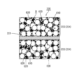
<Positive electrode mixture layer 223>
FIG. 5 is a sectional view of the positive electrode sheet 220 of the lithium-
ion
secondary battery 100. In the present embodiment, with the positive electrode
sheet 220,
both surfaces of the positive electrode current collector 221 are respectively
coated by the
positive electrode mixture 224 as shown in FIG. 5. This layer of the positive
electrode
mixture 224 (the positive electrode mixture layer 223) contains a positive
electrode active
material 610, an electrically conductive material 620, and a binder 630.
Moreover, in FIG.
5, the positive electrode active material 610, the electrically conductive
material 620, and the
binder 630 in the positive electrode mixture layer 223 are schematically
depicted enlarged so
as to clarify the structure of the positive electrode mixture layer 223.
[0054]
<Positive electrode active material 610>
In this case, the positive electrode active material 610 is constituted by
secondary
particles formed by the aggregation of a plurality of primary particles (not
shown) of a
lithium transition metal oxide. The secondary particles have a particle
diameter ranging
from approximately 3 vim to 10 m and more favorably from approximately 3 pim
to 8 m.
Here, a median diameter (d50) obtained from a particle size distribution
measured by a laser
diffractive scattering particle size distribution analyzer is adopted as the
particle diameter.
For example, LA-920 manufactured by HORIBA, Ltd. can be used as the laser
diffractive
21
CA 02817483 2013-05-09
scattering particle size distribution analyzer. Hereinafter, unless
specifically mentioned
otherwise, the term "positive electrode active material 610" shall signify
secondary particles.
In addition, particles that enable aggregation of a plurality of primary
particles (not shown) to
form secondary particles are favorably used as the positive electrode active
material 610. A
preferable example of the positive electrode active material 610 favorably
contains a
lithium-nickel-cobalt-manganese-based complex oxide attributable to a layered
structure as a
main component. This lithium-nickel-cobalt-manganese-based complex oxide has a
hexagonal crystalline system belonging to a-NaFe02 and adopts a layered R3m
structure.
[0055]
<Electrically conductive material 620>
In addition, for the electrically conductive material 620, carbon powders such
as
acetylene black, oil furnace black, graphitized carbon black, carbon black,
graphite, Ketjen
black, and graphite powder can be used. In this case, one type of a carbon
powder or a
plurality of types of carbon powder may be mixed at a predetermined ratio for
the electrically
conductive material 620. Here, the electrically conductive material 620 has a
smaller
particle diameter than the positive electrode active material 610. For
example, the particle
diameter of the primary particles of the electrically conductive material 620
ranges from
approximately 5 nm to 100 nm and more favorably from approximately 10 nm to 60
nm.
Furthermore, a primary structural diameter (which may also be referred to as
an aggregate
diameter) ranges from approximately 100 nm to 1000 nm and more favorably from
approximately 200 nm to 800 nm. A primary structural diameter can be measured
using a
dynamic scattering particle distribution analyzer. For example, Nanotrac UPA-
EX150
manufactured by NIKKISO CO., LTD. can be used as the dynamic scattering
particle
distribution analyzer.
[0056]
22
CA 02817483 2013-05-09
<Holes B of positive electrode mixture layer 223>
In the positive electrode mixture layer 223, as shown in FIG. 5, respective
particles
are bonded to each other due to the effect of the binder 630. As described
above, the
positive electrode mixture layer 223 is created by coating a positive
electrode mixture onto a
current collector (metal film), which is then subjected to drying and rolling.
Since the
positive electrode mixture layer 223 is in a state where the positive
electrode active material
610 and the electrically conductive material 620 are bonded by the binder 630,
a large
number of minute cavities exist between the respective particles. In addition,
the
electrically conductive material 620 is smaller than the positive electrode
active material 610
(secondary particles) and penetrate into a plurality of gaps of the positive
electrode active
material 610. The positive electrode active material 610 and the positive
electrode current
collector 221 are electrically connected to each other by the electrically
conductive material
620. In addition, the positive electrode mixture layer 223 has minute gaps
which may be
described as cavities. An electrolyte solution (not shown) penetrates into the
minute gaps of
the positive electrode mixture layer 223. Here, the gaps (cavities) formed
inside the positive
electrode mixture layer 233 will be referred to as "holes" when appropriate.
For example,
holes B of the positive electrode mixture layer 223 include holes between
particles of the
positive electrode active material 610, holes between particles of the
electrically conductive
material 620, and holes between particles of the positive electrode active
material 610 and
particles of the electrically conductive material 620. Furthermore, in some
cases, holes also
include those formed inside the positive electrode active material 610.
[0057]
<Operation during charging>
FIG. 14 schematically shows a state of the lithium-ion secondary battery 100
during
charging. During charging, as shown in FIG. 14, the electrode terminals 420
and 440 (refer
23
CA 02817483 2013-05-09
to FIG. 1) of the lithium-ion secondary battery 100 are connected to a charger
40. Due to
the effect of the charger 40, during charging of the secondary battery,
lithium ions (Li) are
released from the positive electrode active material 610 (refer to FIG. 5) in
the positive
electrode mixture layer 223 into the electrolyte solution 280 and, at the same
time, electrons
are emitted by the positive electrode. Meanwhile, at the negative electrode,
electrons are
stored and the lithium ions (Li) in the electrolyte solution 280 are adsorbed
by the negative
electrode mixture layer 243. Furthermore, during charging, electrons emitted
from the
positive electrode active material 610 (refer to FIG. 5) are sent to the
positive electrode
current collector 221 via the electrically conductive material 620 and are
further sent to the
negative electrode sheet 240 (refer to FIG. 1) via the charger 40 (refer to
FIG. 14).
[0058]
<Operation during discharging>
FIG. 15 schematically shows a state of the lithium-ion secondary battery 100
during
discharging. During discharging, as shown in FIG. 15, electrons are sent from
the negative
electrode to the positive electrode and lithium ions (Li) are released from
the negative
electrode mixture layer 243 into the electrolyte solution 280. In addition, at
the positive
electrode, the lithium ions (Li) in the electrolyte solution 280 are absorbed
by the positive
electrode active material 610 in the positive electrode mixture layer 223.
[0059]
In this manner, during charging and discharging of the secondary battery 100,
lithium ions (Li) migrate between the positive electrode mixture layer 223 and
the negative
electrode mixture layer 243 via the electrolyte solution 280. Therefore, the
positive
electrode mixture layer 223 desirably has necessary holes that allow the
electrolyte solution
280 to penetrate around the positive electrode active material 610 (refer to
FIG. 5). In other
words, necessary holes are desirably present around the positive electrode
active material 610
24
CA 02817483 2013-05-09
(refer to FIG 5) in the positive electrode mixture layer 223 so that lithium
ions can diffuse
around the positive electrode active material 610 (refer to FIG. 5) in the
positive electrode
mixture layer 223. Due to this configuration, since a sufficient amount of the
electrolyte
solution can exist around the positive electrode active material 610, lithium
ions (Li) can
migrate smoothly between the electrolyte solution 280 and the positive
electrode active
material 610.
[0060]
In addition, during charging, electrons are sent from the positive electrode
active
material 610 to the positive electrode current collector 221 via the
electrically conductive
material 620. In contrast, during discharging, electrons are returned from the
positive
electrode current collector 221 to the positive electrode active material 610
via the
electrically conductive material 620. In this manner, the transfer of
electrons between the
positive electrode active material 610 and the positive electrode current
collector 221
primarily takes place via the electrically conductive material 620.
[0061]
As shown, during charging, the smoother the migration of the lithium ions (Li)
and
the transfer of electrons, the higher the efficiency and the speed of charging
that can be
performed. In addition, during discharging, the smoother the migration of the
lithium ions
(Li) and the transfer of electrons, the lower the resistance of the battery
and the greater the
discharge capacity, which results in improved battery output.
[0062]
<Favorable mode of positive electrode mixture layer 223>
As described above, in order to improve output of a secondary battery, a
structure is
favorable which enables the migration of lithium ions (Li) and the transfer of
electrons to be
performed smoothly. The present inventors consider that in a preferred mode
for improving
CA 02817483 2013-05-09
output, the positive electrode mixture layer 223 favorably has necessary holes
around the
positive electrode active material 610 into which the electrolyte solution can
penetrate and, at
the same time, the electrically conductive material 620 is densely aggregated
between the
positive electrode active material 610 and the positive electrode current
collector 221. This
is because, in the positive electrode mixture layer 223, the presence of
necessary holes around
the positive electrode active material 610 into which the electrolyte solution
can penetrate
conceivably enables lithium ions to diffuse more smoothly at the positive
electrode. In
addition, dense aggregation of the electrically conductive material 620
between the positive
electrode active material 610 and the positive electrode current collector 221
conceivably
contributes toward the smooth transfer of electrons at the positive electrode.
[0063]
As described above, the present inventors consider that, favorably, the
positive
electrode mixture layer 223 has necessary holes outside and around the
positive electrode
active material 610 into which the electrolyte solution can penetrate and, at
the same time, the
electrically conductive material 620 is densely aggregated between the
positive electrode
active material 610 and the positive electrode current collector 221. Due to
this
configuration, the output of a secondary battery can be improved.
[0064]
<State of holes of positive electrode mixture layer 223>
A state of the holes of the positive electrode mixture layer 223 can be
examined by,
for example, the mercury intrusion method using a mercury porosimeter. In the
mercury
intrusion method, first, a sample of the positive electrode sheet 220 is
vacuumed and
immersed in mercury. In this state, as pressure applied to the mercury
increases, the
mercury gradually penetrates into smaller spaces. According to the mercury
intrusion
method, a volume Vb of holes formed inside the positive electrode mixture
layer 223 can be
26
CA 02817483 2015-05-21
obtained based on a relationship between an amount of mercury having
penetrated into the
positive electrode mixture layer 223 and the pressure applied to the mercury.
[0065]
Here, for example, AutoPoree III 9410 manufactured by Shimadzu Corporation can
be used as the mercury porosimeter. In this case, performing measurement by
setting the
pressure applied by the measuring instrument on the mercury to within a range
of 4 psi to
60,000 psi, a distribution of micropores within a range of approximately 50
i..tm to 0.003 ;Am
in the positive electrode mixture layer 223 can be measured. Furthermore, when
measuring
the positive electrode mixture layer 223, for example, the volume of holes
contained in the
positive electrode mixture layer 223 may be measured using a mercury
porosimeter on a
plurality of samples cut out from the positive electrode sheet 220 (refer to
FIG 2).
[0066]
<Porosity (VbNa)>
A ratio of holes in the positive electrode mixture layer 223 (porosity) can be
expressed as, for example, a ratio (VbNa) of a volume Vb of holes formed
inside the positive
electrode mixture layer 223 to an apparent volume Va of the positive electrode
mixture layer
223. Here, this ratio (VbNa) will be referred to as "porosity" when
appropriate. In
addition, whether or not the electrically conductive material 620 is densely
aggregated
between the positive electrode active material 610 and the positive electrode
current collector
221 can be detected based on, for example, sizes of the holes formed between
particles of the
electrically conductive material 620. The porosity (VbNa) can be obtained as a
ratio
(VbNa) of the volume Vb of holes as obtained by the mercury intrusion method
and the
apparent volume Va of the positive electrode mixture layer 223. In this case,
the apparent
volume Va of the positive electrode mixture layer 223 can be obtained as a
product of a
surface area of the positive electrode sheet and a thickness of the positive
electrode mixture
27
CA 02817483 2015-05-21
layer 223. Furthermore, the porosity (VbNa) can be approximated by other
methods.
Another method of measuring the porosity (VbNa) will be described below.
[0067]
<Another measurement method of porosity (VbNa)>
For example, the porosity (VbNa) can be approximated in a sectional sample of
the
positive electrode mixture layer 223 such as that shown in FIG 5 as a ratio
(Sb/Sa) of a
surface area Sb occupied by holes B included in a unit sectional area of the
positive electrode
mixture layer 223 and an apparent sectional area Sa of the positive electrode
mixture layer
223. In this case, the ratio (Sb/Sa) may be obtained from a plurality of
sectional samples of
the positive electrode mixture layer 223. The greater the number of sectional
samples of the
positive electrode mixture layer 223, the more accurate the approximation of
the porosity
(VbNa) by the ratio (Sb/Sa). In this case, for example, sectional samples may
be taken
along one arbitrary direction of the positive electrode sheet 220 from a
plurality of sections
perpendicular to the one direction.
[0068]
For example, the sectional samples of the positive electrode mixture layer 223
may
be obtained as sectional SEM images. A sectional SEM image is a sectional
photograph
taken by an electron microscope. For example, an arbitrary section of the
positive electrode
sheet 220 may be obtained by a CP process (Cross Section Polisher process).
For example,
a scanning electron microscope (FE-SEM) HITACHI S-4500 manufactured by
Hitachi
High-Technologies Corporation can be used as the electron microscope.
According to
sectional SEM images of the positive electrode mixture layer 223, based on
differences in
tonality and grayscale, a section A of a component material of the positive
electrode mixture
layer 223 and holes B formed inside the positive electrode mixture layer 223
can be
identified. Porosity measurement methods are not limited to the example
described above.
28
CA 02817483 2013-05-09
[0069]
<Micropore distribution>
The mercury intrusion method may also provide a micropore distribution of the
positive electrode mixture layer 223. FIG. 6 shows an example of a typical
micropore
distribution formed inside the positive electrode mixture layer 223. In this
case, micropore
distribution is expressed as micropore diameter¨differential micropore volume.
As shown
in FIG. 6, by expressing a typical micropore distribution of the positive
electrode mixture
layer 223 as micropore diameter¨differential micropore volume, approximately
two peaks
(DI and D2) appear in the differential micropore volume. Here, among the two
peaks (D1
and D2), the peak with the smaller micropore diameter will be referred to as a
first peak and
the peak with the larger micropore diameter will be referred to as a second
peak.
[0070]
The present inventors performed a detailed study on the two peaks (D1 and D2).
As a result, the following findings were made: the first peak micropore
diameter DI is mainly
attributable to holes in the electrically conductive material 620, and the
micropore diameter
D2 of the second peak is mainly attributable to holes in the positive
electrode active material
610. Conceivably, the smaller the first peak micropore diameter DI, the
smaller the holes in
the electrically conductive material 620 and the denser the aggregation of the
electrically
conductive material 620.
[0071]
In consideration thereof, the present inventors created a plurality of
evaluation test
lithium-ion secondary battery samples with different positive electrode
mixture layers.
Subsequently, with a focus on the porosity (Vb/Va) and the first peak
micropore diameter D1
described above, various tests were conducted on each sample. The results of
the evaluation
test are shown in Table 1.
29
[Table 1]
First peak DBP absorption Mixture composition
20 C discharge cycling
Squeeze Porosity micropore Electrically Electrically 10-second
Active Active
resistance increase rate
rate X (Vb/Va) diameter conductive conductive
Binder output (25 C)
material material
(-15 C)
Sample
D1
material
material
mL/100
_ ___ Pm mL/100 g wt% wt% wt%
W
g
1 0.200 0.30 0.169 20.1 140 87 10 3
37.2 1.28
2 0.277 0.32 0.134 22.6 140 87 10 3
39.1 1.21
3 0.246 . 0.35 0.150 22.6 140 87 10 3
40.8 1.25 ,
4 0.174 0.41 0.185 22.6 140 87 10 3
41.7 1.21 0
_
0.235 0.35 0.163 24.4 140 87 10 3 40.7
1.20
_
0
6 0.161 0.41 0.180 24.4 140 87 10 3
41.6 1.22 I.)
_
co
7 0.265 0.41 0.139 24.4 196 87 10 3
42.2 1.18 H
_ .
--.1
8 0.191 0.46 0.174 24.4 196 87 10 3
43.4 1.16 a,
co
9 0.317 0.35 0.119 24.4 196 92.2 6 1.8
40.9 1.19 u.)
I.)
0.262 0.41 0.140 24.4 196 92.2 6 1.8 42.1
1.18 0
H
11 0.187 0.46 0.177 24.4 196 92.2 6 1.8
43.2 1.15 u.)
1
12 0.345 0.32 0.110 35.2 140 _ 87 10
3 40.3 1.21 0
in
1
13 0.316 0.35 0.120 35.2 140 87 10 3
41.1 1.18 0
q3.
14 0.251 0.41 0.145 35.2 140 87 10 3
42.1 1.17
0.176 0.46 0.183 35.2 140 _ 87 10 3
43.1 1.20
16 , 0.403 0.35 0.099 _ 41.1 140 _ 87 10
3 41.4 1.14
17 0.346 0.41 0.118 41.1 140 87 10 3
42.4 1.12
18_ 0.223 0.49 0.157 41.1 140 87 10 3
44.2 1.09
19 0.142 0.55 0.210 41.1 140 87 10 3
49.6 1.10
0.509 0.30 0.066 41.1 196 87 10 3 40.1
1.15
21_ 0.496 0.32 0.069 41.1 196 87 10 3
40.9 1.12
22 0.475 0.35 0.078 41.1 196 87 10 3
41.7 1.10
23 _ 0.424 0.41_ 0.087 41.1 196 87 10 3
43.5 1.08
24 0.316 0.49 0.119 41.1 196 87 10 3
45.3 1.06
, 0.244 0.55 0.136 41.1 196 87 10 3
50.2 1.06
To be continued.
CA 02817483 2013-05-09
c)
C Nvn 7t vn CN CA CV cn vn V5 C-
C. 0. CA 00 Cn CT CD CV Vn 00
------------------------------ cc; cc; cc; cc; c,-; 4 4 4 4 4
CPs C) kr? in 00 Cq m c,.1 00
eµi 4 6 o6 (NI 6 e5 cNi 6
ign 4 4 =.4= vn vn CA CA CA CA CA
rn on cn rn cn en on cn cn rn cn rn on rn rn cn
C) C) c.C) C) C) C) CD CD CD C5 CD CD C5 CD C5 CD
NNNNNNNNNNNNNNNNOO OO 00 00 00 00 00 00 00 00 00 00 00 00 00 00
en
) cs 6 cs 6 cs õ õ CD CD CD CD CD CD CD CD
------------------------ m cn CN CN CT VD .ct
el cl cv ey cl 4 4 o6 od cNi 4 cri -4 -2
7t kr) kr) vn ----------------- vn CA CA cn 'et 7h
VD 00 00 00 C- C- CD CD CD C-
= r=- CT CD idn cn cs1 7t kin VD CT V5 vn CD
Cl CD CD CI Cl CA CA CV CA CA CA cn
cS 6 6 6 6 cS 6 6 6 cS 6 cS 6 6 cS cS
el c) r- cl c) r- oo ,47) r- 4
VD cn ,t =ct kin VD CA cn cl N cn 4 4 kr) kr) VD
C.) C5 6 6 e5 6 6 6 6 6 6 6 6 6 6 6
CD CT C.- 00 CA m r- VD V5 cn CA CA
CA Vn CD 7t Cl cn VD 00 CA 00 CT C- 00 CT Vn
71- 4 rn oq oA oq C) C) C) CD CD CD
C5 C5 C5 C5 C5 6 cS 6 6 6 6 6 6 cS 6 C5
VD N 00 CT CD CA cn ,f Vn VD C- 00 CT C5
CA Cl Cl CA cn on on on on on rn cn on on 4 ,r
CA 02817483 2013-05-09
[0072]
<Evaluation test battery>
FIG. 7 schematically shows an evaluation test battery 800. As shown in FIG. 7,
the
created evaluation test battery 800 is a cylindrical lithium-ion secondary
battery commonly
referred to as a 18650 cell.
[0073]
For the evaluation test battery 800, as shown in FIG. 7, a positive electrode
sheet
810, a negative electrode sheet 820, and two separators 830 and 840 were
laminated, and the
laminated sheet was wound to fabricate a wound electrode body 850 in which the
separators
830 and 840 were interposed between the positive electrode sheet 810 and the
negative
electrode sheet 820.
[0074]
In this case, sectional structures of the positive electrode sheet 810 and the
negative
electrode sheet 820 of the evaluation test battery 800 were approximately
similar to the
sectional structures of the positive electrode sheet 220 or the negative
electrode sheet 240 of
the lithium-ion secondary battery 100 (refer to FIG. 1) described earlier. In
addition, a
porous polyethylene sheet with a thickness of 20 lArn was used as the
separators 830 and 840.
This wound electrode body 850 was housed in an outer case 860 together with a
non-aqueous
electrolyte solution (not shown) to construct the evaluation test battery 800
(an evaluation test
18650 lithium-ion battery).
[0075]
Furthermore, for the evaluation test, active material particles having a
composition
represented by Lii 15Nio34Co033Mno3302 was used as the positive electrode
active material
610. However, the formation process of the active material particles can be
elaborated in
order to produce secondary particles of the active material particles that are
porous or have a
32
CA 02817483 2013-05-09
hollow form, a near-spherical shape, or shapes that differ from each other.
Due to such a
difference in structures or due to a difference in average particle diameters
in case of a same
structure, a difference arises in DBP absorption of the positive electrode
active material 610.
Here, the average particle diameter (d50) of the secondary particles of the
active material
particles was set to 3 IAM to 12 ktm. In addition, for the evaluation test,
acetylene black
(AB) was used as the electrically conductive material 620. Furthermore, for
the evaluation
test, N-methyl-2-pyrrolidone (NMP) was used as a solvent. Moreover,
polyvinylidene
fluoride (PVDF) was used as the binder 630.
[0076]
In addition, as shown in FIG. 7, the outer case 860 had an approximately
cylindrical
shape, and electrode terminals 870 and 880 internally connected to the
positive electrode
sheet 810 and the negative electrode sheet 820 were provided at both side ends
of the
cylindrical shape. Moreover, as a non-aqueous electrolyte solution for the
evaluation test
battery 800, a non-aqueous electrolyte solution was used which had a
composition obtained
by dissolving LiPF6 in a mixed solvent containing EC, DMC and EMC at a volume
ratio of
3:3:4 to a concentration of 1 mol/L.
[0077]
As shown in Table 1, the positive electrode active material 610 and the
electrically
conductive material 620 respectively having different DBP absorptions were
prepared for the
evaluation test. In addition, for each sample, a weight ratio of the positive
electrode active
material 610, the electrically conductive material 620, and the binder 630
contained in the
positive electrode mixture 224 was varied. Furthermore, for each sample, the
porosity
(Vb/Va) and the first peak micropore diameter D1 were varied.
[0078]
<DBP absorption>
33
CA 02817483 2013-05-09
DBP absorption is obtained in compliance with JIS K6217-4 "Carbon black for
rubber industry¨Fundamental characteristics¨Part 4: Determination of DBP
absorption".
Here, DBP (dibutylphthalate) is used as a reagent solution to be titrated
using a constant-rate
burette onto a test object powder (a powder of secondary particles 910 of the
positive
electrode active material 610), whereby a variation in viscosity
characteristics is measured by
a torque detector. Subsequently, an additive amount of the reagent solution
per unit weight
of the test object powder corresponding to a torque equivalent to 70% of a
maximum
generated torque is adopted as the DBP absorption (mL/ 100 g). For example, an
absorption
tester S410 manufactured by Asahisouken Co., Ltd. may be used as the DBP
absorption
measuring instrument.
[0079]
The measurement of the DBP absorption (mL/ 100 g) of the positive electrode
active
material 610 was performed by setting 60 g of the positive electrode active
material 610 to
the measuring instrument. In addition, the measurement of the DBP absorption
(mL/ 100 g)
of the electrically conductive material 620 was performed by setting 15 g of
the electrically
conductive material 620 to the measuring instrument.
[0080]
Moreover, the DBP absorption of the positive electrode active material 610 can
also
be measured after assembly of the battery. As a method of measuring the DBP
absorption of
the positive electrode active material 610 after assembly of the battery, for
example, the
battery is dismantled and the positive electrode sheet 220 (refer to FIG. 2)
is removed from
the battery. Next, the positive electrode mixture layer 223 is peeled off from
the positive
electrode current collector 221 of the positive electrode sheet 220. In this
case, the positive
electrode mixture layer 223 may be scraped off of the positive electrode
current collector 221.
Next, the positive electrode active material 610, the electrically conductive
material 620, and
34
CA 02817483 2013-05-09
the binder 630 are separated from each other. For example, debris of the
positive electrode
mixture layer 223 scraped off of the positive electrode current collector 221
may be
incinerated to burn away the electrically conductive material 620 and the
binder 630 which
are mainly composed of carbon components. Accordingly, the positive electrode
active
material 610 remains. The DBP absorption may be measured based on this
positive
electrode active material 610.
[0081]
In this case, as a method of scraping off the positive electrode mixture layer
223
from the positive electrode current collector 221 of the positive electrode
sheet 220, for
example, the positive electrode sheet 220 may be immersed in an NMP solution
(N-methyl-2-pyrrolidone) and then subjected to ultrasonic vibration to scrape
the positive
electrode mixture layer 223 off of the positive electrode current collector
221. In this case,
the NMP solution containing the positive electrode mixture layer 223 scraped
off of the
positive electrode current collector 221 may be filtered to extract the
positive electrode active
material 610. Furthermore, this positive electrode active material 610 may be
dried.
Moreover, when drying the filtered positive electrode active material 610, the
positive
electrode active material 610 may be incinerated to burn away the electrically
conductive
material 620 and the binder 630 which are contained as impurities.
[0082]
Furthermore, dismantling the battery is favorably performed in a state where
lithium
ions have returned to the positive electrode active material 610. For example,
the battery
may be dismantled after the battery has been sufficiently discharged.
[0083]
<Porosity (VbNa), first peak micropore diameter Dl>
As described earlier, the porosity (VbNa) and the first peak micropore
diameter D1
CA 02817483 2013-05-09
of the positive electrode mixture layer 223 can be measured based on the
volume Vb of holes
and the micropore distribution of the positive electrode sheet 810 of each
sample. The
volume Vb of holes and the micropore distribution may be measured by the
mercury
intrusion method.
[0084]
<Squeeze rate X>
In addition, the "squeeze rate X" in Table 1 represents a "squeeze rate X"
during the
production process of the positive electrode sheet 810 for each sample of the
evaluation test
battery 800. In this case, as shown in FIG. 8, the "squeeze rate X" is a value
obtained by
dividing a variation AT by which the thickness of the positive electrode
mixture layer 223
had varied in the rolling step when forming the positive electrode sheet 810
by a thickness TO
of the positive electrode mixture layer 223a prior to the rolling step
(squeeze rate X =
AT/T0). The variation AT by which the thickness of the positive electrode
mixture layer
223a had varied is expressed as a difference between the thickness TO of a
positive electrode
mixture layer 223a prior to the rolling step and a thickness Ti of a positive
electrode mixture
layer 223b after the rolling step (AT = TO - T1). Moreover, the thickness TO
of the positive
electrode mixture layer 223a prior to the rolling step and the thickness Ti of
the positive
electrode mixture layer 223b after the rolling step do not include the
thickness of the positive
electrode current collector 221. When the thickness of the positive electrode
current
collector 221 varies in the rolling step, the thickness of the positive
electrode current collector
221 may be excluded. In addition, for example, an average value of the
thickness T1 of the
positive electrode mixture layer 223b over a predetermined width (for example,
1000 mm) of
the positive electrode sheet 220 may be adopted as the thickness TO of the
positive electrode
mixture layer 223a prior to the rolling step and the thickness T1 of the
positive electrode
mixture layer 223b after the rolling step.
36
CA 02817483 2013-05-09
[0085]
Furthermore, for each sample, a plurality of evaluation test batteries 800
were
prepared. Same production conditions were applied for the evaluation test
batteries 800 for
a same sample including production conditions of the positive electrode sheet
810. In
addition, conditions other than those listed in Table 1 were set approximately
the same among
different samples. For example, an aluminum foil with a thickness of 15 1..tm
was used as
the positive electrode current collector. Furthermore, the amount of coating
by the positive
electrode mixture on the positive electrode current collector 221 was set to
approximately 15
mg/cm2.
[0086]
<Conditioning>
Next, a conditioning process, a measurement of rated capacity, and SOC
adjustment
for the evaluation test batteries constructed as described above will be
described in order.
In this case, the conditioning process is performed according to procedures 1
and 2
below.
Procedure 1: After reaching 4.1 V by charging at a constant current of 1 C,
pause for 5
minutes.
Procedure 2: After Procedure 1, charge at a constant voltage for 1.5 hours and
subsequently
pause for 5 minutes.
[0087]
<Measurement of rated capacity>
Next, rated capacity of the evaluation test batteries is measured according to
procedures 1 to 3 below after the conditioning process described above at a
temperature of
25 C and within a voltage range of 3.0 V to 4.1 V.
Procedure 1: After reaching 3.0 V by discharging at a constant current of 1 C,
discharge at a
37
CA 02817483 2013-05-09
constant voltage for 2 hours and subsequently pause for 10 seconds.
Procedure 2: After reaching 4.1 V by charging at a constant current of 1 C,
charge at a
constant voltage for 2.5 hours and subsequently pause for 10 seconds.
Procedure 3: After reaching 3.0 V by discharging at a constant current of 0.5
C, discharge at a
constant voltage for 2 hours and subsequently pause for 10 seconds.
Rated capacity: A discharge capacity (CCCV discharge capacity) of discharging
from the
constant current discharge to the constant voltage discharge in Procedure 3 is
adopted as the
rated capacity.
[0088]
<SOC adjustment>
SOC adjustment is performed on the evaluation test batteries prepared as
described
above according to procedures 1 and 2 below under a temperature environment of
25 C. In
this case, for example, SOC adjustment may be performed after the conditioning
process and
the rated capacity measurement described above.
Procedure 1: Charge at a constant current of 1 C from 3V to reach a charged
state equivalent
to approximately 60% of the rated capacity (SOC 60%). Here, "SOC" refers to
State of
Charge.
Procedure 2: After Procedure 1, charge at a constant voltage for 2.5 hours.
Accordingly, the evaluation test batteries 800 can be adjusted to a
predetermined
charged state.
[0089]
Next, the "10-second output (25 C)" and the "20 C discharge cycling resistance
increase rate (-15 C) in Table 1 will be described.
[0090]
<10-second output (25 C)>
38
CA 02817483 2013-05-09
A 10-second output (25 C) is obtained by the following procedures. Moreover,
in
the present embodiment, the measurement temperature embodiment was set to
normal
temperature (in this case, 25 C).
Procedure 1: As SOC adjustment, charge at a constant current of 1 C until SOC
60% is
reached, charge at a constant voltage at the SOC 60% for 2.5 hours, and
subsequently pause
for 10 seconds.
Procedure 2: After Procedure 1, discharge at a constant wattage (W) (constant
output) from
SOC 60%. Constant wattage discharge is performed by increasing current as
voltage
decreases due to the discharge so that a same amount of power is discharged
per unit time.
Then, measure the number of seconds until discharged voltage reaches a
predetermined cutoff
voltage from the state of SOC 60%.
Procedure 3: Repeat Procedures 1 and 2 by varying constant wattage discharge
conditions
within a range of 5 W to 50 W in Procedure 2 (refer to FIG. 16). Subsequently,
plot
respectively measured numbers of seconds until the predetermined cutoff
voltage on the
abscissa and plot power (W) conditions of constant wattage discharge during
the
measurements on the ordinate. Finally, calculate W at 10 seconds from an
approximate
curve.
According to the "10-second output (25 C)", high-rate output characteristics
can be
identified. In Table 1, among samples 1 to 41, the higher the numerical value,
the higher the
output characteristics of the battery.
[0091]
With respect to the 10-second output (25 C), FIG 16 shows a relationship
between
voltage drop and time of the constant wattage discharge obtained by Procedure
2.
In this case, for example, as shown in FIG. 16, constant wattage discharge is
performed at a predetermined power set within a range of 5 W to 50 W from the
state of SOC
39
CA 02817483 2013-05-09
60%. With respect to the power of the constant wattage discharge, FIG. 16
shows typical
examples of relationships between voltage drop and time (sec) for respective
constant
wattage discharges at 10 W, 25 W, 35 W, and 50 W. In this case, 2.5 V is set
as the
predetermined cutoff voltage. Here, as shown in FIG. 16, based on the
relationships
between voltage drop and time (sec) for respective constant wattage discharges
at 10 W, 25
W, 35 W, and 50 W, discharge output (W) of the constant wattage discharge
(amount of
discharge power of the constant wattage discharge) and the time (sec) until a
voltage drop
occurs is measured.
[0092]
In addition, FIG. 17 shows the approximate curve of Procedure 3 and a method
of
calculating the 10-second output. In this case, the approximate curve shown in
FIG 17 is
prepared as a graph in which time (sec) is set to the abscissa and output (W)
is set to the
ordinate. In addition, the discharge output (W) of constant wattage discharge
and the time
(sec) until a voltage drop occurs as obtained from FIG. 16 are plotted onto
the graph. An
approximate curve is drawn on the plots. Then, based on the approximate curve,
discharge
output at a position corresponding to 10 seconds on the abscissa of the graph
shown in FIG.
17 is obtained as a 10-second output.
[0093]
<20 C discharge cycle resistance increase rate (-15 C)>
For the "20 C discharge cycle resistance increase rate (-15 C)", after an
adjustment
is made to a charged state of SOC 60% in a temperature environment of -15 C by
the SOC
adjustment described above, charge-discharge cycles in which (I) to (V) below
constitute one
cycle is repeated 2500 times. The "20 C discharge cycle resistance increase
rate (-15 C)" in
Table 1 represents a rate of increase of resistance of the discharge of (I) in
the 2500th cycle.
Here, FIG 9 shows a charge-discharge cycle in this characteristic evaluation
test. Moreover,
CA 02817483 2013-05-09
this evaluation test is performed using a different evaluation test battery
800 to that used in
the "10-second output (25 C)" evaluation test.
[0094]
Hereinafter, one charge-discharge cycle constituted by (I) to (V) will be
described.
(I) Discharge for 10 seconds at a constant current of 20 C (here, 4.4 A).
(II) Pause for 5 seconds.
(III) Charge for 200 seconds at a constant current of 1 C.
(IV) Pause for 145 seconds.
(V) Measure the rate of increase of resistance during the discharging of (I)
for each
cycle.
However, the SOC adjustment described above is performed once every 100
repetitions of the charge-discharge cycle constituted by (I) to (V).
[0095]
<Samples 1 to 41>
Table 1 shows, for samples 1 to 41, a "squeeze rate X", a "porosity (Vb/Va)",
a "first
peak micropore diameter Dl", "DBP absorption (mL/100 g) of positive electrode
active
material 610 and electrically conductive material 620", the "positive
electrode active material
610", the "electrically conductive material 620", the "binder 630", a "10-
second output
(25 C)", and a "20 C discharge cycle resistance increase rate (-15 C)".
[0096]
As described earlier, according to the reasoning by the present inventors, in
order to
improve output of a secondary battery, the positive electrode mixture layer
223 favorably has
necessary holes around the positive electrode active material 610 into which
an electrolyte
solution can penetrate. When this concept is considered in terms of the
porosity (VbNa)
described earlier, it is conceivable that the positive electrode mixture layer
223 desirably has
41
CA 02817483 2013-05-09
a relatively large porosity (Vb/Va) described earlier. Furthermore, according
to the
reasoning by the present inventors, in order to improve output of a secondary
battery, the
electrically conductive material 620 is favorably densely aggregated between
the positive
electrode active material 610 and the positive electrode current collector 221
in the positive
electrode mixture layer 223. When this concept is considered in terms of the
first peak
micropore diameter D1 described earlier, the first peak micropore diameter D1
is desirably
relatively small.
[0097]
With samples having a same DBP absorption (mL/100 g) of the positive electrode
active material 610 and the electrically conductive material 620 and a same
mixture
composition (the weight ratio of the positive electrode active material 610,
the electrically
conductive material 620, and the binder 630), there is a tendency that the
greater the porosity
(Vb/Va), the higher the value of the "10-second output (25 C)" and the lower
the value of the
"20 C discharge cycle resistance increase rate (-15 C)". In other words,
conceivably, the
greater the porosity (Vb/Va) of the positive electrode mixture layer 223, the
greater the
improvement in characteristics of the secondary battery. Furthermore, even
with the same
porosity, the smaller the first peak micropore diameter DI, the higher the
value of the
"10-second output (25 C)" and the lower the value of the "20 C discharge cycle
resistance
increase rate (-15 C)".
[0098]
For example, as shown in Table 1, samples 2 to 4, samples 5 to 8, samples 9 to
11,
samples 12 to 15, samples 16 to 26, and samples 27 to 31 respectively have the
same DBP
absorption (mL/100 g) of the positive electrode active material 610 and the
electrically
conductive material 620 and the same mixture composition (the weight ratio of
the positive
electrode active material 610, the electrically conductive material 620, and
the binder 630).
42
CA 02817483 2013-05-09
In this case, there is a tendency that the higher the porosity (Vb/Va), the
higher the value of
the "10-second output (25 C)" and the lower the value of the "20 C discharge
cycle resistance
increase rate (-15 C)". Furthermore, for example, as shown by samples 6 and 7,
even with
the same porosity, the smaller the first peak micropore diameter D1, the
higher the value of
the "10-second output (25 C)" and the lower the value of the "20 C discharge
cycle resistance
increase rate (-15 C)". As shown, there is a tendency that the smaller the
first peak
micropore diameter Dl, the higher the value of the "10-second output (25 C)"
and the lower
the value of the "20 C discharge cycle resistance increase rate (-15 C)".
[0099]
In addition, for example, the samples 37 to 41 in Table 1 have values of the
"10-second output (25 C)" and the "20 C discharge cycle resistance increase
rate (-15 C)"
that are inferior to those of the samples 1 to 31 even though the samples 37
to 41 have a
relatively high porosity (Vb/Va). With the samples 37 to 41 in Table 1, the
first peak
micropore diameter DI is relatively large at D1 0.25. Therefore, it is
conceivable that the
electrically conductive material 620 in the positive electrode mixture layer
223 are not too
densely aggregated. This is conceivably one of the reasons for the inferior
values of the
"10-second output (25 C)" and the "20 C discharge cycle resistance increase
rate (-15 C)".
[0100]
As described as above, once the porosity (Vb/Va) of the positive electrode
mixture
layer 223 becomes relatively high, the electrolyte solution is able to
penetrate sufficiently into
the positive electrode mixture layer 223. As a result, lithium ions (Li) can
migrate between
the positive electrode active material 610 and the electrolyte solution more
smoothly. In
addition, when the first peak micropore diameter D1 is small, the electrically
conductive
material 620 in the positive electrode mixture layer 223 is densely
aggregated. When the
electrically conductive material 620 is densely aggregated, electron transfer
occurs more
43
CA 02817483 2013-05-09
readily between the positive electrode active material 610 and the positive
electrode current
collector 221. As shown, the output of the secondary battery can conceivably
be improved
by having a relatively high porosity (Vb/Va) and a relatively small first peak
micropore
diameter Dl.
[0101]
In consideration of the above, according to findings made by the present
inventors,
for example, the porosity (Vb/Va) described above may satisfy approximately
0.30 (Vb/Va)
and the first peak micropore diameter D1 may satisfy D1 0.24 vim. Accordingly,
the
output of the secondary battery can be generally improved. In addition, due to
the
tendencies described above, the porosity (Vb/Va) may satisfy 0.30 < (Vb/Va)
and, more
favorably, the porosity (Vb/Va) may satisfy 0.38 (Vb/Va). Furthermore, the
first peak
micropore diameter D1 may satisfy D1 <0.24 iAm or even smaller so as to
satisfy D1 0.20
vim. Moreover, even more favorably, the micropore diameter D1 may satisfy D1
0.18 pm.
[0102]
According to this configuration, since the porosity (Vb/Va) of the positive
electrode
mixture layer 223 is relatively high, a necessary amount of the electrolyte
solution penetrates
into the positive electrode mixture layer 223 and lithium ions (Li) can
migrate more smoothly
between the positive electrode active material 610 and the electrolyte
solution. In addition,
since the first peak micropore diameter D1 is relatively small, in terms of
structure, the
electrically conductive material 620 is densely aggregated and electron
transfer occurs more
readily between the positive electrode active material 610 and the positive
electrode current
collector 221. Therefore, migration of lithium ions (Li) and transfer of
electrons at the
positive electrode occurs more readily and the output of the secondary battery
can be
improved.
[0103]
44
CA 02817483 2013-05-09
Furthermore, although an upper limit is not particularly set, the porosity
(Vb/Va)
may have an appropriate and feasible magnitude. Therefore, the porosity
(Vb/Va) may have
an appropriate and feasible magnitude and, for example, may be around 0.65.
Similarly, a
lower limit of the first peak micropore diameter D1 that is mainly
attributable to holes in the
electrically conductive material 620 is not particularly set. Therefore, the
first peak
micropore diameter D1 may have an appropriate and feasible size and, for
example, may be
around 0.05.
[0104]
Furthermore, in view of the samples 32 to 41, it is conceivable that DBP
absorption
(mL/100 g) may also influence the output characteristics of the secondary
battery.
Therefore, when considering the DBP absorption (mL/100 g) of the positive
electrode active
material 610, the DBP absorption B of the positive electrode active material
is more
favorably approximately 30 (mL/100 g) B. Even more favorably, the DBP
absorption B
of the positive electrode active material may be 33 (mL/100 g) BI. While an
upper limit
of the DBP absorption B of the positive electrode active material is not
particularly set, for
example, the DBP absorption B of the positive electrode active material may
also satisfy 60
(mL/100 g). In addition, when considering the DBP absorption (mL/100 g) of the
electrically conductive material 620, the DBP absorption D of the electrically
conductive
material 620 may satisfy approximately 100 (mL/100 g) D. While an upper limit
of the
DBP absorption D of the electrically conductive material 620 is not
particularly set, for
example, the DBP absorption D of the electrically conductive material 620 may
be 300
(mL/100 g).
[0105]
<Forming process of positive electrode mixture layer 223>
Furthermore, as described earlier, a process of forming the positive electrode
mixture
CA 02817483 2013-05-09
layer 223 comprises a coating step, a drying step, and a rolling step. In the
coating step, the
positive electrode mixture 224 containing the positive electrode active
material 610 and the
electrically conductive material 620 is coated onto the positive electrode
current collector
221. In the drying step, the positive electrode mixture 224 coated onto the
positive
electrode current collector 221 in the coating step is dried. In the rolling
step, the positive
electrode mixture layer 223 dried in the drying step is rolled. A method of
achieving the
porosity (Vb/Va) and the first peak micropore diameter D1 described above when
performing
these steps involves adjusting a rolling quantity (the squeeze rate X) in the
rolling step.
[0106]
In other words, according to findings made by the present inventors, the first
peak
micropore diameter D1 described above and the squeeze rate X in the rolling
step have a
generally correlative relationship as shown in FIG. 10. Therefore, the squeeze
rate X may
be determined to a certain degree when adjusting the rolling quantity of the
rolling step.
[0107]
In this case, for example, the rolling quantity of the rolling step may be
adjusted so
that the squeeze rate X is within a range of 0.09 X 0.60. The squeeze rate X
is a value
obtained by dividing a variation AT by which a thickness of the positive
electrode mixture
layer 223 varies due to the rolling step by a thickness TO of the positive
electrode mixture
layer 223 prior to the rolling step. Subsequently, after the rolling step, the
positive electrode
mixture layer 223 that satisfies required conditions 1 and 2 may be obtained,
where:
condition 1 requires that a ratio (Vb/Va) of a volume Vb of holes formed
inside the positive
electrode mixture layer 223 after the rolling step to an apparent volume Va of
the positive
electrode mixture layer 223 after the rolling step satisfies 0.30 (Vb/Va); and
condition 2
requires that, in a micropore distribution of differential micropore volume
with respect to
micropore diameter as measured by the mercury intrusion method, the positive
electrode
46
CA 02817483 2013-05-09
mixture layer 223 after rolling in the rolling step has a first peak at which
a micropore
diameter D1 satisfies DI 0.25 i_tm and a second peak at which a micropore
diameter D2 is
greater than the first peak micropore diameter Dl.
[0108]
As described above, the squeeze rate X may be adjusted in the rolling step so
that a
required porosity (Vb/Va) is obtained and, at the same time, the first peak
micropore diameter
DI has a required size. Moreover, conceivably, the greater the squeeze rate X,
the smaller
the first peak micropore diameter D1 and the denser the electrically
conductive material 620
in the positive electrode mixture layer 223. In this case for example, the
rolling quantity
may be adjusted so that the squeeze rate X satisfies 0.2 X.
[0109]
In addition, the lower the density of the positive electrode mixture layer 223
after the
rolling step, the better. Therefore, the density of the positive electrode
mixture layer 223 is
favorably set lower even before the rolling step. With the lithium-containing
complex oxide
described earlier, for example, the density of the positive electrode mixture
layer 223 prior to
the rolling step may be set to 1.8 g/mL or lower.
[0110]
<Example of preferable positive electrode active material 610>
Hereinafter, a preferable positive electrode active material 610 for achieving
the
positive electrode mixture layer 223 described above will be exemplified.
[0111]
As described earlier, there is a tendency that the higher the porosity (Vb/Va)
of the
positive electrode mixture layer 223, the greater the improvement in output
characteristics of
the secondary battery. However, with a positive electrode active material 610
consisting of
solid particles, there is a limit to increasing porosity (Vb/Va). In addition,
there is also a
47
CA 02817483 2013-05-09
limit to reducing the first peak micropore diameter Dl. Therefore, in order to
increase the
porosity (VbNa) and reduce the first peak micropore diameter D1 at the same
time, it is
important to select a positive electrode active material 610 suitable for this
purpose.
[0112]
For example, conceivably, a desirable mode improves porosity due to holes in
the
positive electrode active material 610 itself. In addition, reducing the first
peak micropore
diameter D1 may require significantly adjusting the rolling quantity in the
rolling step by, for
example, increasing the squeeze rate X. In doing so, even if there are holes
in the positive
electrode active material 610 itself, it is conceivably required that the
positive electrode
active material 610 has sufficient strength to withstand the load of the
rolling step.
[0113]
As the positive electrode active material 610, although not shown, the
particles of
the positive electrode active material 610 may be granulated by spray-drying
to obtain a
particulate structure having minute holes therein. The porosity (VbNa) can
also be
improved by using such a positive electrode active material 610.
[0114]
For example, as shown in FIG 11, a positive electrode active material 610a may
be
formed of secondary particles 910 resulting from the aggregation of a
plurality of primary
particles 900 of a lithium transition metal oxide. In this case, a hollow
portion 920 may be
formed in the secondary particles 910. According to this positive electrode
active material
610a, a hollow portion 920 is formed in the secondary particles 910.
Therefore, the porosity
(Vb/Va) of the positive electrode mixture layer 223 can be improved.
Furthermore, in this
mode, a large number of micropores too minute to be illustratable are
desirably formed
between the primary particles 900 in the secondary particles 910 to create a
configuration
which enables the electrolyte solution to penetrate into the hollow portion
920.
48
CA 02817483 2013-05-09
Accordingly, since the primary particles 900 can be utilized also inside the
hollow portion
920, the output characteristics of the secondary battery can be improved.
Hereinafter, a
structure of the positive electrode active material 610 having such a hollow
portion 920 will
be referred to as a "hollow structure" when appropriate.
[0115]
In addition, as another mode, for example, a positive electrode active
material 610
may further have through holes 930 that penetrate the secondary particles 910
so as to
connect the hollow portion 920 to the outside as shown in FIG. 12.
Hereinafter, a structure
of the positive electrode active material 610 having such through holes 930
will be referred to
as a "holed hollow structure" when appropriate.
[0116]
Due to the positive electrode active material 610b, an electrolyte solution is
able to
migrate more easily between the hollow portion 920 and the outside through the
through
holes 930 and the electrolyte solution in the hollow portion 920 is
appropriately replaced.
Therefore, a depletion or a shortage of the electrolyte solution is less
likely to occur inside the
hollow portion 920. As a result, the primary particles 900 of the positive
electrode active
material 610 are more actively utilized inside the hollow portion 920.
Accordingly, the
output characteristics of the secondary battery can be further improved.
[0117]
In this case, an opening width k of the through holes 930 may be on average
0.01 pm
or more. Accordingly, the electrolyte solution can penetrate into the hollow
portion 920
more reliably and the effects described above can be more readily obtained. In
addition, the
opening width k of the through holes 930 may be on average 2.0 pim or less.
Here, the
opening width k of the through holes 930 refers to the length across a portion
where the
through holes 930 are narrowest (an inner diameter of the through holes 930)
among a path
49
CA 02817483 2013-05-09
which penetrates through the secondary particles and which extend to the
hollow portion 920
from the outside of the active material particles. Moreover, when there are a
plurality of
through holes 930 in the hollow portion 920, an evaluation may be performed
with the
through hole 930 having the greatest opening width k among the plurality of
the through
holes 930. Furthermore, the opening width k of the through holes 930 may be on
average
2.0 ktrn or less, favorably on average 1.0 pm or less, and more favorably on
average 0.5 !Am
or less.
[0118]
In addition, the number of through holes 930 may be around on average 1 to 20
per
one particle of the positive electrode active material 610b and more favorably
around on
average Ito 5. According to the positive electrode active material 610b
structured in this
manner, favorable battery performance can be more stably demonstrated (such as
by
inhibiting deterioration caused by charge-discharge cycling). Moreover, the
number of
through holes 930 in the positive electrode active material 610b of the holed
hollow structure
may be obtained by, for example, ascertaining the number of through holes per
particle for at
least 10 or more arbitrarily selected active material particles and then
determining an
arithmetic average thereof. A method of producing the positive electrode
active material
610b with this holed hollow structure may include, for example, a raw material
hydroxide
formation step, a mixing step, and a calcining step.
[0119]
In this case, the raw material hydroxide formation step is a step of supplying
ammonium ions to an aqueous solution of a transition metal compound and
precipitating
particles of a transition metal hydroxide from the aqueous solution. The
aqueous solution
favorably contains at least one transition metal element that composes the
lithium transition
metal oxide. In addition, the raw material hydroxide formation step favorably
includes a
CA 02817483 2013-05-09
nucleation stage in which a transition metal hydroxide is precipitated from
the aqueous
solution at pH 12 or higher and at an ammonium ion concentration of 25 g/L or
less and a
particle growth stage in which the precipitated transition metal hydroxide is
grown at a pH of
less than 12 and at an ammonium ion concentration of 3 g/L or more.
[0120]
Furthermore, the mixing step is a step of mixing particles of the transition
metal
hydroxide obtained in the raw material hydroxide formation step with a lithium
compound to
prepare an unfired mixture. Moreover, the calcining step is a step of
calcining the mixture
obtained in the mixing step to obtain active material particles. According to
this production
method, the positive electrode active material 610b having a holed hollow
structure can be
suitably produced.
[0121]
In addition, in this case, the calcining step may be carried out such that a
maximum
calcining temperature is 800 C to 1100 C (favorably, 800 C to 1000 C). As a
result, since
the primary particles can be adequately sintered, active material particles
having a desired
average hardness can be preferably produced. This calcining step is favorably
carried out so
that, for example, secondary particles are formed in which gaps are
substantially not present
at the grain boundaries of the primary particles at portions other than the
hollow portion 920
and the through holes 930.
[0122]
Furthermore, the calcining step may include a first calcining stage in which
the
mixture is fired at a temperature Ti of 700 C to 900 C and a second calcining
stage in which
the result of the first calcining stage is fired at a temperature T2 of 800 C
to 1100 C
(favorably, 800 C to 1000 C) that is higher than the calcining temperature T1
of the first
calcining stage.
51
CA 02817483 2013-05-09
[0123]
In a favorable aspect of the active material particle production method
disclosed
herein, the calcining step includes a first calcining stage in which the
mixture is fired at a
temperature Ti of 700 C to 900 C and a second calcining stage in which the
result of the first
calcining stage is fired at a temperature T2 of 800 C to 1100 C (favorably,
800 C to 1000 C)
that is higher than the calcining temperature Ti of the first calcining stage.
As a result of
calcining the mixture in an aspect that includes these first and second
calcining stages,
favorable active material particles having a holed hollow structure disclosed
herein (refer to
the positive electrode active material 610b shown in FIG. 12) can be suitably
produced. In
addition, for example, by suitably elaborating the calcining step, the
positive electrode active
material 610a with a "hollow structure" such as that shown in FIG. 11 can be
obtained by a
similar method.
[0124]
Furthermore, in this case, BET specific surface areas of the positive
electrode active
materials 610a and 610b having a hollow structure favorably range from 0.5 to
1.9 m2/g.
The positive electrode active materials 610a and 610b having a hollow
structure and
satisfying the requirement regarding BET specific surface area described above
can be used
in a positive electrode of the lithium-ion secondary battery 100 and are able
to yield a battery
that stably demonstrates higher performance. For example, a lithium secondary
battery can
be constructed which has low internal resistance (or in other words, favorable
output
characteristics) and which demonstrates little increase in resistance
attributable to
charge-discharge cycling (particularly, charge-discharge cycling that includes
high-rate
discharge).
[0125]
If the BET specific surface area of the active material particles is
excessively small,
52
CA 02817483 2013-05-09
effects of improving battery performance (for example, the effect of reducing
internal
resistance) tend to decrease. On the other hand, if the BET specific surface
area is
excessively large, the effect of inhibiting deterioration attributable to
charge-discharge
cycling tends to decrease. According to the favorable positive electrode
active materials
610a and 610b having a hollow structure and satisfying the requirement
regarding the BET
specific surface area disclosed herein, an improvement of high-rate
characteristics (for
example, at least one of inhibition of increases in resistance caused by high-
rate cycling in the
manner of a high-rate cycling test to be subsequently described, and
improvement of
high-rate discharge performance), and prevention of wear deterioration (for
example, at least
one of inhibition of increases in resistance with respect to endurance cycling
in the manner of
an endurance test to be subsequently described, and improvement of capacity
retention rate)
can be realized simultaneously.
[0126]
In addition, for example, the positive electrode active material 610a with a
"hollow
structure" and the positive electrode active material 610b with a "holed
hollow structure" may
have an average hardness of 0.5 MPa or more as obtained by measuring dynamic
hardness
under conditions of a loading speed of 0.5 mN/sec to 3 mN/sec using a flat
diamond indenter
having a diameter of 50 i_tm.
[0127]
In another favorable aspect of the active material particles disclosed herein,
the
average hardness of the positive electrode active material 610a having a
hollow structure and
the positive electrode active material 610b having a holed hollow structure is
roughly 0.5
MPa or more. Here, average hardness refers to a value obtained by measuring
dynamic
microhardness under conditions of a loading speed of 0.5 mN/sec to 3 mN/sec
using a flat
diamond indenter having a diameter of 50 gm. For example, a microhardness
tester
53
CA 02817483 2013-05-09
MCT-W201 manufactured by Shimadzu Corporation can be used for the dynamic
microhardness measurement. In this manner, active material particles having a
hollow
structure and high average hardness (or in other words, high shape retention)
as shown in
FIGS. 11 and 12 are able to yield a battery that stably demonstrates higher
performance.
Therefore, for example, a contribution can be made to constructing a lithium
secondary
battery that has low internal resistance (or in other words, favorable output
characteristics)
and demonstrates little increase in internal resistance attributable to charge-
discharge cycling
(particularly, charge-discharge cycling that includes high-rate discharge).
[0128]
In addition, the positive electrode active material 610a having a hollow
structure and
the positive electrode active material 610b having a holed hollow structure
may be a lithium
transition metal oxide which has a layered structure and which contains nickel
as a
constituent element. Furthermore, the positive electrode active material 610a
having a
hollow structure and the positive electrode active material 610b having a
holed hollow
structure may be a lithium transition metal oxide which has a layered
structure and which
contains nickel, cobalt, and manganese as constituent elements.
[0129]
In addition, for example, the positive electrode active material 610a having a
hollow
structure and the positive electrode active material 610b having a holed
hollow structure
favorably have an average particle diameter within a range of approximately 3
1.i.m to 101.1.M.
Furthermore, an average opening size of the through holes 930 of the positive
electrode
active material 610b having a holed hollow structure is favorably 1/2 or less
with respect to
the average particle diameter of the positive electrode active material 610b.
Since the
average opening size lies within a suitable range, the positive electrode
active material 610b
is able to easily secure a desired average hardness while suitably
demonstrating effects of
54
CA 02817483 2013-05-09
improving battery performance (such as the effect of reducing internal
resistance) as a result
of having a holed hollow structure. Thus, favorable battery performance can be
demonstrated more stably.
[0130]
While an example of a suitable positive electrode active material has been
described
as a positive electrode active material contained in a positive electrode
mixture layer of a
secondary battery, the positive electrode active material of a secondary
battery according to
the present invention is not limited to the above unless specifically
mentioned otherwise.
[0131]
In addition, the present invention proposes a structure of a positive
electrode mixture
layer capable of improving output of a secondary battery comprising a positive
electrode in
which the positive electrode mixture layer is coated onto a current collector.
While a
lithium-ion secondary battery has been exemplified as the secondary battery,
the present
invention is not limited to a lithium-ion secondary battery unless
specifically mentioned
otherwise. Furthermore, the present invention can contribute to improving the
output of a
secondary battery. Therefore, the structure according to the present invention
is particularly
preferable for use in a secondary battery used as a vehicle drive power supply
such as a drive
battery of a hybrid vehicle or an electrical vehicle which is required to have
superior
high-rate output characteristics and high-rate cycling characteristics. In
this case, for
example, as shown in FIG. 13, the secondary battery can be preferably used as
a vehicle drive
battery 1000 for driving a motor of a vehicle 1 such as an automobile in the
form of an
assembled battery in which a plurality of the secondary batteries are
connected in series.
[0132]
Although a lithium-ion secondary battery according to an embodiment of the
present
invention has been exemplified and various embodiments of the present
invention with
=
CA 02817483 2013-05-09
respect to a mixture layer of the lithium-ion secondary battery have been
described, the
present invention is not limited to any of the embodiments above. Moreover,
while a
lithium-ion secondary battery is exemplified above, the present invention may
be applied to
structures of positive electrode mixture layers in secondary batteries other
than a lithium-ion
secondary battery.
Reference Sings List
[0133]
100 lithium-ion secondary battery
200 wound electrode body
220 positive electrode sheet
221 positive electrode current collector
222 uncoated portion
222a intermediate portion
223 positive electrode mixture layer
223a positive electrode mixture layer
223b positive electrode mixture layer
224 positive electrode mixture
240 negative electrode sheet
241 negative electrode current collector
242 uncoated portion
243 negative electrode mixture layer
244 negative electrode mixture
245 heat-resistant layer
262 separator
264 separator
56
CA 02817483 2013-05-09
300 battery case
310 gap
320 container main body
322 joint of lid and container main body
340 lid
360 safety valve
420 electrode terminal (positive electrode)
440 electrode terminal (negative electrode)
610 positive electrode active material
610a positive electrode active material ("hollow structure")
610b positive electrode active material ("holed hollow structure")
620 electrically conductive material
630 binder
800 evaluation test battery
810 positive electrode sheet
820 negative electrode sheet
830, 840 separator
850 wound electrode body
860 outer case
870 electrode terminal
900 primary particles
910 secondary particles
920 hollow portion
930 through holes
1000 vehicle drive battery
57