Note: Descriptions are shown in the official language in which they were submitted.
CA 02817940 2013-06-10
SORTATION CONVEYOR
[00011
Background of the Invention
[00021 This invention relates to a sortation conveyor with pusher shoes
which
travel laterally (transverse to the longitudinal direction of travel of the
sortation conveyor) to divert articles carried by the upper conveying
surface of the sortation conveyor to diverts, and more particularly to a
sortation conveyor in which the pushers are guided along divert guide
paths so as to gently engage and gradually accelerate conveyed ,
articles, such as cartons, laterally onto the diverts. The invention will
be disclosed in connection with, but not limited to, a sortation system
which includes a divert guide path guide track, with an arcuate section,
configured to produce gentle initial contact between the pushers and
conveyed articles followed by adual acceleration.
CA 02817940 2013-06-10
.7)
[00031 It is believed that a sortation conveyor constructed in accordance
with
the teachings of the present invention may effectively be operated at
high speeds, such as 650 feet per minute and higher, including for
example, 700 feet per minute, 800 feet per minute, 1000 feet per
minute and possibly even higher, having a variable throughput rate
based on carton length and gaps, while maintaining control of the
conveyed articles without cartons rotating substantially beyond the
final divert angle, toppling or otherwise upsetting the articles.
Sortation conveyors constructed in accordance with the teachings of
the present invention may also be operated at lower speeds with
improved control. Such improved control results in a higher
percentage of articles being successfully diverted when utilizing the
teachings of the present invention in comparison to when utilizing the
teachings of the prior art.
Brief Description of the Drawings
[00041 The accompanying drawings incorporated in and forming a part of the
specification illustrate several aspects of the present invention, and
together with the description serve to explain the principles of the
invention. In the drawings:
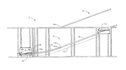
f00051 Fig. I is a plan view of a portion of a sortation conveyor
constructed
according to the present invention, with the conveying surface and
pushers omitted so as to show the divert guide track and switch
assembly.
[00061 Fie. 2 is a plan view of the portion of the sortation conveyor shown
in
Fig. I, except that a plurality of pushers are illustrated at various
locations along the divert guide track. The pushers illustrated are not
adjacent to each other.
[0007] Fig. 3 is an enlarged, fragmentary view of the portion of the
sortation
conveyor illustrated in Fig. 1 with non-adjacent pushers and cartons,
CA 02817940 2013-06-10
3
illustrating interaction between cartons and pushers at different stages
during divert.
10008] Fig. 4 illustrates the switch assembly and divert guide
track of a
sortation conveyor constructed in accordance with Fig. 1, and the
profile of the path followed by a pusher.
[0009] Fig. 5 is an enlarged, fragmentary view of the switch
assembly and the
leading end of the divert guide track of the sortation conveyor of Fig. .
[0010] Fig. 6 is an enlarged view of the divert switch
assembly showing the
=
pusher pin and bearing/cam traveling through the switch guide path,
[0011] Fig. 7 is an. enlarged, fragmentary view of a portion
of the switch
assembly and the leading end of divert guide tack shown in Fig. 5,
with two pushers shown.
100121 Figs. 8-12 are graphs depicting illustrative lateral
speed and lateral
acceleration profiles of the pushers, leading into, within, and out of the
arcuate section.
100131 Reference will now be made in detail to an embodiment
of the invention,
an example of which is illustrated in the accompanying drawings.
Detailed Description Of An Embodiment Of The Invention
100141 Referring now to the drawings in detail, which depict
an exemplary
embodiment of the present invention, wherein like numerals indicate the
same elements throughout the views, Fig. 1 is a plan view of a portion
of a saltation conveyor, generally indicated at 2, showing a divert
location constructed according to the present invention, with the
endleSs conveying surface and the pushers carried by the endless
conveying surface of the sortation conveyor omitted so as to show the
switch assembly 8, divert guide track 10 and return 12. Conveyor 2
CA 02817940 2013-06-10
4
includes divert location 3, with divert 4 aligned thereat to receive
articles which. are selectively diverted to divert 4 by sortation conveyor
2 at divert location 3. As used herein, divert location refers to a section
of a conveyor whereat an article is directed from the conveyor and
discharged transversely onto to a divert. Divert 4 may be any
receiving means, such as a powered or non-powered conveyor, a chute,
a hopper, a bag or a bin. Each divert 4 has at least one associated
transverse divert guide path 6, upstream of reentry block 12. Sortation
conveyor 2 includes one or more diverts and associated divert guide
paths.
100151 As shown, divert guide path 6 is at least partially defined by
divert
guide track 10, which in the embodiment depicted includes arcuate
section 14 and straight section 16. Divert guide track 10 is disposed ,
downstream of the associated corresponding switch assembly 8,
meaning that divert guide track 10 receives the guiding elements of the
pushers diverted at switch assembly 8 and are therefore guided by
divert guide track 10. The associated reentry 12 is downstream of
divert guide track 10 and switch assembly S. in the depicted
embodiment, divert guide path 6 includes straight section 18 with
arcuate section 14 disposed downstream thereof. The present
invention may be practiced without straight section IS upstream of
arcuate section 14.
[0016} In the depicted embodiment, arcuate section 14 forms 170 of a
circular
arc (from 30 to 20' relative to the longitudinal downstream direction of
travel) with a 15 foot radius for the 20' divert 4, although the present
invention is not limited to this dimension, nor to a constant radius arc,
nor to the total angle of the arc, nor to the starting or ending angles of
the arc. As is well known, the radius of a point on a non-constant
radius arc is also referred to as the radius of curvature. For example,
an arc with a 12 foot radius may be used with a 20' divert, or an arc
CA 02817940 2013-06-10
with an 8 or 10 foot radius may be used with a 30 divert. A larger
radius is generally better, but the larger the radius, the more space
required for the sortation system, An arcuate section 14 having a
radius ranging from 12 inches to 180 inches and up (space allowing)
can provide improved control during carton divert, including, but not
limited to, at speeds below the high speeds at which the present
invention may be advantageously used. Arcuate section 14 may be
alternatively configured to define a parabolic shape or a complex
CUTVe.
[00171 It is noted that, without departing from the teachings of this
invention;
the same result as a smooth arc may be obtained by a series of
relatively short straight sections disposed end to end, non-colinear to
each other, which it is noted is essentially the nature of any curved
surface at its basic level, and such configuration is considered to be
arcuate. Arcuate section 14 defines an arcuate divert guide path
portion which distributes the farce necessary to rotate and laterally
accelerate articles toward divert 4 over a longitudinal and lateral
distance instead of an abrupt initial force being applied to the article
being diverted as the result of the pusher elements moving transversely
at the final divert angle or a large divert angle when the article is
initially contacted. Thus, a reduced force is applied to rotate and
laterally accelerate each carton, applied over a longer time and
distance.
[0018j In the embodiment depicted, divert guide path 6 comprises a
plurality
of divert angles. The divert angle at any point along a pusher's path is
the angle of a line tangent to the pusher's path at that point measured
relative to the longitudinal downstream direction. Thus, for any point
along divert guide path 6, the divert angle is the angle of a line tangent
to the divert guide path at that point measured relative to the
longitudinal downstream direction. The final divert angle is the =ale
CA 02817940 2013-06-10
6
at which the pushers are traveling when articles are essentially
discharged from the sortation conveyor (prior to entering reentry 12).
A carton under control is discharged at the final divert angle. Usually
the angle of a divert adjacent the divert location is the same as the final
divert angle, but such is not a requirement of this invention. Divert 4
may be disposed at an angle different from the divert angle of section
16. Typical final divert angles include 200 and 30 , which are referred
to as 200 and 30 diverts, respectively. Divert guide track 10 includes
straight section 18, disposed at a constant divert angle of 3 . In the
depicted embodiment, the divert angle of section 18 matches the divert
angle of exit section 8g, which will be described below. As shown,
sections 14 and 18 are formed from a single piece, with the divert
angle of entrance 14a of section 14, in the depicted embodiment
preferably matching the divert angle of upstream straight section 18.
In the embodiment depicted, entrance 14a is disposed at a 3 divert
angle, matching the 3' divert angle of section 18. Exit end 14b of
section 14 preferably matches the divert angle of straight section 16,
and in the embodiment depicted is disposed at a 20 divert angle
matching the divert angle of straight section 16. Arcuate section 14
thus comprises a plurality of divert angles. Divert guide track 10, and
divert guide path 6, comprises a plurality of divert angles: that of
straight section 18, those of arcuate section 14 and that of straight
section 16.
[0019] Straight section
16 defines the final divert angle and may be disposed
at any suitable angle, such as 20 or 30 , as is well known, with exit
end 14b preferably matching the final divert angle. It is noted that
entrance 16a of section 16 is approximately aligned with the
intersection 4a of divert 4 with conveyor 2. Although not required, this
configuration is believed preferable as it allows the divert's throat
width to be maintained. It is preferred, but not required, that exit end
CA 02817940 2013-06-10
14b of arcuate section 14 not extend past a line, perpendicular to
section 16, passing through intersection 4a.
[00201 Fig. 2 is similar to Fig. 1, with a plurality of pushers 22a-f
illustrated at
various locations along the divert guide path. Pushers 22a-f are not
adjacent to each other and diverted pushers therebetween have been
omitted for clarity. Pusher 22a is illustrated traveling along the home
or charge path indicated generally by line 7. Unless diverted at switch
assembly 8, pusher 22a travels along the home path downstream of
switch assembly S. Pusher 22b has been diverted and is traveling
along straight section 13. Pushers 22c and 22d are traveling along
. arcuate section 14. As illustrated, pusher 22c is traveling at a
lower
divert angle than pusher 22d. Pushers 22e and 221 are traveling along
straight section 16, at the final divert angle. As is well known, the set
of diverted pushers for carton 20e may include additional pushers (not
shown) between pushers 22d and 22e, as well as pushers located
upstream and/or downstream thereof; or may just include the two
pushers 22d and 22e illustrated. Since pusher 22d is traveling along
arcuate section 14, some pushers in between pushers 22d and 22e are
likely bridged.
[0021] By the time a pusher reaches reentry 12, the action of the pusher on
the
article is essentially complete, and the combination of the location and
configuration of divert 4, the article's lateral speed, and the action of
any pushers still acting on the article, will result in the article traveling
onto divert 4 to complete the divert. Herein, reentry 12 is not
considered part of the divert guide path.
[0022] Referring specifically to Figs. 5, 6 and 7, switch assembly 8
functions,
through switch blade 8b, also referred to as switch 8b, to selectively
direct one or more pushers (not shown in Pig. 5) from the pusher
charge or home path to the divert guide path 6. The present invention
may be practiced with any type of switching device regardless of how
CA 02817940 2013-06-10
8
the selective diverting of the pusher elements is accomplished,
including but not limited to mechanical switching or a magnetic
device. Switch assembly 8 defines a switch guide path, which includes
entry path Sa, surface Sc defined by switch 8b, section 8d, and exit
section 8g. Entry path 8a is aligned with home path guide 7a, and
receives the guide pin of the pusher as the pusher reaches switch
assembly S. Switch assembly 8 includes rotatable switch 8b, which
may be rotated about pivot 811 from a first position, as shown in Fig. 5,
at which pushers are not diverted, to a second switching position, at
which pushers are diverted. Unless diverted, a pusher will continue
along the home path, with the guide pin traveling through switch
assembly 8 past switch Sb along switch home path Si, past switch
home path exit 8j to home path guide 7h.
[0023] The switching function of switch assembly 8 is complete at the
downstream end of switch 8b. By way of example, the divert function
of a magnetic switch may be completed once the pusher has reached
the point at which the pusher would continue to the divert guide path if
the magnetic force of the magnetic switch on the pusher ceased.
100241 Switch 8b includes surface Sc. the leading end of which, when switch
8b is disposed in the divert position, is at a neatly 00 divert male,
measured relative to the longitudinal downstream direction, leading
through a small radius to the other end of surface Sc which is disposed
at a 20' angle, also measured relative to the longitudinal downstream
direction. When in the second position, the pusher pin is very quickly
guided from 0 to 20 to begin the movement of selected pushers to the
divert guide path. As is well known, switch 8b must be capable of
rotating into and out of the switching position between the guide pins
of adjacent pushers, which, in the exemplary embodiment are located
on 5 inch centers. As is well known, this switching must occur in a
very short time period.
CA 02817940 2013-06-10
9
[00251 Fig. 6 illustrates the progression of pusher pin 9 and bearing, or
cam,
11, with the different positions denoted by a letter suffix. Pin 9a and.
cam lla are illustrated in entry path 8a, where the switch guide path is
guiding the pusher through pin 9a. At switch 8b, surface Sc guides pin
9b out of home path 7. Switch assembly 8 is designed such that cam
11 may contact surface Sc at about the location of the lead line from
the numeral 8e. However, due to chatter, oscillations and the lateral
momentum of the pusher, cam 11 may contact surface Se at the end of
zone C or slightly into zone D. Thus, in zone C, surface 8f may act on
pin 9c, which is after the pusher has reached its maximum divert angle
in switch assembly S, and concomitantly its maximum lateral speed,
being decelerated by surface Sf acting on pin 9c. Cam llf is being
guided by surface Se.
[00261 Thus, switch assembly 8 is configured to divert pushers from a home
path by switch 81a. In doing so, the pushers travel at an initial divert
angle, starting from 0 in the depicted embodiment, up to an
intermediate divert angle, 20 in the depicted embodiment, and back
down to an exit divert angle, 30 in the depicted embodiment. The
intermediate angle may be any suitable angle which allows for proper
diverting of the pushers. The exit divert angle may also be any suitable
angle, such as approximately half of the intermediate angle, 10 or less,
5' or less, 3' or less, or zero or less. Thus, prior to contact between a
pusher and an article being diverted, the pusher is accelerated to a first
lateral speed, and then decelerated to a substantially lower second
lateral speed. In the depicted embodiment, the second lateral speed
matches the lateral speed of the pushers traveling along straight section
18, both being a 3 divert angle. In the embodiment depicted, the
pushers are accelerated to a first lateral speed of 237 feet per minute at
20 and then decelerated to a second lateral speed of 34 feet per minute
at 3'.
CA 02817940 2013-06-10
[00271 In the depicted embodiment, section 8d begins at 20 , measured
relative to the longitudinal downstream direction, preferably matching
the exit angle of switch Sb, and guides the pushers back to a reduced
angle of 3 , measured relative to the longitudinal downstream
direction. In this zone, section 8d acts on the pin through surface Sf, as
the pusher's angle of travel is reduced. Alternatively, to avoid the
wear on surface Sf due to the pin travel adjacent thereto, a surface (not
shown) may be included adjacent Sf to engage the pusher cam or
bearing on that side of section 8d, instead of the pin or in addition to
the pin. Switch assembly 8 includes surface Sc, which eventually
engages the pusher cam or bearing without binding the pin as the
pusher travels downstream toward exit section Sg.
[00281 In the depicted embodiment, exit section 8g is straight and disposed
at
a 3 divert angle, matching the end of section 8d and the entrance of
section 18. If, as previously mentioned, arcuate section 14 is disposed
immediately downstream of exit section 8g without straight section IS,
the divert angle of exit section Sg would match, exactly or functionally
approximate, the divert angle of entrance 14a.
[00291 Fig. 4 illustrates switch assembly 8 and reentry block 12, and
divert
guide track 10 of sortation conveyor 2. For additional clarity, Fig. 4
includes a projection, indicated generally at 24, of the profile of the
path followed by a pusher traveling through the divert location shown
in Fig. 4. In zone A, upstream of switch 8b, the pushers are traveling
straight in the home or charge path. In zone B, sets of one or more
pushers are selectively diverted from home path 7 by switch Sb, being
guided on the pin from 00 to 20 through a small radius. In zone C, the
angle is reduced from 20 to 30 relative to the longitudinal direction,
the pushers being guided through as large a radius as feasible, given
length constraints.
CA 02817940 2013-06-10
I
[0030] Up to this point, there preferably has been no contact with any
articles
on the conveying surface, with the pusher being primarily guided by its
pin. As seen in Fig. 3, carton 20a is positioned to be spaced laterally
away from the charge or home path of the pushers, the nearby pusher
numbered 22a in Fig. 3. In the depicted embodiment, this distance is
nominally 3 inches.
[0031] By the end of zone C, the pushers of the diverted set of pushers are
close to but preferably do not contact the carton which is laterally
aligned with the diverted set of pushers. Although it is possible that
contact has occurred prior to zone D, the effectiveness of this invention
might be limited if contact initiates within zone B or C.
[0032] In zone D, the initial contact between the diverted set of pushers
and
the carton being diverted is preferably made. Guide path Guidance of
the pusher typically transitions from the pin to the earn by zone D, so
that the cam, not the pin, transmits any force exerted by the pusher on
the carton. Within this initial contact zone, the carton being diverted is
initially contacted by at least one of the pushers of the diverted set of
pushers. Usually the leading pusher is the initial pusher of the diverted
set to contact the carton, as illustrated in Fig. 3 with initial contact
being between pusher 22b and carton 20b. However, depending on the
orientation and shape of the carton, the initial contact between the
carton and the diverted set may occur by any pusher of the diverted set,
or even by two or more pushers simultaneously or approximately
simultaneously.
[0033] As previously mentioned, each carton is preferably positioned to the
switch side of sortation conveyor 2, being single file and edge aligned
such that the edge of the article is parallel to the longitudinal direction.
Differently positioned cartons may limit the effectiveness: In the
depicted embodiment, the system is designed for maximum
effectiveness with articles being edge aligned and spaced a nominal
CA 02817940 2013-06-10
12
distance of 3 inches from the edge of the pushers traveling along the
home path.
[00341 There is an initial contact zone withie which initial contacts
between
the set of diverted pushers and the articles being diverted are designed
to occur. The divert guide path may be considered as beginning at the
initial contact zone. Each divert guide path includes an initial contact
zone portion which is disposed within the initial contact zone. The
sortation conveyor is configured to position articles in a repeatable
position, within a range, being edge aligned and spaced a nominal
lateral distance from the pushers traveling along the home path. When
articles are so positioned, the initial contact occurs within the initial
contact zone. As a result of the variation in the lateral positioning of
the articles, as well as the location along the edge of the carton at
which initial contact is made, the initial contact zone extends laterally
and longitudinally. It is noted that mispositioned articles, or articles
without a straight side oriented toward the pushers, may he initially
contacted by a diverted set of pushers outside of the initial contact
zone. In the depicted embodiment, the contact zone falls within zone
D, such as along straight section. 18, with the divert angle of the pusher
making initial contact being 3'. It is noted that within a linear portion
of the divert guide path, the pushers have a constant lateral speed and
thus no lateral acceleration.
[00351 The length and angle of zone D is calculated to produce initial
engagement between the diverted pushers and the laterally aligned
cartons being diverted within zone D. It is noted that the straight
section of zone D may be omitted, with arcuate section 14 mating
directly with exit section 8g, with the divert angle at which the initial
pusher to contact the carton is traveling when it initially contacts the
carton, also referred to as the initial contact divert angle, being low
CA 02817940 2013-06-10
13
enough that the impact between the pushers and the cartons does not
result in an out of control situation.
100361 The initial engagement should preferably be as gentle as possible,
such
that the force with which the carton is contacted when divert of the
carton is initiated is sufficiently low enough to maintain control
throughout the entire range of longitudinal speeds at which the
sortation conveyor operates. Cartons under control during divert
reliably and repeatably reach the divert, and the cartons are reliably not
rotated, substantially beyond the final divert angle, upset or toppled.
Control in a sortation system, configured according to the teachings
hereof to maintain control of articles being diverted at high speeds, is
determined by the articles for which the sortation system is used. A
sortation system does not lack control at operating speeds because
cartons for which the system is not designed, or cartons for which the
system is not typically used, cannot he diverted wider control. For
example, the inability of a sortation conveyor constructed in
accordance with the present invention to control unique cartons which
are different from the cartons for which the sortation conveyor was
designed or is used, does not mean that the sortation conveyor does not
maintain control of articles being diverted. The measure of control is
that of the articles for which the system is designed or used.
[00371 When the initial contact occurs while pushers are traveling along an
arcuate path, the pusher is being laterally accelerated upon initial
contact. The acceleration rate or rates of at least the first pusher of the
diverted set of pushers to contact the carton being diverted must be
sufficiently low enough to maintain control throughout the entire range
of longitudinal speeds at which the sortation conveyor functions. The
present invention is configured to minimize the maximum impact
speed of the pushers with the cartons, resulting in a low jaitial impact
force.
CA 02817940 2013-06-10
14
100381 Any carton being diverted must be laterally accelerated from its
zero
lateral speed to its final lateral speed. Each carton being diverted by
the present invention is laterally accelerated, whether initial contact
occurs in a linear portion of the divert guide path where the pushers
have no lateral acceleration, such as that defined by straight section 18,
or in an arcuate portion of the divert guide path where the pushers are
being laterally accelerated, such as that defined by arcuate section 14.
It is noted that "chatter", minor fluctuations in lateral speed or lateral
acceleration resulting from variation in longitudinal speed, tolerances
and loading, are excluded from consideration.
[00391 Maintaining control, with the present sortation conveyor, of the
cartons
at high longitudinal speeds means that the carton being diverted is
laterally accelerated at a rate or rates which are sufficiently low enough
to maintain control throughout the entire range of longitudinal speeds
at which the sortation conveyor functions.
10040-; For most cartons, initial contact by the first pusher to contact
the carton
will initiate angular rotation of the carton about a vertical axis, but at a
minimum will result in transverse movement of at least a portion of the
carton. In .the present invention, this initial rotation will begin
relatively slowly as a result of the initial contact divert angle of the
pusher at the point of contact and the minimized initial impact speed
and impact force.
[00411 The location of the vertical rotation axis typically varies from
carton to
carton, being dependant on many factors, and may not be constant
through out divert for a particular carton. Following the initiation of
rotation, continued engagement by the initial pusher will rotate the
carton until another pusher initially contacts, and likely remains in
contact with the carton. The first two pushers to contact the carton
may not be adjacent, resulting in the carton bridging between the two
pushers, with intermediate pushers not initially being in contact. It is
CA 02817940 2013-06-10
noted that short cartons may not bridge. Oddly shaped cartons will
also affect the initial contact of a diverted set and the occurrence of
bridging.
[0042} Although bridging can occur even if the initial contact zone portion
is
linear and followed by a linear divert guide path, zone D is designed to
generally have the initial contact and therefore initial impact of the
pushers on the cartons occur within zone D, although some pushers
may have initial contact within zone E or F. depending on bridging.
The divert angle of zone D functions to minimize lateral speed of
pushers when they initially contact a carton. Even if bridging occurs,
initial contact between a diverted set of pushers (the first contact by
any of the diverted set) occurs at low lateral speed. The impact force
results from the difference in lateral speed between the carton and the
pushers: Since the cartons generally have no lateral speed prior to
initiation of divert, the impact force generally is the result of only the
lateral speed of the pusher.
[00431 Even if all of the diverted set of pushers in zone D are in
engagement
with the diverted carton by the time the leading pusher reaches the end
of zone D, the diverted carton can bridge intermediate pushers within
the diverted set in zone E with the arcuate divert guide path. Such
bridging also occurs if the initial contact zone portion is arcuate.
[0044] In the embodiment depicted, the direction of travel of pushers
traveling
in zone E begins at 3 and ends at 20 . In zone E. the carton continues
to be rotated, until the trailing edge of the carton reaches the end of
zone E, at which location the rotation of the carton is completed,
usually matching the final divert angle of straight section 16, which is
in the depicted embodiment. Arcuate section 14 causes the pushers
to gradually, not necessarily constantly, rotate and laterally accelerate
the cartons, producing low forces therebetween. The acceleration is
preferably below 1. g, and in the depicted embodiment it is less than .3
CA 02817940 2013-06-10
16
g. Without being limited thereto, an arcuate section 14 that limits the
lateral acceleration of pushers when in contact with cartons to less than
.4 g will result in desirable improvement in control. By way of
examples, an arcuate section with a 15 foot radius, having a final divert
angle of 20 , operating at 650 feet per minute results in an average
lateral acceleration of about .25 g, with a maximum lateral acceleration
of about .277 g; an arcuate section with a 12 foot radius, having a final
divert angle of 20 , operating at 650 feet per minute results in an
average lateral acceleration of about .32 g, with a maximum lateral
acceleration of about .347 g; an arcuate section with an 8 foot radius,
having a final divert angle of 30 , operating at 650 feet per minute
results in an average lateral acceleration of about .51 g, with a
maximuni lateral acceleration of about .62 g; an arcuate section with a
15 foot radius, having a final divert angle of 20 , operating at 630 feet
per minute results in an average lateral acceleration of about .24 g,
with a maximum lateral acceleration of about .26 g; an arcuate section
with a 12 foot radius, having a final divert angle of 20 , operating at
630 feet per minute results in an average lateral acceleration of about
.3 g, with a maximum lateral acceleration of about .33 g; and an
arcuate section with a 8 foot radius, having a final divert angle of 30 ,
operating at 630 feet per minute results in an average lateral
acceleration of about .48 g, with a maximum lateral acceleration of
about .58 g.
[00451 The curved divert
guide path allows for better controlled carton
handling. While a large radius for arcuate section 14 is desirable, to
take the pushers to their maximum lateral speed as gradually as
possible, improvements from use of the present invention may be seen
at a radius as small as one foot providing improved control at lower
speeds.
CA 02817940 2013-06-10
17
[00461 The divert guide path defined by section 18, having a low divert
angle,
and arcuate section 14, distributes the force necessary to laterally
accelerate articles over a longitudinal and lateral distance, instead of a
large initial, almost instantaneous force being applied to the article
being diverted as the result of the pusher elements moving transversely
at the final divert angle or a large divert angle when the article is
initially contacted. The energy to laterally accelerate the cartons is
initially imparted to the cartons at a low lateral speed, and is imparted
thereafter at increasing lateral speeds until the lateral speed of the
cartons match the final divert lateral speed.
[00471 Within zone E, as the diverted set of pushers travels tlu-ough the
arcuate portion of divert guide path 6, the lateral speed of the diverted
carton is increased, being laterally accelerated as the pushers in contact
with the carton are accelerated from a first speed at which the carton
was initially contacted to a second speed at the end of zone E, at which
the divert angle of the end 14b of guide track 14 preferably is
approximately tangent to the divert angle of straight section 16, which
is the final divert angle at which the diverted carton is delivered to the
divert. Within zone Ea pushers which may be bridged therein, and thus
not in contact with the carton, are also accelerated to the second speed
at the end of zone E. Generally, all pushers of the diverted set within
zone F will be in contact with the carton.
[00481 Throughout the ,length of the arcuate divert guide path defined by
arcuate section 14, for a single radius arc, the lateral acceleration of
pushers travelling therealong gradually increases until it
instantaneously goes to zero when straight section 16 is entered at
entrance 16a. The lateral speed and lateral acceleration profiles of
such travel are graphically illustrated in Figs. 8-11. As is well know,
the lateral speed and lateral acceleration are the lateral vectors of the
total velocity and total acceleration.
CA 02817940 2013-06-10
18
[00491 Figs. 8 and 9 illustrate, respectively, the lateral speed and
acceleration
of pushers in arcuate portion 14 having a 12 foot radius, with a
longitudinal speed of 650 feet per minute and a final divert angle of
200. The values (in degrees) shown on the X axis represents the divert
angle along the arcuate portion. Figs. 8 and 9 begin at 30, with Fig. 8
showing a short horizontal line representing the constant lateral speed
of the pushers traveling along upstream straight section 18 disposed at
3 , as shown in the depicted embodiment, and with Fig. 9 showing a
vertical line jumping from zero to the acceleration indicated at 3 ,
representing that while traveling at a constant 3 angle, there is no
lateral acceleration (ignoring chatter), with lateral acceleration
beginning immediately upon arcuate motion. Figs. S and 9 extend up
to the 200 final divert angle, where the lateral speed of the pushers
traveling along section 16 after the arc is constant, indicated by the
horizontal line in Fig. 8, with the lateral acceleration dropping to zero,
indicated by the vertical line in Fig. 9. For simplicity of calculation,
the lateral acceleration shown at each angle was determined using the
change in Speed divided by the time required to travel 1 arcuately
prior to the whole degree indicated. Although this calculation is not
the mathematical instantaneous acceleration, it is believed to be close
enough for the illustrative purposes for which it is presented herein.
Figs. 10 and 11 are similar illustrations at 650 feet per minute, with an
8 foot radius and a final divert angle of 30 . Because a substantial
majority of the lateral speed change of the pushers occurs after initial
contact with the articles being diverted, the lateral acceleration of the
articles approximates the lateral acceleration of the pushers.
[0050] It is noted that, with prior art sortation systems using straight
divert
guide tracks, at the point of initial contact, all of the pushers' lateral .
speed increase has already occurred, and the pushers contact the
cartons while traveling at the highest lateral speeds shown in Figs. 8
and 10. The high lateral speed at the time of initial contact of such
CA 02817940 2013-06-10
19
prior art results in high impact forces between the carton and the
pushers, limiting the ability to control cartons being diverted at high
longitudinal speeds. Dealing with the sudden acceleration problem by
reducing the divert angle has significant space implications, in contrast
to the present invention which provides the low impact forces of
significantly reduced divert angles with the space saving advantages of
a high divert angle.
[0051] Alternatively, different speed and acceleration profiles may be
utilized.
for cat-ton control. Arcuate section 14 may be configured as a non-
constant, multiple radii complex curve. õArcuate section 14 may be
configured such that the lateral speed versus time profile is an S-ramp
as illustrated in Fig. 12, starting, for example, with a low rate of
increase in lateral speed followed by a higher rate and back to a lower
rate when the end of the arcuate section is reached. A divert guide
path configured to produce an S-ramp lateral speed profile, such as that
illustrated, results in a lateral acceleration profile in which the lateral
acceleration increases and then decreases.
[0052f Returning to Fig. 4, in. zone F, there is a constant divert angle,
20 in
the embodiment depicted, and the pushers are guided therealong.
Cartons are oriented adjacent the divert surfaces of die diverted set of
pushers, being diverted by the diverted set of pushers. At zone G,
reentry 12 redirects the pushers from 20 to 0 . In zone H, the
diverted or spent pushers are guided to travel along the diverted side of
sorter 2.
[0053] Although in the depicted embodiment straight section 18 is shown as
having a 3' divert angle and arcuate section 14 is shown as having a
first portion with 3' divert angle, the divert angle may range from less
than 20 down to less than 3 .
CA 02817940 2013-06-10
[0054] The present invention has been described in terms of a divert guide
path which does not produce the sudden lateral acceleration or sudden
angular acceleration of conveyed articles, but instead produces motion
void of sudden., significant lateral acceleration. The present invention
allows higher speeds and higher throughput than previously attainable
due to improved carton control.
[0055] Although disclosed with a single divert guide path for an associated
divert, the teachings of the present invention may he utilized in a
sortation conveyor in which there is a plurality of divert guide paths for
an associated divert, with each divert guide path having an associated
switch. In such a configuration, articles being diverted would not
necessarily be rotated upon initial contact.
[0056] The teachings of the present invention may also be. practiced with
less
than all divert locations of a sortation conveyor configured in
accordance with the teachings hereof. For example, articles diverted at
a particular divert location of a sortation conveyor may typically be of
a configuration such that they may be diverted under control using
prior sortation conveyor configurations while other divert locations
need the teachings of the present invention to divert other articles
diverted thereat.
[0057] Although in the depicted embodiment, the cartons are aligned near
the
pusher home position, near one edge of the endless conveying surface
and thus the conveyor frame, with a low divert angle straight section,
or as discussed above, alternatively an arcuate section, immediately
downstream of the switch, the present invention may be practieed with
the low divert angle straight section and/or the arcuate section disposed
close to the longitudinal midline of the sortation conveyor. In such an
embodiment, the switch could discharge the diverter elements directly
to follow a high direct angle path, such as 20 or 30 , with the path
returning to a low divert angle near the midline, leading either to a low
CA 02817940 2013-06-10
21
divert angle straight section or the arcuate section with a low divert
angle entrance, with the cartons aligned near the midline. Such an
embodiment could be constructed, for example, by shifting straight
section 18 and arcuate section 14 to/toward the midline, with a straight
section leading from the switch to a reducing divert angle curve to flow
into shifted straight section 18.
[00581 Although disclosed in conjunction with pushers carried by an endless
conveyor, the teachings of the present invention may be utilized in a
sortation conveyor with any divert element capable of diverting
articles. For example, a sortation conveyor in accordance with the
teachings of the present invention may include a plurality of cross belt
conveyors canied by an endless conveyor. Such a cross belt conveyor
could have a guiding element configured similar to the pin and cam as
described herein, or other configuration performing a similar function,
connected directly or indirectly to a cross belt, guided by a guide path
constructed in accordance with the teachings of this invention to cause
the cross belts to move in the desired direction to divert articles
disposed on the cross belt conveyors.
[0059] The foregoing description of a preferred embodiment of the invention
has
been presented for purposes of illustration and description, it is not
intended to be exhaustive or to limit the invention to the precise form
disclosed. Obvious modifications or variations are possible in light of the
above teachings. The embodiment was chosen and described in order to
best illustrate the principles of the invention and its practical application
to thereby enable one of ordinay skill in the art to best utilize the
Invention in various embodiments and with various modifications as are
suited to the particular use contemplated. it is intended that the scope of
the invention be defined by the claims submitted herewith.