Note: Descriptions are shown in the official language in which they were submitted.
CA 02817993 2013-05-15
WO 2012/072336 PCT/EP2011/068448
A DEVICE FOR ADJUSTING FURNITURE
FIELD OF THE INVENTION
The present invention relates to a furniture device comprising a
fundament in connection to the ground, a support member on
the fundament. The support member comprises a first section
having a first surface parallel with a first plane and a second
section having a second surface. The second section is adapted
to be pivoted between a first orientation and a second orienta-
tion. The second surface is parallel with the first plane in the
first orientation and non-parallel with the first plane in the sec-
ond orientation. The furniture device further comprises a pivot-
ing member adapted to pivot the second section between the
first and the second orientation. The pivoting member compris-
ing at least one pivot arm with a first end and a second end, a
first pivot between the first end of the pivot arm and the funda-
ment adapted to allow a first rotation of the pivot arm in relation
to the fundament so that the second end of the pivot arm acts on
the second section, and a pivoting mechanism adapted to in-
duce the first rotation.
PRIOR ART
A furniture device, such as a bed, an armchair, or other similar
devices, is adapted to receive the weight or part of the weight of
a being and distribute the weight from the body of the being over
a part of the surface of the device. The furniture device com-
prises at least the first and the second section. The second sec-
tion of the device is adapted to be pivoted by means of the piv-
oting member to different orientation in relation to the first sec-
tion. In the first orientation, the furniture device is adapted to
have the surface of the first section parallel with the surface of
CA 02817993 2013-05-15
WO 2012/072336 PCT/EP2011/068448
2
the second section, wherein the first and the second section to-
gether provide a large flat area that can be used for lying down.
The second section is adapted to be pivoted to an inclination in
respect to the first section, wherein the second surface is non-
parallel with the first surface. In such non-parallel orientation,
the second section is used for supporting the back of the being,
for example when the being is in a sitting position.
The pivoting mechanism in prior art devices comprises a motor
unit, such as an electric motor, that acts on a protruding part on
the pivot arm in order to induce the rotation. Thereby, the pro-
truding part is subjected to a large force, wherein the protruding
part and the pivot arm require a rigidly structure in order to
withstand the force from the electric motor. The requirement of a
rigid structure increases the weight and the material cost of the
pivot arm. Another problem with prior art devices is that the
possible rotation of the device is limited. The second section
can not be inclined up to 90 degrees in relation to the first sec-
tion. A further problem with prior art devices is that the motor
unit requires space under the fundament of the device. Thereby,
the space can not be used for storage and cleaning under the
fundament is difficult.
W02005/122841 discloses a device for pivoting a second sec-
tion in relation to a first section. The device comprises a funda-
ment and a pivoting member. The pivoting member comprises a
pivot arm (see fig. 3 reference number 11, 12a, 12b), a first
pivot between the pivot arm and the fundament and a pivoting
mechanism adapted to induce a rotation of the pivot arm. The
pivoting mechanism acts by means of an electric motor on a pro-
truding part (see fig. 3 reference number 13) on the pivot arm,
wherein the second section is pivoted. The device has the above
described problems and disadvantages.
CA 02817993 2013-05-15
WO 2012/072336 PCT/EP2011/068448
3
OBJECTS AND SUMMARY OF THE INVENTION
The object of the present invention is an improved furniture de-
vice. A first object of the invention is a device that requires a
less rigid pivoting arm in comparison to prior art. A second ob-
ject of the invention is a device that enables the second section
to be pivoted to a higher inclination in comparison to prior art. A
third object of the invention is a device, which pivoting mecha-
nism is requiring less space under the fundament in comparison
to prior art.
These objects are achieved by a furniture device as initially de-
fined, characterized in that the pivot arm comprises an elon-
gated first arm and an elongated second arm, wherein the first
arm is closer to the first pivot than the second arm, and a sec-
ond pivot between the first arm and the second arm adapted to
allow a second rotation of the second arm in relation to the first
arm, wherein the pivoting mechanism is adapted to act on an
outer part of the pivot arm, which outer part is located at a
greater distance from the first pivot than the second pivot.
The pivot arm comprises the first and the second arm, which
first and second arm are adapted to be rotated in relation to
each other by means of the second pivot. The pivoting mecha-
nism is adapted to act on the outer part of the pivot arm, which
results in that the second rotation is initiated prior to the first ro-
tation. Accordingly, the pivoting arm allows the pivoting mecha-
nism to be located at a position where the pivoting mechanism
does not require space under the fundament.
The pivot arm is adapted to be pivoted without applying pres-
sure on a protruding part according to prior art. Accordingly, the
pivot arm may be made of a less rigid structure than in prior art
devices. Thereby, the material cost for the pivot arm is reduced.
Furthermore, the weight of the device is reduced.
CA 02817993 2013-05-15
WO 2012/072336 PCT/EP2011/068448
4
According to one embodiment of the invention, the elongated
first arm extends along a first longitudinal axis and the elon-
gated second arm extends along a second longitudinal axis,
wherein the first rotation is consecutive to the second rotation
when the second section is pivoted away from the first orienta-
tion, and wherein the second rotation is adapted to be initiated
when the second longitudinal axis is parallel with the first longi-
tudinal axis or oriented up to at a first angle with the first longi-
tudinal axis and the first rotation is adapted to be initiated when
the second longitudinal axis is oriented at a second angle with
the first longitudinal axis, wherein the second angle is larger
than the first angle.
According to one embodiment of the invention, the first angle
between the second longitudinal axis and the first longitudinal
axis is less than 15 degrees, preferably less than 5 degrees.
According to one embodiment of the invention, the second angle
between the second longitudinal axis and the first longitudinal
axis is less than 75 degrees, preferably less than 50 degrees.
According to one embodiment of the invention, the second arm
comprises a first stop member adapted to stop the second rota-
tion at a first inclination between the second longitudinal axis
and the first longitudinal axis.
The first stop member restricts the second rotation so that the
second rotation does to not exceed the first inclination between
the second longitudinal axis and the first longitudinal axis. After
that the second rotation has been stopped the first rotation may
be initiated.
According to one embodiment of the invention, the first inclina-
tion is between 35 and 55 degrees, preferably between 40 and
50 degrees.
CA 02817993 2013-05-15
WO 2012/072336 PCT/EP2011/068448
According to one embodiment of the invention, the first stop
member protrudes away from the second longitudinal axis of the
second arm, wherein the first stop member comprises a first
side part adapted to abut the first arm at the first inclination be-
5 tween the second longitudinal axis and the first longitudinal
axis.
As the first side part of the first stop member abuts the first arm
the second arm is restricted from being rotated further towards
the first arm. Accordingly, the first stop member sets the first
inclination between the second longitudinal axis and the first
longitudinal axis.
According to one embodiment of the invention, the pivot arm
comprises an elongated third arm, wherein the second arm is
closer to the first pivot than the third arm, and a third pivot be-
tween the second arm and the third arm adapted to allow a third
rotation of the second arm in relation to the first arm, wherein
the pivoting mechanism is adapted to act on the outer part of the
pivot arm, which outer part is located at a greater distance from
the first pivot than the third pivot, so that the pivoting mecha-
nism induces the third rotation.
The pivot arm comprises the second and the third arm, which
second and third arm are adapted to be rotated in relation to
each other by means of the third pivot. The pivoting mechanism
is adapted to act on the outer part of the pivot arm, which re-
sults in that the third rotation is initiated prior to the first and the
second rotation.
According to one embodiment of the invention, the elongated
third arm extends along a third longitudinal axis, wherein the
second rotation is consecutive to the third rotation when the
second section is pivoted away from the first orientation, and the
third rotation is adapted to be initiated when the third longitudi-
nal axis is parallel with the second longitudinal axis or oriented
CA 02817993 2013-05-15
WO 2012/072336 PCT/EP2011/068448
6
up to at a third angle with the second longitudinal axis and the
second rotation is adapted to be initiated when the third longitu-
dinal axis is oriented at a fourth angle with the second longitudi-
nal axis, wherein the fourth angle is larger than the third angle.
According to one embodiment of the invention, the third angle
between the third longitudinal axis and the second longitudinal
axis is less than 15 degrees, preferably less than 5 degrees.
According to one embodiment of the invention, the fourth angle
between the third longitudinal axis and the second longitudinal
axis is less than 75 degrees, preferably less than 50 degrees.
According to one embodiment of the invention, the third arm
comprises a second stop member adapted to stop the third rota-
tion at a second inclination between the third longitudinal axis
and the second longitudinal axis.
According to one embodiment of the invention, the second inch-
nation is between 35 and 55 degrees, preferably between 40
and 50 degrees.
According to one embodiment of the invention, the second stop
member protrudes away from the third longitudinal axis of the
third arm, wherein the second stop member comprises a second
side part adapted to abut the second arm at the second inclina-
tion between the third longitudinal axis and the second longitu-
dinal axis.
The second stop member restricts the third rotation so that the
third rotation does to not exceed the second inclination between
the third longitudinal axis and the second longitudinal axis. After
that the third rotation has been stopped the second rotation may
be initiated.
CA 02817993 2013-05-15
WO 2012/072336 PCT/EP2011/068448
7
According to one embodiment of the invention, the pivoting
mechanism is adapted to, from the first orientation, act on the
pivot arm so that the third rotation is induced, which third rota-
tion rotates the second section from the first orientation to the
second orientation.
According to one embodiment of the invention, the pivoting
mechanism is adapted, from the second orientation, to act on
the pivot arm so that the second rotation is induced, which sec-
ond rotation rotates the second section from the second orienta-
tion to a third orientation, wherein in the second orientation the
second section is inclined at a first angle with the first plane and
in the third orientation the second section is inclined at a second
angle with the first plane, the second angle being higher than
the first angle.
According to one embodiment of the invention, the pivoting
mechanism is adapted, from the third orientation, to act on the
pivot arm so that the first rotation rotates the second section to
a forth orientation, wherein the fourth orientation is inclined at a
third angle with the first plane and the third angle is higher than
the second angle.
According to one embodiment of the invention, the pivoting
mechanism comprises a motor unit attached at the second sec-
tion, wherein the motor unit is pulling the pivot arm towards the
motor unit when the second section is pivoted from the first ori-
entation to the second orientation and the motor unit is pushing
the pivot arm away from the motor unit when the second section
is pivoted from the second orientation to the first orientation.
According to one embodiment of the invention, the device com-
prises a further pivot arm, each pivot arm being connected to
opposite sides of the fundament by means of the first pivot, and
a connection element connecting the two pivot arms together,
CA 02817993 2013-05-15
WO 2012/072336 PCT/EP2011/068448
8
wherein the connection element is adapted to act on the second
section.
According to one embodiment of the invention, the furniture de-
vice comprises a link arm extending from a fourth pivot between
the link arm and the outer part of the pivot arm to a fifth pivot
between the link arm and the second section.
The link arm is adapted to allow the second section to be piv-
oted independently from the pivoting movement provided by the
pivoting member. By means of the link arm it is assured that a
person is not pinched between the second section and the fun-
dament.
According to one embodiment of the invention, the fifth pivot is
between the link arm and the connection element.
According to one embodiment of the invention, the second sec-
tion comprises a guide member protruding towards the funda-
ment, wherein the connection element is adapted to slide on the
guide member. The guide member is adapted to control the re-
sponse to the inclination of the second section as the pivot arm
is rotated.
According to one embodiment of the invention, the guide mem-
ber comprises an inner portion and outer portion, which inner
portion is located closer to the motor unit than the outer portion,
wherein the outer portion protrudes further away from the sec-
ond section than the inner portion.
According to one embodiment of the invention, the guide mem-
ber is wedge shaped.
According to one embodiment of the invention, the furniture de-
vice comprises a first support arranged at the fundament,
wherein the first support is adapted to support the first arm of
CA 02817993 2013-05-15
WO 2012/072336 PCT/EP2011/068448
9
the pivot arm when the second section is in the first orientation.
According to one embodiment of the invention, the first support
is adapted to support the first arm when the second section is in
the first, the second and the third orientation.
According to one embodiment of the invention, the furniture de-
vice comprises a second support arranged at the fundament,
wherein the second support is adapted to support the second
arm of the pivot arm when the second section is in the first on-
entation. According to one embodiment of the invention, the
second support is adapted to support the second arm when the
second section is in the first and the second orientation.
According to one embodiment of the invention, the furniture de-
vice comprises two pivot arms arranged extending along two
opposite sides of the furniture device.
BRIEF DESCRIPTION OF THE DRAWINGS
The invention will now be explained more closely by the descrip-
tion of different embodiments of the invention and with reference
to the appended figures.
Fig. la shows a general overview of a furniture device.
Fig. lb shows a pivoting mechanism at a second section of the
furniture device according to an embodiment of the in-
vention.
Fig. 2a-2c shows a pivot arm according to an embodiment of the
invention.
Fig. 2a shows a pivot arm when the device is in the first orienta-
tion.
Fig. 2b shows the pivot arm of fig. 2a when the device is in the
third orientation.
Fig. 2c shows a top view of two pivot arms connected by a con-
nection member.
CA 02817993 2013-05-15
WO 2012/072336 PCT/EP2011/068448
Fig. 3 shows a side view of the furniture device in fig. 1 in the
first orientation.
Fig. 4 shows a side view of the furniture device in fig. 1 in the
second orientation.
5 Fig. 5 shows a side view of the furniture device in fig. 1 in the
third orientation.
Fig. 6 shows a side view of the furniture device in fig. 1 in the
forth orientation.
10 DETAILED DESCRIPTION OF PREFERRED EMBODIMENTS
OF THE INVENTION
A furniture device 1 is now to be described with reference to fig-
ure 1-6. The furniture device 1 comprises a fundament 3 in con-
nection to the ground and a support member 5 adapted to sup-
port the weight of a being. The support member 5 is for example
a mattress, a cushion, etcetera. The support member 5 may also
be a support for a mattress, a cushion, etcetera
The support member 5 comprises a first section 7 and a second
section 9. The first section 7 comprises a first surface 51 paral-
lel with a first plane P1. The second section 9 comprises a sec-
ond surface S2.
The furniture device 1 further comprises a pivoting member 10
adapted to pivot the second section 9 between a first, a second,
a third and a forth orientation. It shall be understood that the
pivoting member is adapted to pivot the second section to and
from the first orientation and the subsequent second, third and
forth orientation.
In the first orientation the second surface S2 is parallel with the
first plane P1. Thereby, the support member 5 provides a large
flat surface by means of the first section 7 and the second sec-
tion 9, see fig. la and fig 3.
CA 02817993 2013-05-15
WO 2012/072336 PCT/EP2011/068448
11
In the second orientation the second surface S2 is non-parallel
with the first plane P1, wherein the second surface S2 is in-
clined at a first angle Al in respect to the first plane P1, see fig.
4.
In the third orientation the second surface S2 is inclined at a
second angle A2 in respect to the first plane P1, which second
angle A2 is higher than the first angle Al, see fig. 5.
In the forth orientation the second surface S2 is inclined at a
third angle A3 in respect to the first plane P1, which third angle
A3 is higher than the second angle A2, see fig. 6.
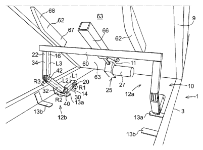
The furniture device 1 is now to be described with reference to
figure la-lb. The pivoting member 10 comprises a pivot arm 12a
and a further pivot arm 12b. The two pivot arms 12a, 12b are
arranged so that they extend essentially parallel with two oppo-
site directed sides of the furniture device 1. The two pivot arms
12a, 12b have essentially the same structural design.
The furniture device 1 further comprises a first support 13a and
a second support 13b for each of the pivot arms 12a, 12b. The
first support 13a and the second support 13b protrude out from
the fundament 3. The first support 13a and the second support
13b are adapted to support the pivot arm 12a, 12b while pivoting
the furniture device and while being in a stationary position.
Each of the pivot arms 12a, 12b comprise a first end 14 and a
second end 16. The pivoting member 10 further comprises a first
pivot 20, which first pivot 20 is connecting the first end 14 of
each of the pivot arm 12a and the further pivot arm 12b to the
fundament 3. The first pivot 20 is adapted to allow a first rota-
tion R1 of the pivot arms 12a, 12b in relation to the fundament
3.
CA 02817993 2013-05-15
WO 2012/072336 PCT/EP2011/068448
12
Each of the pivot arm 12a and the further pivot arm 12b com-
prises an elongated first arm 30, an elongated second arm 32
and an elongated third arm 34. The first arm 30 is closer to the
first pivot 20 than the second arm 32.
The first arm 30 and the second arm 32 is connected by means
of a second pivot 40, which second pivot 40 is adapted to allow
a second rotation R2 of the second arm 32 in relation to the first
arm 30.
Each of the pivot arm 12a and the further pivot arm 12b com-
prises a third pivot 42, which third pivot 42 is adapted to con-
nect the third arm 34 to the second arm 32. The third pivot 42 is
adapted to allow a third rotation R3 of the third arm 34 in rela-
tion to the second arm 32.
The first arm 30 is adapted to be supported by the first support
13a. The second arm 32 is adapted to be supported by the sec-
ond support 13b.
The pivoting member 10 further comprises a connection element
60. The second ends 16 of the pivot arm 12a and the further
pivot arm 12b are connected by means of the connection ele-
ment 60.
The pivoting member 10 further comprises two guide members
62. Each of the guide members 62 comprises a wedge formed
member that is attached to a lower surface 63 of the second
section 9, which lower surface is directed towards the funda-
ment 3 when the device 1 is oriented in the first orientation. The
guide member 62 comprises an inner portion 67 and outer por-
tion 68. The inner portion 67 is located closer to the motor unit
27 than the outer portion 68.
Moreover, the furniture device 1 comprises a link arm 11 The
link arm 11 extends from a fourth pivot 15 between the link arm
CA 02817993 2013-05-15
WO 2012/072336 PCT/EP2011/068448
13
11 and the outer part 22 of the pivot arm 12a to a fifth pivot 17
between the link arm 11 and the second section 9.
By means of the fourth pivot 15 and the fifth pivot 17 the second
section 9 is adapted to be to be pivoted independently from the
pivoting movement provided by the pivoting member 10. By
means of the link arm 11, it is assured that a person is not
pinched between the second section 9 and the fundament 3. A
person located between the second section 9 and the fundament
3 will only be subjected to the weight of the second section 9.
Thereby, no sensors are necessary to avoid a person from being
pinched between the second section 9 and the fundament 3.
The connection element 60 is adapted to slide on the guide
member 62, wherein the guide member 62 guides the pivoting
movement of the second section 9 in relation to the first section
7.
The pivoting member 10 further comprises a pivoting mechanism
25, which pivoting mechanism 25 is adapted to induce the first
rotation R1, the second rotation R2 and the third rotation R3.
The pivoting mechanism 25 comprises a motor unit 27, such as
an electric motor. The motor unit 27 is attached to the lower sur-
face 63 of the second section 9. The lower surface 63 of the
second section 9 is directed towards the fundament 3 when the
device 1 is oriented in the first orientation.
The motor unit 27 is adapted to act on an outer part 22 of the
pivot arms 12a 12b so that the second section 9 is pivoted in
relation to the first section 7. The outer part 22 is located at the
second end 16 of the pivot arms 12a, 12b.
In the disclosed embodiment the pivoting mechanism 25 is
adapted to act on the connection element 60, which connection
element 60 is connected to the third arm 34. The pivoting
CA 02817993 2013-05-15
WO 2012/072336 PCT/EP2011/068448
14
mechanism 25 is adapted to pull or push the outer part 22 to-
wards or away from the motor unit 27.
The connection element 60 comprises a groove 64 adapted to
be connected to a displacement member 66, such as a screw,
guide rail, etcetera. The displacement member is powered by
the motor unit 27, wherein the connection element 60 is dis-
placed toward or away from the motor unit 27.
Figure 2a-2c presents different views of the pivot arm 12a, the
further pivot arm 12b and the connection element 60. The first
arm 30 extends along a first longitudinal axis L1.
The second arm 32 extends along a second longitudinal axis L2.
The second rotation R2 is adapted to be initiated when the sec-
ond longitudinal axis L2 is essentially parallel with the first lon-
gitudinal axis L1 or oriented up to at a first angle C1 with the
first longitudinal axis L1, see fig. 4 and 5.
The first rotation R1 is adapted to be initiated when the second
longitudinal axis L2 is oriented at a second angle C2 with the
first longitudinal axis L1, see fig. 5 and 6. The second angle C2
is larger than the first angle C1.
The second arm 32 comprises a first stop member 70 which first
stop member 70 is adapted to stop the second rotation R2 at a
first inclination B1 between the second longitudinal axis L2 and
the first longitudinal axis L1. The first stop member 70 protrudes
away from the second longitudinal axis L2 of the second arm 32.
The first stop member 70 comprises a first side part 71 which
first side part 71 is adapted to abut the first arm 30 at the first
inclination B1 between the second longitudinal axis L2 and the
first longitudinal axis L1. See fig. 2a.
The third arm 34 extends along a third longitudinal axis L3. The
third rotation R3 is adapted to be initiated when the third longi-
CA 02817993 2013-05-15
WO 2012/072336 PCT/EP2011/068448
tudinal axis L3 is essentially parallel with the second longitudi-
nal axis L2 or oriented up to at a third angle C3 with the second
longitudinal axis L2, see Fig. 3 and 4.
5 The second rotation R2 is adapted to be initiated when the third
longitudinal axis L3 is oriented at a fourth angle C4 with the
second longitudinal axis L2, wherein the fourth angle C4 is lar-
ger than the third angle C3, see fig. 4. The fourth angle C4 is
larger than the third angle C3.
The third arm 34 comprises a second stop member 72 which
second stop member 72 is adapted to stop the third rotation R3
at the second inclination B2 between the third longitudinal axis
L3 and the second longitudinal axis L2.
The second stop member 72 protrudes away from the third lon-
gitudinal axis L3 of the third arm 34. The second stop member
72 comprises a second side part 73 which second side part 73 is
adapted to abut the second arm 32 at the second inclination B2
between the third longitudinal axis L3 and the second longitudi-
nal axis L2. See fig. 4.
In Fig. 2a the first second longitudinal axis L1, the second longi-
tudinal axis L2 and the third longitudinal axis L3 are essentially
parallel. Accordingly, the pivot arm 12a positioned so that the
second section 9 is in the first orientation.
In fig. 2b the first second longitudinal axis L1, the second longi-
tudinal axis L2 and the third longitudinal axis L3 are non-parallel
and the second rotation R2 and third rotation R3 is stopped in
the first inclination B1 and the second inclination B2 respec-
tively. Accordingly, the pivot arm 12a is positioned so that the
second section 9 is in essentially the third orientation.
CA 02817993 2013-05-15
WO 2012/072336 PCT/EP2011/068448
16
In fig. 2c the pivot arm 12a and the further pivot 12b arm is
shown from a top view. The two pivot arms 12a, 12b is con-
nected by the connection member 60.
The motor unit 27 is attached to the lower surface 63 of the sec-
ond section 9. From the first orientation the motor unit 27 is
adapted to pull the outer part 22 of each of the pivot arms 12a,
12b so that the third rotation R3 is induced, which third rotation
R3 rotates the second section 9 from the first orientation to the
second orientation.
From the second orientation the motor unit 27 is adapted to pull
the outer part 22 of each of the pivot arms 12a, 12b so that the
second rotation R2 is induced, which second rotation R2 rotates
the second section 9 from the second orientation to the third
orientation.
From the third orientation the motor unit 27 is adapted to pull
the outer part 22 of each of the pivot arms 12a, 12b so that the
first rotation R1 is induced, which first rotation R1 rotates the
second section 9 from the third orientation to the fourth orienta-
tion.
Figure 3-6 shows side views of the furniture device in fig. 1,
where the second section 9 is arranged in the first, the second,
the third and the forth orientation respectively. The pivot arm
12a, 12b is shown in solid line and dashed line in fig. 4-6. The
solid line represents the real position of the pivot arm 12a, 12b
in the figure. The dashed line in fig. 4-6 represents the position
of the pivot arm 12a, 12b in the previous figure.
The arrow between the pivot arm 12a, 12b in solid line and
dashed line represents how the arms 30, 32, 34 of the pivot arm
12a, 12b are rotated by means of the third rotation R3 (as from
fig. 3 to fig. 4), the second rotation R2 (as from fig. 4 to fig. 5)
and the first rotation R1 (as from fig. 5 to fig. 6).
CA 02817993 2013-05-15
WO 2012/072336 PCT/EP2011/068448
17
In figure 3 the second section 9 is oriented in the first orienta-
tion. The pivoting mechanism 25 is adapted to act on the outer
part 22 of a pivot arm 12 so that a third rotation R3 is induced.
The third rotation R3 rotates the second section 9 from the first
orientation to the second orientation.
In figure 4 the second section 9 is oriented in the second orien-
tation. In the second orientation the second section 9 is inclined
at the first angle Al with the first plane P1. The pivoting mecha-
nism 25 is adapted, from the second orientation, to act on the
outer part 22 of the pivot arm 12 so that the second rotation R2
is induced. The second rotation R2 rotates the second section 9
from the second orientation to a third orientation.
In figure 5 the furniture device 1 is oriented in the third orienta-
tion. In the third orientation the second section 9 is inclined at a
second angle A2 with the first plane P1, wherein the second an-
gle A2 is higher than the first angle Al. The pivoting mechanism
25 is adapted, from the third orientation, to act on the outer part
22 of a pivot arm 12 so that the first rotation R1 rotates the sec-
ond section 9 from the third orientation to a fourth orientation.
In figure 6 the furniture device 1 is oriented in the forth orienta-
tion. In the fourth orientation the second section 9 in inclined at
a third angle A3 with the first plane P1, wherein the third angle
A3 is higher than the second angle A2. In an embodiment of the
invention, the second section is adapted to be pivoted so that
the third angle A3 becomes 90 degrees.
The present invention is not limited to the embodiments dis-
closed but may be varied and modified within the scope of the
following claims.