Note: Descriptions are shown in the official language in which they were submitted.
CA 02818665 2013-05-21
WO 2012/071355
PCT/US2011/061739
HIGH-SPEED EXPANDED CONTENT LABELS
CROSS-REFERENCE TO RELATED APPLICATIONS
[0001] This present application claims the benefit and priority of U.S.
provisional patent application number 61/458,299, entitled "High-Speed, Low
Cost Expanded Content Label," filed on November 22, 2010, which is
incorporated herein by reference in its entirety.
FIELD OF THE INVENTION
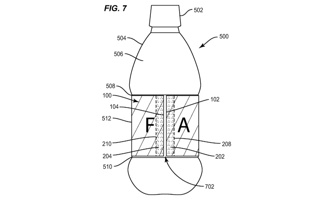
[0002] The present invention is directed generally to labels, and more
specifically to methods of applying multiple high-speed expanded content
labels
to an object.
CA 02818665 2013-05-21
WO 2012/071355
PCT/US2011/061739
SUMMARY
[0003] The present application is directed to methods for applying multiple
labels to an object. An exemplary method comprises affixing an inner label to
the
object. A non-resealable adhesive may be applied to a leading edge of an outer
label. The outer label leading edge may be affixed to the inner label. A
resealable adhesive may be applied to a trailing edge of the outer label, and
the
outer label trailing edge may be releasably coupled to the outer label leading
edge. At least a portion of the inner label may be obscured from view.
2
CA 02818665 2013-05-21
WO 2012/071355
PCT/11S2011/061739
BRIEF DESCRIPTION OF THE DRAWINGS
[0004] Figure 1 is a front view of an exemplary label according to various
embodiments.
[0005] Figure 2 is a back view of an exemplary label according to various
embodiments.
[0006] Figure 3 is a front view of an exemplary label according to various
embodiments.
[0007] Figure 4 is a back view of an exemplary label according to various
embodiments.
[0008] Figure 5A illustrates a leading edge of an exemplary label affixed
to a
container according to various embodiments.
[0009] Figure 5B illustrates an exemplary label secured about a container
according to various embodiments.
[0010] Figure 6 illustrates an exemplary label secured about a container
according to various embodiments.
[0011] Figure 7 illustrates an exemplary inner label secured about a
container
according to various embodiments.
[0012] Figure 8 illustrates a leading edge of an exemplary outer label
affixed
to an exemplary inner label according to various embodiments.
[0013] Figure 9 illustrates an exemplary outer label affixed to an
exemplary
inner label and partially wrapped about a container according to various
embodiments.
[0014] Figure 10 illustrates an exemplary outer label with a window affixed
to
an exemplary inner label and partially wrapped about a container according to
various embodiments.
3
CA 02818665 2013-05-21
WO 2012/071355
PCT/US2011/061739
[0015] Figure 11 illustrates an exemplary outer label with a window secured
about a container and a portion of an inner label visible through the window
according to various embodiments.
[0016] Figure 12 is an exemplary flow diagram of a method for applying
multiple labels to an object according to various embodiments.
[0017] Figure 13 is an exemplary flow diagram of a method for applying
multiple labels to an object according to various embodiments.
[0018] Figure 14 is an exemplary flow diagram of a method for applying
multiple labels to an object according to various embodiments.
[0019] Figure 15 is an exemplary flow diagram of a method for applying
multiple labels to an object according to various embodiments.
4
CA 02818665 2013-05-21
W02012/071355
PCT/US2011/061739
DETAILED DESCRIPTION
[0020] The present application is directed to methods for applying multiple
labels to an object. An exemplary method comprises affixing an inner label to
the
object using adhesive from a first adhesive application device. A non-
resealable
adhesive or a breakaway adhesive from a second adhesive application device
may be applied to a leading edge of an outer label. The outer label leading
edge
may be affixed to the inner label. A resealable adhesive from a third adhesive
application device may be applied to a trailing edge of the outer label, and
the
outer label trailing edge may be releasably coupled to the outer label leading
edge. At least a portion of the inner label may be obscured from view.
[0021] Figure 1 illustrates various embodiments of a front surface 108 of
an
inner label 100 for an object according to various embodiments. The inner
label
100 comprises a leading edge 102 and a trailing edge 104. While the leading
edge
102 is oriented to the left and the trailing edge is oriented to the right as
presented in Figure 1, the orientation of the leading edge 102 and the
trailing
edge 104 could be reversed depending on which edge is first applied to the
object. Both orientations are within the scope of the present disclosure.
Inner
label front surface 108 may comprise writing or other indicia 106 thereon.
[0022] As used herein, the leading edge refers to the first edge to be
affixed to
the object and the trailing edge refers to the second edge to be affixed to
the
object of the overlapping leading edge. Depending on the orientation of the
label
and the container when the label is affixed to the object, either edge of the
label
may be the leading edge. The orientations presented in the figures are for
convenience and are not intended to be limiting in any way.
[0023] Figure 2 illustrates various embodiments of a back surface 206 of
the
inner label 100. In various embodiments, the inner label back surface 206
CA 02818665 2013-05-21
WO 2012/071355
PCT/US2011/061739
comprises two strips of adhesive 202 and 204 on or immediately adjacent to the
leading and trailing edges, 102 and 104, respectively. Inner label leading
edge
adhesive 202 may have a boundary 208 defined as its limit on the inner label
back surface 206. Inner label trailing edge adhesive 204 may also have a
boundary 210. While Figure 2 illustrates that the adhesive strips 202 and 204
are
generally close to the inner label leading and trailing edges 102 and 104,
respectively, it is understood that the adhesive strips 202 and 204 may be
continuous or discontinuous, and may extend across any portion of the inner
label back surface 206, including the entire inner label back surface 206. In
various embodiments, a length of the inner label 100 may be selected to be
slightly longer than a circumference of the object on which it is placed, such
that
the trailing edge 104 overlaps the leading edge 102, and the trailing edge 104
is
affixed to the leading edge 102. In various embodiments, the length of the
inner
label 100 may be selected to be approximately the same as the circumference of
the object on which it is placed, such that the leading edge 102 and the
trailing
edge 104 do not overlap.
[0024] Figure 3 illustrates various embodiments of a front surface 306 of
an
outer label 300. Outer label 300 comprises a leading edge 302 and a trailing
edge
304, and indicia 308 may be imprinted on the outer label front surface 306.
[0025] Various embodiments of a back surface 402 of the outer label 300 are
illustrated in Figure 4. The outer label back surface 402 may comprise various
indicia 408 printed thereon, as well as two strips of adhesive 404 and 406 on
or
immediately adjacent to the leading and trailing edges, 302 and 304,
respectively.
Outer label leading edge adhesive 404 may have a boundary 410 defined as its
limit on the outer label back surface 402. Outer label trailing edge adhesive
406
may also have a boundary 412. While Figure 4 illustrates that the adhesive
strips
404 and 406 are generally close to the outer label leading and trailing edges
302
6
CA 02818665 2013-05-21
WO 2012/071355
PCT/US2011/061739
and 304, respectively, it is understood that the adhesive strips 404 and 406
may
be continuous or discontinuous, and may extend across any portion of the outer
label back surface 402, including the entire outer label back surface 402. In
various embodiments, the adhesive strips 404 and 406 are confined to areas
near
the leading and trailing edges 302 and 304, respectively, so as not to obscure
or
interfere with the outer label back surface indicia 408.
[0026] The inner label adhesive 202, 204 and the outer label adhesive 404,
406
may be applied in a variety of patterns as can be appreciated by one skilled
in the
art. The adhesive 202, 204, 404, 406 may be applied in in strips, dots,
droplets,
circles, rectangles, squares, triangles, lines, and the like, as well as
combination of
patterns.
[0027] A length of the outer label 300 may be selected to be slightly
longer
than a circumference of the object on which it is placed, such that the outer
label
trailing edge 304 overlaps the outer label leading edge 302, and the outer
label
trailing edge 304 is affixed to the outer label leading edge 302. In various
embodiments, the length of the outer label 300 may be selected to be
approximately the same as the circumference of the object on which it is
placed,
such that both the leading edge 302 and the trailing edge 304 do not overlap
and
are affixed to the inner label front surface 108.
[0028] Figure 5A illustrates the application of the inner label 100 to an
exemplary container 500 according to various embodiments. The container 500
may be a glass or plastic bottle, or other type of container such as a metal
can or a
cardboard receptacle. The container may be round, rectangular, square, or any
other shape known in the art. The term "container" is used here for
convenience
to describe exemplary embodiments. It is understood that the container may be
any object, including non-containers. Container 500 may comprise a cap 502
removably secured to a body 504. Various embodiments of the body 504 may
7
CA 02818665 2013-05-21
WO 2012/071355
PCT/US2011/061739
have an exterior surface 506 that comprises a top label panel 508, a bottom
label
panel 510, and a recessed surface 512 interposed between the top label panel
508
and the bottom label panel 510. As discussed below, the inner label 100 may be
applied to the container 500 at the recessed area 512 between the top label
panel
508 and the bottom label panel 510.
[0029] In various embodiments, the outer label 300 may be rotatable about the
inner label 100, as discussed below. In these embodiments, the top label panel
508 and bottom label panel 510 may function to restrict upward and downward
movement of the outer label 300 in relation to the container 500 such that the
outer label 300 generally remains in a position covering the inner label 100.
The
top label panel 508 and bottom label panel 510 may be excluded from
embodiments in which the outer label does not rotate, although such exclusion
is
not required.
[0030] Figure 5B illustrates the container 500 with the inner label 100
affixed
to the container 500. Initially, as illustrated in Figure 5A, inner label
leading edge
102 is placed in contact with the recessed surface 512 of the container 500
and
affixed to the container 500 by the leading edge adhesive strip 202. With
relative
motion between the container 500 and the inner label 100, the inner label 100
may
be wrapped around the container 500 with the inner label trailing edge 104 now
overlapping the inner label leading edge 102 such that the leading edge
adhesive
strip 202 holds the inner label leading edge 102 to the container 500 while
the
trailing edge adhesive strip 204 holds the inner label trailing edge 104 to
the
overlapped inner label leading edge 102.
[0031] In various embodiments as illustrated in Figure 6, the length of the
inner label 100 may be substantially the same as a circumference of the
recessed
surface 512 of the container 500, which may allow the inner label leading edge
102 and inner label trailing edge 104 to abut rather than overlap. However, it
is
8
CA 02818665 2013-05-21
WO 2012/071355
PCT/US2011/061739
also possible that the length of the inner label 100 may be shorter than the
circumference of the recessed surface 512, resulting in a gap 702 between the
inner label leading edge 102 and the inner label trailing edge 104 when the
inner
label is affixed to the recessed surface as illustrated in Figure 7. In both
of these
instances, the inner label trailing edge adhesive strip 204 may adhere to the
recessed surface 512 of the container 500, rather than the inner label leading
edge
102.
[0032] In various embodiments, the inner label adhesive strips 202, 204 may
be comprised of a permanent adhesive. In general, a permanent adhesive is one
that does not readily release from a surface to which it adheres after the
adhesive
dries or cures. Using the inner label 100 as an example, the permanent
adhesive
202, 204 will tend not to release from the recessed surface 512, nor will it
tend to
release the inner label leading edge 102 or trailing edge 104 once dried or
cured.
In order to remove the inner label from the recessed surface 512, the inner
label
100 may have to be torn from the adhesive, or the adhesive layer 202, 204 may
have to be fractured which may leave some of the adhesive on the recessed
surface 512 and some of the adhesive on the inner label leading edge 102 or
trailing edge 104. Once the surfaces affixed with the permanent adhesive are
separated, they may not be reattached.
[0033] Figure 8 illustrates the container 500 with the inner label 100
already
affixed to the recessed surface 512. In various embodiments, the outer label
300
may be mounted over the inner label 100 on the container 500, thereby
obscuring
at least a portion of the inner label 100 from view. In various embodiments,
the
entire inner label 100 is obscured from view when the outer label 300 is
mounted
over the inner label 100. The outer label 300 may be wider than the inner
label
100, although in certain embodiments a width of the outer label 300 may be
equal
to or less than a width of the inner label 100.
9
CA 02818665 2013-05-21
WO 2012/071355
PCT/US2011/061739
[0034] Figure 8 illustrates the application of the outer label 300 over the
inner
label 100 on the container 500 according to various embodiments. The outer
label leading edge 302 may be placed in contact with any portion of the inner
label front surface 108 and affixed to the inner label front surface 108 by
the outer
label leading edge adhesive strip 404. With relative motion between the
container 500 and the outer label 300, the outer label 300 may be wrapped
around the container 500 with the outer label trailing edge 304 now
overlapping
the outer label leading edge 302 such that the outer label leading edge
adhesive
strip 404 holds the outer label leading edge 302 to the inner label 100 while
the
outer label trailing edge adhesive strip 406 holds the outer label trailing
edge 304
to the overlapped outer label leading edge 302.
[0035] As described previously for the inner label 100, in various
embodiments a length of the outer label may be selected such that the outer
label
trailing edge 304 overlaps the outer label leading edge 302. A different
length
may be selected for the outer label 300 such that the outer label leading edge
302
and trailing edge 304 abut when mounted on the container, or that a gap is
formed between the outer label leading edge 302 and trailing edge 304.
[0036] Figure 9 illustrates the operation of the inner label 100 and the
outer
label 300 according to various embodiments. Beginning with the container 500
with the inner label 100 and the outer label 300 in place as shown, for
example, in
Figure 6, the outer label trailing edge 304 may be detached from the outer
label
leading edge 302 and at least partially peeled back as shown in Figure 9. The
combination of the inner label 100 and the outer label 300 in this
configuration
effectively triples the amount of surface area available for viewing by a
consumer
or user of the container 500. Prior to detaching the outer label trailing edge
304,
the consumer may view the outer label front surface 306. Upon detaching the
outer label trailing edge 304, the consumer may now view the outer label back
CA 02818665 2013-05-21
WO 2012/071355
PCT/US2011/061739
surface 402 and the inner label front surface 108 in addition to the outer
label
front surface 306.
[0037] One of at least three types of adhesive may be used for the outer
label
leading edge adhesive 404. A first type of adhesive is the permanent adhesive
as
described above for the inner label 100. When a permanent adhesive is used for
the outer label leading edge adhesive 404, the outer label leading edge
generally
cannot be detached without inflicting damage to one or both of the outer label
300 or the inner label 100. This may be desirable for various embodiments
where
the outer label 300 is not intended to be removed from the container 500.
[0038] A second type of adhesive that may be used for the outer label
leading
edge adhesive 404 is a releasable adhesive. A releasable adhesive is one that
will
release from a surface to which it is attached once a sufficient mechanical
force is
applied. A releasable adhesive may be used when the outer label back surface
402 comprises a coupon for a subsequent purchase of a product. The releasable
adhesive may allow the consumer to easily remove the outer label 300 for later
use. In various embodiments, the releasable adhesive may be a breakaway
adhesive. A breakaway adhesive may have limited ability to withstand shear
stresses. Shear stresses may cause the adhesive bond created between the label
(e.g., outer label 300) and the surface to which it is affixed (e.g., the
inner label
100 or container 500) to fail along the adhesive. In general, a releasable or
breakaway adhesive may not re-attach to a surface once removed.
[0039] A third type of adhesive that may be used for the outer label
leading
edge adhesive 404 is a resealable adhesive. A resealable adhesive may release
from a surface to which it is attached once a sufficient mechanical force is
applied, similar to the releasable adhesive described above. However, the
resealable adhesive may be re-attached to a surface by applying pressure. A
resealable adhesive may be desirable when the outer label back surface 402 or
the
11
CA 02818665 2013-05-21
WO 2012/071355
PCT/US2011/061739
inner label front surface 108 comprise information that may be needed only on
occasion. Thus, the consumer or user may detach the outer label 300 when the
information is needed, then re-attach the outer label 300.
[0040] In various embodiments, the outer label trailing edge adhesive 406
may be a releasable adhesive or a resealable adhesive, depending on the
intended use of the outer label 300. As described above, if the surfaces 108,
402
comprise information that is intended to stay with the container, the outer
label
trailing edge adhesive 406 may be a resealable adhesive. In contrast, if the
outer
label 300 is intended to be removed from the container 500, a releasable
adhesive
may be desirable.
[0041] Figure 10 illustrates various embodiments of the outer label 300
comprising a window 1002. The window 1002 may comprise a void in the outer
label 300 such that a portion of the inner label 100 may be visible through
the
window. In various embodiments, the window 1002 may have a transparent
covering (not shown). In various other embodiments, the window may comprise
a transparent section of the outer label 300 itself rather than a void. Figure
10
illustrates the outer label 300 partially wrapped about a container 1000, and
inner
label 100 already in place on the container 1000. As shown, the outer label
leading edge adhesive 404 maintains the outer label 300 coupled to the inner
label 100. The outer label 300 may then be moved from the position illustrated
in
Figure 10 to the position illustrated in Figure 11 to secure the outer label
300
about the container 1000. Outer label trailing edge adhesive 406 may couple to
the outer label leading edge 302 if the outer label leading edge 302 and
trailing
edge 304 overlap; otherwise, the outer label trailing edge adhesive 406 may be
coupled to the inner label front surface 108.
[0042] Once the outer label 300 is in position on the container 1000 as
illustrated in Figure 11, at least a portion of the inner label front surface
indicia
12
CA 02818665 2013-05-21
WO 2012/071355
PCT/US2011/061739
106 may be visible through the window 1002. This may allow viewing of a first
portion of the inner label 100 without removing the outer label 300. In
various
embodiments, the outer label leading edge adhesive 404 may be a breakaway
adhesive. Rotation of the outer label 300 relative to the inner label 100 may
exert
shear stresses on the breakaway adhesive, causing the adhesive bond affixing
the
outer label leading edge 302 to the inner label 100 to fail. The outer label
300 may
then be freely rotatable about the inner label, and a second portion of the
inner
label 100 may be visible when the outer label 300 is rotated to a second
position.
The window 1002 may be rectangular as illustrated in Figures 10 and 11, or any
other shape as needed for a particular application. For example, the window
1002 may be a slit that reveals an alphanumeric string on the inner label 100.
In
various embodiments, the outer label 300 may comprise more than one window
1002. Various embodiments in which the outer label trailing edge adhesive 406
is
a resealable or releasable adhesive may allow the outer label to be peeled
back to
reveal the outer label back surface 402 and the entire inner label front
surface 108
or to be removed from the container 1000, in addition to being rotatable.
[0043] Figure 12 illustrates a general flow chart of various embodiments of
a
method 1200 for applying multiple labels to an object. The method 1200 may be
employed with roll-fed labels. An inner label 100 may be affixed to an object,
such as a container 500, using adhesive from a first adhesive application
device
(step 1205). In various embodiments, the adhesive may be a permanent
adhesive. A second adhesive application device may be used to apply a non-
resealable adhesive to a leading edge 302 of an outer label 300 (step 1210).
The
outer label leading edge 302 may be affixed to the inner label 100 (step
1215), for
example by placing the outer label leading edge 302 in physical contact with
the
inner label 100 and applying pressure. A resealable adhesive may be applied
from a third adhesive application device to a trailing edge 304 of the outer
label
13
CA 02818665 2013-05-21
WO 2012/071355
PCT/US2011/061739
300 (step 1220). The outer label trailing edge 304 may then be releasably
coupled
to the outer label leading edge 302 (step 1225). In various embodiments, the
resealable adhesive may allow the outer label trailing edge 304 to be
repeatedly
coupled and decoupled to the outer label leading edge 302, thereby revealing
the
inner label 100 and an outer label back surface 402 when the outer label
trailing
edge is decoupled. In the decoupled stage, a revealed surface space may be
tripled or nearly tripled compared to the coupled stage.
[0044] Figure 13 illustrates a general flow chart of various embodiments of
a
method 1300 for applying multiple labels to an object. The method 1300 may be
employed with roll-fed labels, and various embodiments may comprise a
rotatable outer label. An inner label 100 may be affixed to an object, such as
a
container 500, using adhesive from a first adhesive application device (step
1305).
In various embodiments, the adhesive may be a permanent adhesive. A second
adhesive application device may be used to apply a non-resealable adhesive to
a
leading edge 302 of an outer label 300 (step 1310). In various embodiments,
the
non-resealable adhesive may be a breakaway adhesive. The outer label leading
edge 302 may be releasably coupled to the inner label 100 (step 1315), for
example by placing the outer label leading edge 302 in physical contact with
the
inner label 100 and applying pressure. A resealable adhesive may be applied
from a third adhesive application device to a trailing edge 304 of the outer
label
300 (step 1320). The outer label trailing edge 304 may then be releasably
coupled
to the outer label leading edge 302 (step 1325).
[0045] In various embodiments of method 1300 in which the outer label
leading edge adhesive 404 is a breakaway adhesive, rotation of the outer label
300 relative to the inner label 100 may cause the adhesive bond between the
outer
label leading edge 302 and the inner label 100 to fail. Since the outer label
300 is
14
CA 02818665 2013-05-21
WO 2012/071355
PCT/US2011/061739
no longer attached to the inner label 100 (but remains wrapped around the
inner
label 100), the outer label 300 may be free to rotate relative to the inner
label 100.
[0046] Figure 14 illustrates a general flow chart of various embodiments of
a
method 1400 for applying labels to an object. The method 1400 may be
employed with cut and stack labels. An inner label 100 may be affixed to an
object, such as a container 500, using adhesive from a first adhesive
application
device (step 1405). In various embodiments, the adhesive may be a permanent
adhesive. A second adhesive application device may be used to apply a non-
resealable adhesive to a front surface 108 of the inner label 100 (step 1410).
The
outer label leading edge 302 may be affixed to the inner label 100 (step
1415), for
example by placing a back surface 402 of the outer label leading edge 302 in
physical contact with the non-resealable adhesive and applying pressure. A
resealable adhesive may be applied from a third adhesive application device to
the outer label leading edge 304 on a front surface 306 of the outer label 300
(step
1420). The outer label trailing edge 304 may then be releasably coupled to the
outer label leading edge 302 (step 1425). In various embodiments, the
resealable
adhesive may allow the outer label trailing edge 304 to be repeatedly coupled
and decoupled to the outer label leading edge 302, thereby revealing the inner
label 100 and an outer label back surface 402 when the outer label trailing
edge is
decoupled. In the decoupled stage, a revealed surface space may be tripled or
nearly tripled compared to the coupled stage.
[0047] Figure 15 illustrates a general flow chart of various embodiments of
a
method 1500 for applying labels to an object. The method 1500 may be
employed with cut and stack labels, and various embodiments may comprise a
rotatable outer label. An inner label 100 may be affixed to an object, such as
a
container 500, using adhesive from a first adhesive application device (step
1505).
In various embodiments, the adhesive may be a permanent adhesive. A second
CA 02818665 2013-05-21
WO 2012/071355
PCT/15S2011/061739
adhesive application device may be used to apply a non-resealable adhesive to
a
front surface 108 of the inner label 100 (step 1510). In various embodiments,
the
non-resealable adhesive may be a breakaway adhesive. The outer label leading
edge 302 may be affixed to the inner label 100 (step 1515), for example by
placing
a back surface 402 of the outer label leading edge 302 in physical contact
with the
non-resealable adhesive and applying pressure. A resealable adhesive may be
applied from a third adhesive application device to the outer label leading
edge
304 on a front surface 306 of the outer label 300 (step 1520). The outer label
trailing edge 304 may then be releasably coupled to the outer label leading
edge
302 (step 1525).
[0048] In various embodiments of method 1500 in which the outer label
leading edge adhesive 404 is a breakaway adhesive, rotation of the outer label
300 relative to the inner label 100 may cause the adhesive bond between the
outer
label leading edge 302 and the inner label 100 to fail. Since the outer label
300 is
no longer attached to the inner label 100 (but remains wrapped around the
inner
label 100), the outer label 300 may be free to rotate relative to the inner
label 100.
[0049] Spatially relative terms such as "under", "below", "lower", "over",
,'upper", and the like, are used for ease of description to explain the
positioning
of one element relative to a second element. These terms are intended to
encompass different orientations of the device in addition to different
orientations than those depicted in the figures. Further, terms such as
"first",
"second", and the like, are also used to describe various elements, regions,
sections, etc. and are also not intended to be limiting. Like terms refer to
like
elements throughout the description.
[0050] As used herein, the terms "having", "containing", "including",
"comprising", and the like are open ended terms that indicate the presence of
stated elements or features, but do not preclude additional elements or
features.
16
CA 02818665 2013-05-21
WO 2012/071355
PCT/US2011/061739
The articles "a", "an" and "the" are intended to include the plural as well as
the
singular, unless the context clearly indicates otherwise.
[0051] The present invention may be carried out in other specific ways than
those herein set forth without departing from the scope and essential
characteristics of the invention. The present embodiments are, therefore, to
be
considered in all respects as illustrative and not restrictive, and all
changes
coming within the meaning and equivalency range of the appended claims are
intended to be embraced therein.
17