Note: Descriptions are shown in the official language in which they were submitted.
CA 02818830 2013-05-23
WO 2012/069541 PCT/EP2011/070821
DOWNHOLE SYSTEM HAVING A WIRELESS UNIT
Field of the invention
The present invention relates to a downhole system comprising a casing having
an inner wall. Furthermore, the downhole system comprises a wireless unit
which
is movable within the casing, comprising driving means in the form of wheels
and
at least one battery pack.
Background art
During oil production, it may become necessary to perform maintenance work in
a well or to open a production well. Such well work is known as well
intervention.
A production casing is arranged inside the well and is closed by a well head
in its
upper end. The well head may be placed on shore, on an oil rig or on the
seabed.
In order to lower and raise the tool into and out of the well and supply the
tool
with electricity, the tool is connected to a wireline at its top, which is fed
through
the well head. In order to seal the well while performing the operation using
the
tool, the wireline passes through a high-pressure grease injection section and
sealing elements for sealing around the wireline.
In order to seal around the wireline as it passes through the grease injection
sec-
tion, high-pressure grease is pumped into the surrounding annulus to effect a
pressure-tight dynamic seal which is maintained during the operation by
injecting
more grease as required. A slight leakage of grease is normal, and the
addition of
fresh grease allows for the consistency of the seal to be maintained at an
effec-
tive level. In this way, grease leaks from the grease injection section into
the sea
during an intervention operation, which is not environmentally desirable. Due
to
the increasing awareness of the environment, there is a need for a more envi-
ronmentally friendly solution.
Summary of the invention
It is an object of the present invention to wholly or partly overcome the
above
disadvantages and drawbacks of the prior art. More specifically, it is an
object to
CA 02818830 2013-05-23
WO 2012/069541 PCT/EP2011/070821
2
provide an improved wireless tool for operating in a well without requiring
the
use of a wireline or a similar powerline.
The above objects, together with numerous other objects, advantages, and fea-
tures, which will become evident from the below description, are accomplished
by
a solution in accordance with the present invention by a downhole system com-
prising:
- a casing having an inner wall, and
- a wireless unit which is movable within the casing, comprising driving
means in
the form of wheels and at least one battery pack comprising at least one
battery
for powering an electrical motor driving a pump driving the wheels to rotate
along the inner wall of the casing, wherein the downhole system further
compris-
es a well head having a sound detection device for detecting vibrations in the
casing, e.g. caused by the driving means or an operation performed by the wire-
less unit.
In one embodiment, the sound detection device may be a geophone.
Also, the sound detection device may be arranged in contact with the casing.
In this way, the personnel operating the unit are able to determine the
position of
the unit without communicating directly with the wireless unit. Furthermore,
when the driving means of the wireless unit pass a casing collar, the
difference in
sound or vibrations can be detected, thereby enabling calculation of the
position
of the wireless unit based on the number of casing collars passed by the unit.
Furthermore, if the wireless unit accidentally stops due to an unexpected hin-
drance, the operator will be informed and can then retract the unit and start
over.
Having a sound detection device provides an extra precautionary measure to en-
sure that the wireless unit is in position for performing an operation or is
suffi-
ciently close to the downhole safety valve to open the valve and be let
through. If
other safety arrangement fails which is arranged downhole, these arrangements
are not easily replaced as they are situated in the well approximately 300
metres
down. However, replacing a sound detection device in the well head is easy,
and
it is even easier if the sound detection device is arranged on the other
surface of
the well head forming part of the outer surface.
CA 02818830 2013-05-23
WO 2012/069541 PCT/EP2011/070821
3
In addition, the downhole system may comprise a control device arranged in
communication with the wireless unit in the well and in communication with the
sound detection device to control the wireless unit based on the sound pattern
detection by the sound detection device.
Hereby, operations performed by the wireless unit can be monitored while per-
forming an operation. Thus, an operation not sounding according to the
specifica-
tion which is made from earlier performed similar operations can be stopped be-
fore the operation goes wrong, and the operation may possibly be started
again.
More importantly, an operation performed according to the sound specification
can prove to the operator that the operation was performed correctly. Thus,
hav-
ing a sound detection device allows for the possibility of stopping an
operation
before it goes wrong and ruins the well. Hence, the risk of an operation
causing
more damage than it actually solves is reduced.
The control device may be arranged in connection with the power box or at
least
in communication with the power box.
Furthermore, the wireless unit does not have to be able to communicate with
its
operator while being in the well as the operator is able to detect any actions
and
the wireless unit can be programmed to return after a certain amount of time
with the data representing the operation performed. When the wireless unit is
not
connected to a wireline, a grease connection head is unnecessary, which im-
proves the environmental safety.
Moreover, the sound detection device may comprise a display showing the vibra-
tions detected in the casing, e.g. in the form of a curve illustrating the
vibrations.
Furthermore, the detection device may comprise a transducer or sensor abutting
an outer wall of the well head.
Also, the sound detection device may be an acoustic-to-electric transducer or
sensor that converts sound into an electrical signal.
The transducer may be arranged at the top end of the well head.
CA 02818830 2013-05-23
WO 2012/069541 PCT/EP2011/070821
4
The downhole system may further comprise a processor for calculating a
distance
from the well head to the wireless unit.
Furthermore, the processor may communicate wirelessly with the detection de-
vice by means of acoustics, electromagnetics, Wi-Fi, ZigBee, wireless LAN,
DECT,
GSM, UWB, UMTS, Bluetooth, sonic or radio frequency.
In addition, the downhole system may further comprise a downhole safety valve
arranged in the casing.
In an embodiment, the detection device may be able to communicate with the
downhole safety valve and instruct it to open when the wireless unit is within
a
predetermined distance from the well head.
In another embodiment, the downhole system may further comprise a docking
station enabling the wireless unit to connect thereto in order to be charged
or re-
charged, or to upload or download information or signals to and from the
wireless
unit.
Moreover, the docking station may be arranged in the well head.
By having the docking station in the well head and not in a sidetrack, the
docking
station may be easily replaced. Furthermore, the well head does not have to be
of an increased diameter so as to also accommodate the insertion of a
sidetrack
when completing the well as in known solutions. When having a sidetrack, the
in-
ner diameter of the well head has to be larger than in a well without a
sidetrack
in order that the casing with sidetrack can be inserted into the well to make
the
well.
The wireless unit may comprise a wireless connection for transferring
electricity
and/or data to and from the wireless unit.
Furthermore, the well head may comprise a recharge connection for recharging
and/or transferring electricity and/or data to and from the wireless unit.
The recharge connection makes it unnecessary to let the wireless unit out of
the
fluid-tight well head or well for recharging.
CA 02818830 2013-05-23
WO 2012/069541 PCT/EP2011/070821
Moreover, the recharge connection may comprise an inductive coupling.
Additionally, the well head may comprise a tubular section having a wall
around
which the recharge connection is arranged, enabling recharging and/or transfer
5 of electricity and/or data to and from the wireless unit through the wall
of the
tubular section.
Also, the well head may comprise a tubular section having an end which has an
inner face and an outer face, and the recharge connection may be arranged at
the outer face of the end, enabling recharging and/or transfer of electricity
and/or data to and from the wireless unit through the end of the tubular
section.
Furthermore, the wireless unit may comprise an inductive coupling.
In an embodiment, the downhole system may further comprise a lubricator which
is connectable with the end of the tubular section, and wherein the recharge
con-
nection is arranged around the lubricator, enabling recharging and/or transfer
of
electricity and/or data to and from the wireless unit through a wall of the
lubrica-
tor.
Moreover, the downhole system may comprise a lubricator with an end having an
inner face and an outer face, which is connectable with the end of the tubular
section, and wherein the recharge connection is arranged at the outer face of
the
end of the lubricator, enabling recharging and/or transfer of electricity
and/or da-
ta to and from the wireless unit through the end wall of the lubricator.
In addition, the downhole system may comprise a recharge tool which is sub-
mergible in the casing.
Hereby, the wireless unit can be recharged without it being necessary to enter
the well head or lubricator, and the wireless unit thereby does not have to
waste
power travelling the distance from the recharge tool to the well.
The recharge tool may be submerged via a wireline or a powerline.
Furthermore, the recharge tool may comprise a recharge connection for recharg-
ing and/or transferring electricity and/or data to and from the wireless unit.
CA 02818830 2013-05-23
WO 2012/069541 PCT/EP2011/070821
6
In addition, the recharge connection may comprise an inductive coupling for re-
charging and/or transferring electricity and/or data to and from the wireless
unit.
Finally, the recharge tool may comprise a docking station enabling the
wireless
unit to connect with the wireless unit and be charged or recharged, or to
upload
or download information or signals to and from the wireless unit.
Brief description of the drawings
The invention and its many advantages will be described in more detail below
with reference to the accompanying schematic drawings, which for the purpose
of
illustration show some non-limiting embodiments and in which
Fig. 1 shows a wireless downhole unit arranged in a casing in a well,
Fig. 2 shows a well head having a sound detection device,
Fig. 3 shows a sound detection device,
Fig. 4 shows another embodiment of the well head having a recharge connection,
Fig. 5 shows yet another embodiment of the well head having a recharge connec-
tion, and
Fig. 6 shows a downhole system having a recharger tool, arranged in the
casing.
All the figures are highly schematic and not necessarily to scale, and they
show
only those parts which are necessary in order to elucidate the invention,
other
parts being omitted or merely suggested.
Detailed description of the invention
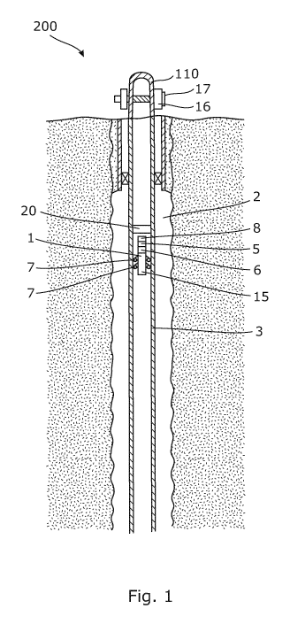
Fig. 1 shows a downhole system 200 comprising a wireless downhole unit 1, 100
arranged inside a casing 3 in a well 2 downhole. The wireless downhole unit 1,
100 comprises a driving unit 15 having driving means 7 in the form of wheels
running along an inner wall 4 of the casing 3. The wireless downhole unit 1,
100
is typically used to drive an operational tool into the well 2 to perform an
opera-
CA 02818830 2013-05-23
WO 2012/069541 PCT/EP2011/070821
7
tion, such as opening a sleeve, measuring a temperature and/or pressure of the
well fluid, logging the condition of the casing with regard to leaks, etc. The
wire-
less downhole unit 1, 100 is thus connected to a wide range of operational
tools
and sometimes several tools at a time.
In order to propel itself along the casing wall, the wireless downhole unit 1,
100
comprises wheels which are driven by a pump 6 driven by an electrical motor 5.
The wireless downhole unit 1, 100 comprises a battery pack 8 for powering the
electrical motor 5, comprising a plurality of batteries. The battery pack 8 is
ar-
ranged in the part of the wireless downhole unit 1, 100 which is closest to
the
well head 110. By placing the battery pack 8 and thus the batteries in the
outer-
most end closest to the top of the well 2, the batteries can easily be
recharged or
replaced just by entering the well head.
The well head comprises a tubular section 111 and an end 112 having an inner
face 113 and an outer face 114. The well head 110 further comprises a sound de-
tection device 16 for detecting vibrations in the casing 3 caused by the
driving
means 7, such as the wheels. When the wireless unit 1, 100 propels itself back
and forth within the well, the wheels rotate along the inner wall 4 of the
casing 3
and cause vibrations which can be detected by the sound detection device 16.
The closer the wireless unit 1, 100 is to the sound detection device 16, the
higher
a sound can be detected, thereby enabling calculation of the distance between
the wireless unit and the sound detection device.
The personnel operating the wireless unit 1, 100 are able to determine the
posi-
tion of the unit without communicating directly with it. Furthermore, when the
driving means 7 of the wireless unit 1, 100 pass a casing collar, the
difference in
sound or vibrations can be detected, thereby enabling calculation of the
position
of the wireless unit based on the number of casing collars passed by the unit.
If
the wireless unit 1, 100 accidentally stops due to an unexpected hindrance,
the
operator will be informed and can then retract the unit and start over.
Furthermore, the wireless unit 1, 100 does not have to be able to communicate
with its operator while being within the well as the operator is able detect
any ac-
tions based on the sounds and thus, the wireless unit 1, 100 can initially be
pro-
grammed to return after a certain amount of time with the data representing
the
operation performed so that no communication is necessary. When the wireless
CA 02818830 2013-05-23
WO 2012/069541 PCT/EP2011/070821
8
unit is not connected to a wireline, a grease connection head is unnecessary,
which improves the environmental safety.
A sound detection device in the well head or in the vicinity of the well head
pro-
vides an extra precautionary measure to ensure that the wireless unit is in
posi-
tion for performing an operation or is sufficiently close to the downhole
safety
valve to open the valve and be let through. Replacing a sound detection device
in
the well head is easier than replacing a safety arrangement arranged downhole,
and it is even easier if the sound detection device is arranged on the other
sur-
face of the well head forming part of the outer surface.
In addition, the downhole system may comprise a control device arranged in
communication with the wireless unit in the well and in communication with the
sound detection device to control the wireless unit based on the sound pattern
detection by the sound detection device. Operations performed by the wireless
unit can be monitored while performing an operation.
A specification of how a certain operation downhole sounds when performed cor-
rectly can be made from a plurality of runs and subsequently, an operation not
sounding according to this specification can be stopped before the operation
goes
wrong, and the operation may possibly be started again. More importantly, an
operation performed according to the sound specification can prove to the
opera-
tor that the operation was performed correctly. Thus, having a sound detection
device allows for the possibility of stopping an operation before it goes
wrong and
ruins the well. Hence, the risk of an operation causing more damage than it
actu-
ally solves is reduced.
At surface a power box is often arranged from which the downhole wireless unit
is operated, and the control device can be arranged in connection with this
power
box or at least in communication with the power box.
As shown in Fig. 2, the sound detection device 16 comprises a display 17
showing
the detected vibrations, e.g. in a curve illustrating the vibrations, enabling
the
operator to follow the wireless unit 1, 100 in the casing. In order to measure
the
vibrations, the detection device 16 comprises a transducer 18 or sensor 18
abut-
ting an outer face 114 of the well head 110. Based on the loudness of the
sound,
a distance from the well head 110 to the wireless unit 1, 100 can be
calculated
CA 02818830 2013-05-23
WO 2012/069541 PCT/EP2011/070821
9
by means of a processor 19 arranged in the detection device 16. The processor
19 may also be arranged at surface, and when this is the case, the data repre-
senting the detected vibrations is sent to the processor by means of a communi-
cation line. The display 17 may also be read by means of an ROV (Remote Oper-
ating Vehicle) having a camera, and when this is the case, the image of the
dis-
play is sent to surface through a cable of the ROV.
The sound detection device may comprise any kind of transducer capable of de-
tecting sound from a metal casing, such as any kind of audio recorders, geo-
phone or microphone being an acoustic-to-electric transducer or sensor that
con-
verts sound into an electrical signal. The transducer, geophone or microphone
is
adhered to the metal casing of the well head to allow for detection of the
sound/vibrations coming from the wheels of the driving means or from an opera-
tional tool in operation.
The detection device 16 may be mounted around any existing well head 110 if
the transducers 18 are mounted firmly and abut the outer face 114 of the wall
115 of the well head 110, enabling the transducers to detect any vibrations
properly. Several transducers 18 may be mounted along the wall 115 of the well
head 110. The housing of the detection device 16 may be extendible in length,
e.g. in the form of an adjustable coupler, to be able to adapt to different
types of
well heads 110.
If the processor 19 is arranged at surface, it can also communicate wirelessly
with the detection device 16 by means of acoustics, electromagnetics, Wi-Fi,
ZigBee, wireless LAN, DECT, GSM, UWB, UMTS, Bluetooth, sonic or radio fre-
quency.
As shown in Fig. 1, the downhole system 200 comprises a downhole safety valve
20 arranged at the top of the casing 3. This valve 20 functions as an
additional
safety installation if an accident occurs while the wireless unit is in the
well, caus-
ing the valves of the well head 110 to stop functioning properly, the rig to
loose
its connection to the well head, etc. Since the downhole safety valve is thus
closed, the wireless unit 1, 100 has to wait for a signal before passing the
down-
hole safety valve. Due to the sound detection device 16, the operator is
informed
when the wireless unit 1, 100 approaches the valve, which enables him to let
the
unit pass if safety allows it.
CA 02818830 2013-05-23
WO 2012/069541 PCT/EP2011/070821
In Fig. 2, the downhole system 200 comprises a docking station 21 at the end
of
the well head 110. The docking station 21 is thus an addition piece of pipe
mounted onto the well head 110. The docking station 21 may be connected to
the wireless unit for charging or recharging, or for uploading or downloading
in-
5 formation or signals to and from the wireless unit 1, 100. When
necessary, the
wireless unit 1, 100 docks itself into the docking station 21 to be loaded
with
power and/or to upload or download information or signals to and from the wire-
less unit. The wireless unit 1, 100 has connections matching the connections
of
the docking station 21 so as to fit into the docking station and in this way
provide
10 an electrical connection.
As shown in Fig. 3, the well head 110 comprises a recharge connection 23 at
its
end for recharging and/or transferring electricity and/or data to and from the
wireless unit 1, 100. Thus, the wireless unit 1, 100 comprises a wireless
connec-
tion 22 for transferring electricity and/or data to and from the wireless
unit, as
shown in Fig. 4. In order to transfer power or data, the recharge connection
23
may comprise an inductive coupling 24 and the wireless unit 1, 100 may com-
prise an inductive coupling 25, enabling recharging to be performed
inductively
without contacts for providing an electrical connection.
The inductive coupling 24 of the recharge connection 23 makes it unnecessary
to
let the wireless unit 1, 100 out of the fluid-tight well head 110 or well for
re-
charging.
The recharge connection 23 may also be arranged around the tubular section 111
of the well head 110, as shown in Fig. 5, enabling recharging and/or transfer
of
electricity and/or data to and from the wireless unit 1, 100 through the wall
115
of the tubular section. By having the recharge connection 23 arranged around
the
tubular section 111, the recharge connection 23 may easily be mounted around
an existing well while the wireless unit 1, 100 performs an operation in that
well,
and be dismounted again when the wireless unit is no longer required in the
well.
The downhole system 200 may also comprise a lubricator which is connectable
with the end of the tubular section 21, and the recharge connection 23 may be
arranged around the lubricator. This facilitates recharging and/or transfer of
elec-
tricity and/or data to and from the wireless unit 1, 100 through a wall of the
lu-
CA 02818830 2013-05-23
WO 2012/069541 PCT/EP2011/070821
11
bricator. The recharge connection 23 may also be arranged at the outer face
114
of the end of the lubricator.
In another embodiment, the downhole system 200 comprises a recharge tool 300
which is submergible in the casing 3 through a wireline 301 or similar
powerline.
The recharge tool 300 is submerged into the casing when the wireless unit or
units 1, 100 have entered. The recharge tool 300 comprises a recharge connec-
tion 302 for recharging and/or transferring electricity and/or data to and
from the
wireless unit 1, 100. Thus, by simply abutting the end of the recharge tool
300 to
the recharge tool, the wireless units 1, 100 can be recharged just by
ascending to
the level of the tool 300. In this way, the wireless unit 1, 100 can be
recharged
without it being necessary to enter the well head 110 or lubricator, and the
wire-
less unit 1, 100 thereby does not have to waste power travelling the distance
from the recharge tool 300 to the well.
The recharge connection 302 comprises an inductive coupling 303 matching an
inductive coupling of the wireless units 1, 100.
The recharge tool 300 may also comprise a docking station 21 for connecting
with the wireless unit 1, 100 for charging or recharging, or for uploading or
downloading information or signals to and from the wireless unit.
By having a downhole system 200 with a recharge tool 300 and several wireless
units 1, 100 being powered by a rechargeable battery, the wireless units can
op-
erate simultaneously and propel themselves to the recharge tool 300 when in
need of power, and subsequently resume their operation. Being able to operate
with several wireless units 1, 100 at a time allows for an operation of
measuring
all sidetracks or laterals 40, e.g. measuring the pressure and temperature, to
be
performed quicker, thereby enabling faster resumption of the production of hy-
drocarbons.
A wireless unit 1, 100 in need of recharging does not have to travel the
distance
from its position to the well head 110 as the recharge tool provides that
ability.
In this way, both time and energy are saved.
CA 02818830 2013-05-23
WO 2012/069541 PCT/EP2011/070821
12
To optimise production, the wireless units 1, 100 may also be permanently ar-
ranged in the well to perform continuous measurements of the fluid flowing in
the
surrounding formation during production.
The docking station 21 may comprise a Universal Series Bus (USB) for enabling
communication with the tool when it is docked in the docking station.
The docking station 21 may be electronically connected to a display outside
the
well so that a diver can send operation instructions to the tool without
having to
bring the tool out of the well. The tool can upload or download information or
signals through the docking station and the display.
When the tool has been down in the well, it connects to the docking station
21,
and the data is uploaded to the docking station so that it can be transferred
through the display to the ROV of the diver. The diver and/or the ROV comprise
a
communication unit which is capable of communicating optically with the
display
and obtaining information about the condition of the well.
By fluid or well fluid is meant any kind of fluid that may be present in oil
or gas
wells downhole, such as natural gas, oil, oil mud, crude oil, water, etc. By
gas is
meant any kind of gas composition present in a well, completion, or open hole,
and by oil is meant any kind of oil composition, such as crude oil, an oil-
containing fluid, etc. Gas, oil, and water fluids may thus all comprise other
ele-
ments or substances than gas, oil, and/or water, respectively.
By a casing is meant any kind of pipe, tubing, tubular, liner, string etc.
used
downhole in relation to oil or natural gas production.
In the event that the tool is not submergible all the way into the casing, a
down-
hole tractor can be used to push the tool all the way into position in the
well. A
downhole tractor is any kind of driving tool capable of pushing or pulling
tools in
a well downhole, such as a Well Tractor .
Although the invention has been described in the above in connection with pre-
ferred embodiments of the invention, it will be evident for a person skilled
in the
art that several modifications are conceivable without departing from the
inven-
tion as defined by the following claims.