Note: Descriptions are shown in the official language in which they were submitted.
CA 02819282 2013-05-28
PCT/EP2011/069829
2010P24486W0US 1 2
Description
Pressure-resistant fluid encapsulation
The invention relates to an explosion-proof fluid enclosure
with a cast wall of a first metal, in particular aluminum.
It is known from US patent specification US 3,761,651 to
provide electric power transmission devices with a metal
casing. This metal casing encloses within it electrically
conductive phase conductors, which are required to be
electrically insulated from the metal casing.
The interior of these metal casings is provided with a
pressurized electrically insulating gas, requiring the metal
casings to be designed as fluid enclosures which prevent
volatilization of the enclosed electrically insulating gas. The
electrically insulating gas is usually subjected to a positive
pressure in comparison with the surroundings of the fluid
enclosure.
As the pressure is increasingly raised, the fluid enclosure,
acting as a pressure vessel, must withstand ever greater
pressures. As a consequence, the wall of the fluid enclosure is
usually made more and more solid and the mass of the fluid
enclosure increases.
Therefore, an object of the invention is to provide an
explosion-proof fluid enclosure which has a sufficient pressure
retaining strength, while the mass is reduced and the amount of
cast material used is less.
According to the invention, this is achieved in the case of an
explosion-proof fluid enclosure of the type mentioned at the
beginning by using
CA 02819282 2013-05-28
PCT/EP2011/069829
2010P24486W0US I- 2 2
at least one reinforcing element which mechanically strengthens
the cast wall and is made of a material that is different from
the first metal.
Explosion-proof fluid enclosures are used, for example, in
electric power transmission devices. There, the explosion-proof
fluid enclosures usually have a tubular basic structure, which
is aligned coaxially in relation to a longitudinal axis. It is
usual to provide connecting flanges on the lateral surface and
on the end faces, to allow phase conductors to be introduced
into the interior of the explosion-proof fluid enclosure in an
electrically insulated manner. The flanges are closed, for
example by means of flange covers, or are provided with an
insulator lead-through for one or more phase conductors to be
led through in an electrically insulated manner. The phase
conductors are, for example, supported on the fluid enclosure
by means of solid insulators. The interior of the fluid
enclosure may also be filled with an electrically insulating
gas, which, for example, has an increased pressure and
consequently forms a compressed-gas insulation. By means of the
explosion-proof fluid enclosure, a spontaneous volatilization
of the gas is suppressed. The explosion-proof fluid enclosures
are in this case usually produced from cast aluminum,
inhibiting the occurrence of eddy currents in a cast wall of
the explosion-proof fluid enclosure that are induced by current
flowing through the phase conductors. Aluminum has a low mass.
The provision of a reinforcement on a cast wall of the
explosion-proof fluid enclosure allows the explosion-proof
fluid enclosure to be mechanically strengthened. As a result,
the cast wall is stiffened, relieving the cast metal. When
designing the reinforcement, it must be ensured that no closed
conductor loops that could lead to the formation of a path for
a short-circuiting current occur around phase conductors
through which current flows.
CA 02819282 2013-05-28
PCT/EP2011/069829
2010P24486W0US 8_ 3 -Li,
It may also be advantageously provided that the reinforcing
element is at least partially embedded in the cast wall.
At least partial embedding of the reinforcing element makes it
possible to connect the cast wall intimately to the reinforcing
element. It is particularly advantageous in this respect if the
reinforcing element is embedded completely in the cast wall,
i.e. the cast wall completely encases the reinforcing element.
In this case, it should be advantageously provided that the
reinforcing element and the cast wall have approximately the
same coefficients of expansion.
A further advantageous design may provide that the reinforcing
element rests on the cast wall.
Resting of the reinforcing element makes it possible for it to
reach around at least a portion of the explosion-proof fluid
enclosure, and thus to bring about a stiffening of the cast
wall from the outside in the manner of a bandage. Such a design
is advantageous for retrofitting already existing explosion-
proof fluid enclosures, in order for example to increase the
pressure retaining strength thereof.
It may also be advantageously provided that the reinforcing
element runs around in the form of a ring, a short circuit that
follows the path of the ring being interrupted by a break or an
inhomogeneity of the material.
An annular reinforcing element has the advantage that the axial
extent of the ring can be made much smaller in comparison with
its radial extent, so that the ring can, for example, be
embedded in
CA 02819282 2013-05-28
PCT/EP2011/069829
2010P24486W0US I- 4
or placed on a short tubular portion of the fluid enclosure or
can be fastened in some other way. The annular portion of the
fluid enclosure itself only has to be slightly larger. If a
break or an inhomogeneity of the material is then provided in
the annulus, this prevents the body of the ring from forming a
path for a short-circuiting current on the explosion-proof
fluid enclosure. A break may be created, for example, by
interrupting the ring in the form of a slit. However, it may
also be provided that a continuous ring runs around
uninterruptedly, with an inhomogeneity of the material being
brought about by inserting in the ring a material of lower
electrical conductivity or a non-magnetic material. For
example, it is possible to weld steels of different grades to
one another in order to form a continuous ring, an
inhomogeneity of the material being created within the annulus
by the different electrical properties in order to avoid short-
circuiting paths for induced eddy currents.
It is consequently also possible, for example, to allow annular
reinforcing elements to be passed through by a current-carrying
phase conductor.
It may also be advantageously provided that at least a portion
of the surface of the reinforcing element has a surface-
increasing structure.
Surface-increasing structures are, for example, formations or
profilings of surfaces which make it possible to bring about a
good connection between the reinforcing element and the cast
material of the cast wall. Such an interconnection makes it
possible after forming an explosion-proof fluid enclosure with
a cast wall
CA 02819282 2013-05-28
PCT/EP2011/069829
2010P24486W0US 5
and a reinforcing element to prevent a relative movement
between the cast wall and the reinforcing element. For example,
increased frictional forces between the cast material and the
reinforcing element can be transferred via a structured surface
of the reinforcing element.
A further advantageous design may provide that the reinforcing
element is connected to the fluid enclosure by means of a
fastening means positioned at the ends.
The reinforcing element may extend in any desired way along a
laying path. In order to position the reinforcing element on
the cast body, it is advantageous to connect the reinforcing
element to the fluid enclosure by means of a fastening element.
Fastening means may be, for example, screws, rivets, bolts,
protruding shoulders or the like. These fastening means may
bring about a fixed-angle interconnection between the
reinforcing element and the fluid enclosure. This is of
advantage in particular when it is intended for the reinforcing
element to be merely partially embedded or placed on a surface
of the cast wall.
A further advantageous design may provide that the different
material comprises a metal, in particular steel, or an organic
plastic, in particular an aramid fiber, or a glass, in
particular a glass fiber.
The use of a material that is different from the cast material
provides the possibility of encapsulating the reinforcing
element with the cast material, without completely breaking up
the structure of the reinforcing element itself. The
reinforcing element may, for example, be a further metal, in
particular steel; or else, an organic plastic, such as
CA 02819282 2013-05-28
PCT/EP2011/069829
2010P24486W0US 6 2
for example an aramid fiber, may be used. Organic plastics have
a high dielectric strength in comparison with the cast
material, so it is unlikely for eddy currents to occur here.
Steels can be obtained at low cost and can be encased with
aluminum during casting. Furthermore, it may also be provided
that. a glass is used, in particular glass fibers, to form the
reinforcing element. Glass fibers can be produced in large
quantities at low cost, allowing the formation of glass
strands, which have a high mechanical strength and sufficient
resistance to thermal loading that may occur during casting.
It may also be advantageously provided that the reinforcing
element is aligned concentrically in relation to an axis of
symmetry of the fluid enclosure.
Explosion-proof fluid enclosures often comprise portions which
are of a tubular form. Tubular portions are, for example,
hollow-cylindrical arrangements with a cross section in the
form of a circular ring. Concentric alignment with the axis of
symmetry makes it possible to absorb forces by diverting them
into a lateral surface over arcuate paths. In this way,
concentrically arranged reinforcing elements can transfer high
forces.
It may also be advantageously provided that the reinforcing
element comprises a continuous loop.
Loops may be formed, for example, by repeatedly winding, and
also partially overlapping, an elongate reinforcing element.
Loops may in this case be formed with one or more layers, it
being possible
CA 02819282 2013-05-28
PCT/EP2011/069829
2010P24486W0US 7
for the individual turns of the loop to be in contact with one
another or else to be spaced apart. A loop may, for example,
also be a continuous ring, possibly with a break in the
annulus.
It may also be advantageously provided that the reinforcing
element comprises a helicoidal portion.
A helical, that is to say helicoidal, shape makes it possible
to provide longer, continuously running-around portions with a
reinforcing element.
It may also be advantageously provided that the reinforcing
element acts as a tie rod.
A tie rod makes it possible, in particular along linear axes,
that forces can be absorbed and distributed between points of
attachment of the tie rod. Such tie rods are particularly
suitable for distributing forces within the explosion-proof
fluid enclosure along an axis of symmetry or longitudinal axis.
It may also be advantageously provided that the reinforcing
element comprises a meshed portion.
Meshed laying of a reinforcing element makes it possible to
make a large number of surfaces available in a large area.
Meshing may be produced, for example, by creating a grid or a
gauze around which the cast material is cast. The grid meshing
may advantageously be at least partially enclosed by the cast
material. For example, it is possible to form a meshed portion
in such a way that the desired shaping of the
CA 02819282 2013-05-28
PCT/EP2011/069829
2010P24486W0US 8
explosion-proof fluid enclosure is predetermined. For example,
it is possible to create a wire grid which is made in the
manner of a collar, in order for example to strengthen cast-on
stubs, which are located for example on the lateral surface or
on the end faces, and so in particular to strengthen points on
the explosion-proof fluid enclosure that form shoulders.
The meshed portion of the reinforcing element may in this case
be designed in such a way that the entire fluid enclosure is
prefabricated in the manner of a wire-grid pattern and is
subsequently encased by the metallic cast material. It may,
however, also be provided that only portions comprising regions
of the cast wall that are particularly subjected to mechanical
loading are strengthened with a meshed portion.
Hereafter, an exemplary embodiment of the invention is
schematically shown in a drawing and is described in more
detail below.
In the drawing:
Figure 1 shows a section through an explosion-proof fluid
enclosure,
Figure 2 shows a plan view of the explosion-proof fluid
enclosure known from Figure 1,
Figure 3 shows a perspective view of the explosion-proof fluid
enclosure known from Figure 1 and
Figure 4 shows a reinforcing element with a structured
surface.
CA 02819282 2013-05-28
PCT/EP2011/069829
2010P24486WOUS 9 -'
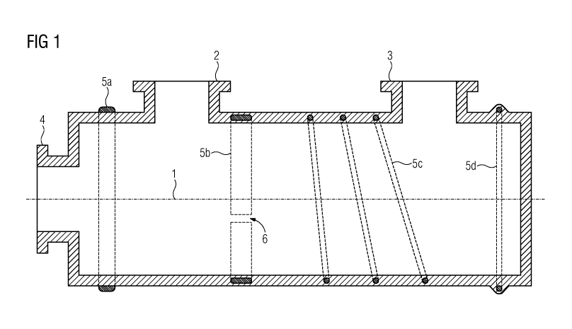
Figure 1 shows an explosion-proof fluid enclosure in a cross
section. The explosion-proof fluid enclosure has a
substantially tubular structure with a cross section in the
form of a circular ring, which is aligned coaxially in relation
to a longitudinal axis 1. The longitudinal axis 1 represents an
axis of symmetry. The explosion-proof fluid enclosure is
provided on the lateral surface with a first and a second
flange 2, 3. Furthermore, a third flange 4 is arranged on a
first end face. The third flange 4 is in this case aligned
coaxially in relation to the longitudinal axis 1, whereas the
first flange 2 and the second flange 3 are aligned
substantially in a radial direction in relation to the
longitudinal axis. On the second end face, facing away from the
first end face, a terminating wall is arranged. For carrying
the flanges 2, 3, 4, a substantially hollow-cylindrical casting
is provided. The explosion-proof fluid enclosure described
above is produced in one piece in a casting process, so that
all the walls and the flanges 2, 3, 4 are cast walls. In the
present case, the cast wall is a metallic cast wall, aluminum
or an aluminum alloy being used as the metal. The explosion-
proof fluid enclosure has in the present case a substantially
tubular structure, aligned coaxially in relation to the
longitudinal axis. The explosion-proof fluid enclosure encloses
an inner volume, which can be filled with an electrically
insulating gas. In order to avoid volatilization of the
electrically insulating gas, the flanges 2, 3, 4 should each be
closed in a fluid-tight manner. The interior of the explosion-
proof fluid enclosure may be additionally provided with
electrical phase conductors, which may have current flowing
through them. The electrical phase conductors are supported on
the explosion-proof fluid enclosure in an electrically
insulated manner. Solid insulators, for example, are used for
this purpose. The electrically insulating gas within the
explosion-proof fluid enclosure may be subjected to an
increased pressure, so
CA 02819282 2013-05-28
PCT/EP2011/069829
2010P24486W0US 10 L
that a compressed-gas insulation is formed inside the
explosion-proof fluid enclosure. In order to establish
electrical contact for phase conductors located within the
explosion-proof fluid enclosure, corresponding pressure-
resistant and fluid-tight insulator lead-throughs may be
arranged at the flanges 2, 3, 4. The insulator lead-throughs
then act together with a phase conductor portion passing
through them to close the flanges 2, 3, 4 of the explosion-
proof fluid enclosure. The explosion-proof fluid enclosure
hermetically seals an enclosed space, which in the present case
is filled with an increased-pressure, electrically insulating
gas and phase conductors kept electrically insulated therein.
In the present case, the explosion-proof fluid enclosure is
designed as a one-piece cast body, reinforcing elements being
positioned on the explosion-proof fluid enclosure for
strengthening.
By way of example, a first reinforcing element 5a is provided
in Figure 1, in the form of a ring on the outer lateral
surface, i.e. outside the space closed off by the explosion-
proof fluid enclosure, resting on an outer surface of the cast
wall. The first reinforcing element 5a acts in the manner of a
bandage which runs continuously around the first longitudinal
axis. A non-magnetic material may be used, for example, as the
material for the first reinforcing element 5a, or an
electrically insulating synthetic or glass fiber may be used.
Furthermore, a second reinforcing element 5b is arranged on the
explosion-proof fluid enclosure. The second reinforcing element
5b is likewise designed in the form of a ring, a break 6 being
arranged within the ring. The break 6 is a slit, which is
passed through by the cast material, here aluminum. As a
result, an inhomogeneity is
CA 02819282 2013-05-28
PCT/EP2011/069829
2010P24486W0US = 11 =
created within the second reinforcement 5b, thereby inhibiting
formation of eddy currents. In the present case, the second
reinforcing element is completely embedded in the cast wall,
i.e. the second reinforcing element is completely encapsulated
by the cast wall. However, it may also be provided that a
reinforcing element is only partially encased by the cast wall,
i.e. only a portion thereof is encased, or portions of the
surface of the second reinforcing element 5b protrude out of
the cast wall.
A third reinforcing element 5c in the present case takes the
form of a helix, the helix running around the longitudinal axis
1. The third reinforcing element 5c may, for example, be
designed in the form of a helically coiled steel wire.
Also represented in Figure 1 is a fourth reinforcing element
5d, which is likewise completely enclosed by the cast wall, the
cast wall comprising a corresponding rib running around in the
form of a ring, which protrudes from the surface contour of the
explosion-proof fluid enclosure and thus additionally brings
about a mechanical strengthening of the cast wall of the
explosion-proof fluid enclosure. In the present case, an
annular structure of the fourth reinforcing element 5d is
provided, the ring being continuous. For example, the ring may
be produced from a non-magnetic material.
Figure 2 shows a plan view of the explosion-proof fluid
enclosure known from Figure 1, an alternative design of
reinforcing elements being represented. It shows a fifth
reinforcing element 5e, which runs in the form of a ring or in
the manner of a loop and may rest on the outer surface of the
explosion-proof fluid enclosure or be at least
CA 02819282 2013-05-28
PCT/EP2011/069829
2010P24486W0US L 12
partially or completely embedded in the cast wall. The fifth
reinforcing element 5e, laid in the form of a loop, is in this
case aligned in such a way that the loop is not passed through
by the longitudinal axis, so that the fifth reinforcing element
5e lies with its loops or its loop in a curved form in/on the
lateral surface, and the explosion-proof fluid enclosure is
stabilized in a shell-like manner. In the present case, in
Figure 2, the fifth reinforcing element 5e is of a two-loop
design, a first loop running around the first and second
flanges 2, 3 and a second loop running only around the first
flange 2.
Figure 3 shows a further design of the explosion-proof fluid
enclosure known from Figures 1 and 2, a sixth and a seventh
reinforcing element 5f, 5g being provided. The sixth and
seventh reinforcing elements each comprise a meshed portion,
the meshed portion having a large number of loops and/or meshes
and/or apertures and/or grids, which are inserted in the
hollow-cylindrical castings of the first and second flanges 2,
3 located on the lateral surface. The meshed portion may in a
general form be referred to as a sheet-like gauze, which is
preferably completely enclosed/embedded in the cast wall. The
meshed portion of the sixth and seventh reinforcing elements
5f, 5g stabilizes the shoulders located at the hollow-
cylindrical castings of the explosion-proof fluid enclosure,
making it more difficult for the first and second flanges 2, 3
and the castings carrying them to be torn off.
Also represented in Figure 3 is an eighth reinforcing element
5h. The eighth reinforcing element 5h is formed in the manner
of a tie rod, the tie rod having a linear extent which is
designed to be substantially parallel to the longitudinal
CA 02819282 2013-05-28
PCT/EP2011/069829
2010P24486W0US L 13 =
axis 1. The eighth reinforcing element 5h braces a cast wall on
the lateral side of the explosion-proof fluid enclosure and
stabilizes the explosion-proof fluid enclosure in the
longitudinal direction.
In the present case, the eighth reinforcing element 5h is
placed on the outer lateral surface. For fixing the eighth
reinforcing oddment 5h, fastening means 7a, b, c, d are
provided at each of its ends, having the effect of bracing the
eighth reinforcing element 5h against an outer surface of the
explosion-proof fluid enclosure. Clamping bolts, screws, rivets
or the like may be provided, for example, as fastening means
7a, b, c, d. However, shoulders which are formed onto the outer
surface and behind which equal and opposite shoulders on the
ends of the eighth reinforcing element 5h are hooked in, while
elastically deforming the eighth reinforcing element 5h, may
also serve as fastening means.
Figure 4 shows a perspective view of the second reinforcing
element 5b known from Figure 1. The second reinforcing element
5b is given the form of a ring, a break being located within
the ring in order to prevent eddy currents from occurring in
the second reinforcing element 5b. Alternatively, it may also
be provided, for example, that non-magnetic materials are used
for forming a continuous ring of a reinforcing element. The
outer surface of the second reinforcing element 5b is provided
with a structure having a large number of notches or
elevations, so that an intimate interconnection between the
created cast wall and the second reinforcing element 5b is
formed when the second reinforcing element 5b is encapsulated
with liquid aluminum. This makes a relative movement of the
reinforcing elements and the cast wall more difficult.
CA 02819282 2013-05-28
,
PCT/EP2011/069829
2010P24486W0US = 14 1
The designs shown in the figures should be understood as merely
given by way of example. In particular, the choice of material,
form, structure, position, etc. may vary. In particular, the
position and shaping of the reinforcing elements 5a, 5b, 5c,
5d, 5e, 5f, 5g, 5h and their position, in or partially in a
cast wall, may be adapted according to the mechanical loads
expected.