Note: Descriptions are shown in the official language in which they were submitted.
CA 02819928 2013-06-04
W02012/083985
PCT/EP2010/007852
1
Process for manufacturing a jointing assembly for medium
or high voltage electrical cables and jointing assembly
obtainable by said process
* * * * *
DESCRIPTION
The present invention relates to a process for
manufacturing a jointing assembly for medium or high
voltage electrical cables.
The invention also relates to a jointing assembly for
medium or high voltage electrical cables obtainable by the
aforementioned process.
In the present description, the term "medium voltage" is
used to refer to a tension typically from about 1 kV to
about 30 kV, while the term "high voltage" refers to a
tension above 30 kV. The term "very high voltage" is used
to define a voltage greater than about 150 kV or 220 kV,
up to 500 kV or more.
In order to make the present description clearer,
reference will be made to a joint, that is a jointing
assembly specifically provided for mechanically and
electrically connecting two electrical cables. However,
the skilled person will understand that analogous
considerations apply when considering a termination, that
is a jointing assembly specifically provided for
mechanically and electrically connecting an electrical
cable to a different device, in those cases where such a
termination comprises features analogous to those
described with respect to the joint. The aforementioned
different device can be for example an electrical power
source, a transformer, a user device etc.
As known, the joints for medium and high voltage
electrical cables typically comprise a radially
CONFIRMATION COPY
SUBSTITUTE SHEET (RULE 26)
CA 02819928 2013-06-04
WO 2012/083985 PCT/EP2010/007852
2
elastomeric sleeve made from a dielectric material and
adapted to be shrunk over a connector connecting the
conductors of two electrical cables and over the end
portions of the insulation layers of such electrical
cables.
In the above-described joints, conductive or semi-
conductive elements are typically provided within the
elastomeric sleeve in correspondence of the connector and
of the end portions of the cable screen, to control the
electric field within the joint, in particular to avoid the
presence of areas with high concentration of electrical
field, wherein undesired electrical discharges and
breakdowns could occur.
EP 0 435 569 discloses a radially shrinkable cylindrical
sleeve for enclosing a connection or a terminal,
respectively, of a medium voltage electrical cable, the
cable including a conductor, an insulation surrounding the
conductor and a shielding layer surrounding Ene
insulation. The sleeve comprises an outer layer made from
a semi-conductive material, a middle layer made of liquid-
silicone rubber and an inner layer which is composed of
two end portions and a median portion which is spaced from
the end portions. Said layers are formed by injection
moulding. The end portions consist of stress controlling
dielectric material. The median portion acts as an
electrode. The end portions and the median portion are
embedded in the insulation material and have preferably
the same wall thickness.
US 4,390,745 discloses an enclosure for electrical
apparatus comprising a first hollow sleeve of insulating
material around which it is positioned a second sleeve
comprising an inner layer of insulating material and an
outer layer of conductive material (normally connected to
the earth, e.g. a cable shield). The first sleeve may have
CA 02819928 2013-06-04
WO 2012/083985 PCT/EP2010/007852
3
an innermost laminated layer of stress grading material.
An embodiment is disclosed wherein a sleeve of
electrically insulating material having an inner lining of
stress gradient material and innermost layers of
electrically conducting material at its central and end
portions is provided.
With specific reference to joints for high voltage
electrical cables, WO 2007/074480 discloses a method of
splicing or joining electric cables together and a related
joint. The joint comprises a covering sleeve in the form
of a tubular sleeve. The sleeve comprises a primary
tubular body including one or more annular inserts of
semi-conductive material, integrated into at least one
layer of insulating material which the reference indicates
as electrode and deflectors (or cups).
The Applicant observed that in a joint of the above-
described type the electrode and the deflectors are
separately made ny moulding. wnen separately moulding
these components, great attention must be paid to the
material and/or design of the respective mould in order to
provide the electrode and the deflectors with the desired
shape, so as to provide an effective electrical field
control within the joint. The separate manufacturing steps
of the electrode and the deflectors make the manufacturing
process of the joint complex and time-consuming.
The Applicant faced the technical problem of reducing the
time and the complexity of the manufacturing of the joint,
and in particular the manufacturing of the electrode and
deflectors, while maintaining the desired ability to
control the electric field in a joint for medium or high
voltage electrical cables.
The Applicant found that this problem can be solved by a
process in which electrode and deflectors of a jointing
assembly are obtained by cutting in portions of suitable
CA 02819928 2013-06-04
WO 2012/083985 PCT/EP2010/007852
4
length a tubular element and by machining the ends of
these portions
Accordingly, in a first aspect thereof, the present
invention relates to a process for manufacturing a jointing
assembly for medium or high voltage electrical cables,
comprising:
- forming a tubular element made from a semi-conductive
material;
- cutting out of said tubular element a first cylindrical
element having a first length and a second cylindrical
element having a second length;
- machining an end portion of said first cylindrical
element and an end portion of said second cylindrical
element to provide them with an at least partially rounded
profile;
- arranging said first cylindrical element at a radially
inner surface of an elastomeric sleeve made from a
Hiplc:tric material and extending about a longitudinal
axis;
- arranging said second cylindrical element at a free end
portion of said elastomeric sleeve, and spaced apart from
said first cylindrical element, with the rounded end
portion of said second cylindrical element facing the
rounded end portion of said first cylindrical element;
- elastically expanding said elastomeric sleeve by
inserting at least one removable support element in a
radially inner position with respect to said elastomeric
sleeve.
In a second aspect thereof, the present invention relates
to a jointing assembly for medium or high voltage
electrical cables, comprising:
- an elastomeric sleeve made from a dielectric material and
extending about a longitudinal axis;
- at least one removable support element coaxially arranged
with respect to said elastomeric sleeve in a radially inner
CA 02819928 2013-06-04
WO 2012/083985 PCT/EP2010/007852
position thereof and adapted to hold said elastomeric
sleeve in a radially expanded state;
- a first cylindrical element arranged at a radially inner
surface of said elastomeric sleeve, said first cylindrical
5 element having a first length and extending about said
longitudinal axis for a portion of said elastomeric sleeve;
- a second cylindrical element arranged at at least one
free end portion of said elastomeric sleeve, said second
cylindrical element having a second length and being spaced
apart from said first cylindrical element;
wherein said first cylindrical element .and said second
cylindrical element have the same outer diameter and
comprise respective end portions facing to each other and
having an at least partially rounded profile obtained by
machining.
Throughout the present description and in the following
claims, the terms "radial" and "axial" (or "longitudinal")
are used to indicate a perpendicular direction and a
parallel direction, respectively, to a reference
longitudinal axis of the jointing assembly, the above
reference longitudinal axis being defined by the
longitudinal axis of the elastomeric sleeve. The expression
"radially inner/outer" is instead used by referring to the
position along a radial direction with respect to the
abovementioned longitudinal axis, while the expression
"axially inner/outer" is used by referring to the position
along a parallel direction to the aforementioned
longitudinal axis and with respect to a plane perpendicular
to said longitudinal axis and intersecting the elastomeric
sleeve in a central portion thereof.
In least one of the aforementioned aspects the present
invention can comprise at least one of the following
preferred features.
Preferably, said at least partially rounded profile is
CA 02819928 2013-06-04
WO 2012/083985 PCT/EP2010/007852
6
obtained by grinding, more preferably by using a shaped
grinding wheel.
Preferably, the process comprises arranging a connector
extending about said longitudinal axis coaxially to said
first cylindrical element in a radially inner position with
respect to said first cylindrical element.
In a preferred embodiment, said first cylindrical element
and said second cylindrical element are defined by
respective inserts incorporated into a radially inner layer
of said dielectric material.
In a particularly preferred embodiment, said tubular
element is manufactured by extrusion. Alternatively said
tubular element can be manufactured by moulding.
Preferably, said tubular element has a constant outer
diameter. More preferably, said tubular element has a
constant thickness.
Preferably, the process of manufacturing a jointing
assembly comprises:
- obtaining from said tubular element two second
cylindrical elements;
- symmetrically arranging said two second cylindrical
elements on opposite side with respect to said first
cylindrical element at two opposite free end portions of
said elastomeric sleeve.
Preferably, the jointing assembly comprises a connector
arranged in a radially inner position with respect to said
first cylindrical element and extending about said
longitudinal axis coaxially to said first cylindrical
element.
Preferably, said first cylindrical element and said at
least one second cylindrical element are obtained from a
single tubular element made from a semi-conductive
CA 02819928 2013-06-04
WO 2012/083985 PCT/EP2010/007852
7
material.
Preferably, said tubular element is manufactured by
extrusion.
In a particularly preferred embodiment, the jointing
assembly comprises two second cylindrical elements, said
two second cylindrical elements being symmetrically
arranged on opposite sides with respect to said first
cylindrical element at two opposite free end portions of
said elastomeric sleeve.
Further features and advantages of the present invention
will appear more clearly from the following detailed
description of some preferred embodiments thereof, such
description being provided merely by way of non-limiting
examples and being made with reference to the annexed
drawings. In such drawings:
- figure 1 is a schematic, partially sectioned, view of
an embodiment of a jointing assembly according to the
present invention in an operative configuration wherein it
mechanically and electrically connects two electrical
cables;
- figure 2 is a schematic enlarged sectional view of a
portion of the jointing assembly of figure 1;
- figure 3 is a schematic enlarged sectional view of a
portion of a tubular element used in the manufacturing
process of the jointing assembly of figure 1.
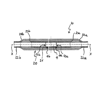
With respect to figure 1, a jointing assembly for medium
or high voltage electrical cables according to the present
invention is indicated with numeral reference 10. In
particular, the jointing assembly of figure 1 is a joint
which is shown in an operative configuration wherein it
mechanically and electrically connects two high voltage
electrical cables 100a, 100b.
CA028199282004
WO 2012/083985 PCT/EP2010/007852
8
Each electrical cable 100a, 100b comprises at least one
conductor 101a, 101b and an insulating layer 102a, 102b
coaxially applied at a radially outer position to the at
least one conductor 101a, 101b. A conductive screen 103a,
103b is coaxially applied at a radially outer position to
the insulating layer 102a, 102b. The conductive screen
103a, 103b is in turn covered with at least one protective
sheath 104a, 104b of electrically insulating plastic or
elastomeric material.
As shown in figure 1, preferably each electrical cable
100a, 100b further comprises at least one semi-conductive
coating 105a, 105b radially interposed between the
insulating layer 102a, 102b and the conductive screen
103a, 103b.
In order to expose the conductors 101a, 101b, the end
portion of each cable 100a, 100b is treated in such a
manner that the conductors 101a, 101b axially project by a
precteterminea amount witn respect to tne respective outer
layers, as clearly shown in figure 1.
As better shown in figure 2, the joint 10 comprises a
connector 11 extending about a longitudinal axis X-X.
The connector 11 is a socket connector, that is it
comprises axially opposite end portions lla, llb each
provided with a seat 12a, 12b adapted to house and lock
into a desired axial position a respective plug-in
connector (not shown) associated with a free end portion
of a respective electrical cable 100a, 100b.
After each of the connectors associated with the end
portions of the electrical cables 100, 100b is inserted
into the respective seat 12a, 12b, this connector is
mechanically coupled to the connector 11 in a conventional
manner, thus providing an electrical connection between
the two electrical cables.
CA 02819928 2013-06-04
WO 2012/083985 PCT/EP2010/007852
9
The connector 11 is made from a metallic material,
preferably tinned aluminium. It comprises two opposite
axially outer surfaces 110a, 110b and a radial tubular
surface 111.
In an alternative embodiment (not shown), the connector 11
is not part of the jointing assembly but it is a separate
element. In this case, before connecting the end portions
of the two cables to the aforementioned connector, the
jointing assembly (with no connector therein) is parked in
a position on one of the two cables. Afterwards, the
jointing assembly is displaced and positioned over the
aforementioned connector and the end portions of the two
cables attached thereto.
As shown in figures 1 and 2, the jointing assembly 10
comprises, in a radially outer position with respect to the
connector 11, an elastomeric sleeve 20. The sleeve 20 can
be made from heat or cold shrinkable dielectric materials.
Preferably, the sleeve 20 is made ot a cold shrinkanie
dielectric material, such as rubber EPDM.
The sleeve 20 extends coaxially to the longitudinal axis X-
X and has a length greater than that of the connector 11.
The connector 11 is centrally arranged within the sleeve 20
along the longitudinal axis X-X so as to have a symmetrical
arrangement of the sleeve 20 about the connector 11 along
the longitudinal axis X-X.
The sleeve 20 comprises, at a radially inner portion
thereof, a first cylindrical insert 21 made from a semi-
conductive material. Throughout the following description,
the insert 21 will be indicated as "electrode".
The electrode 21 extends coaxially to the longitudinal axis
X-X and has a length greater than that of the connector 11
and lower than that of the sleeve 20. The electrode 21 is
symmetrically arranged with respect the connector 11 and
CA 02819928 2013-06-04
WO 2012/083985
PCT/EP2010/007852
the sleeve 20 along the longitudinal axis X-X.
The sleeve 20 further comprises, at each of the end
portions 20a, 20b thereof, a respective second cylindrical
insert 22a, 22b, made from a semi-conductive material.
5 Throughout the following description, the inserts 22a, 22b
will be indicated as "deflectors".
The deflectors 22a, 22b cooperate with the electrode 21 to
control the electrical field within the sleeve 20, in
particular to avoid the presence of areas with high
10 concentration of electrical field, wherein undesired
electrical discharges and breakdowns could occur.
Each of the deflectors 22a, 22b extends coaxially to the
longitudinal axis X-X and axially projects inside the
sleeve 20 toward the electrode 21 so that the radially
inner portion of the sleeve 20 is defined, moving from the
central portion toward each of the end portions 20a, 20b
thereof, by the electrode 21, the dielectric material of
the sleeve 20 and the deflector 22a, 22b.
In the jointing assembly of figure 1 the electrode 21 and
the deflectors 22a, 22b are thus incorporated into the
dielectric material of the sleeve 20.
In an alternative embodiment (not shown) of the jointing
assembly of the present invention, the electrode and the
deflectors are not incorporated into the dielectric
material of the sleeve 20, but are arranged in a radially
inner position with respect to the radially inner surface
of the sleeve 20.
The electrode 21 and at least one of the two deflectors
22a, 22b are both obtained from a single tubular element 25
(figure 3) made from a semi-conductive material.
Preferably, this material is a cold shrinkable semi-
conductive material, more preferably rubber EPDM.
SUBSTITUTE SHEET (RULE 26)
CA 02819928 2013-06-04
WO 2012/083985 PCT/EP2010/007852
11
While it is foreseen an embodiment wherein the
aforementioned tubular element 25 is manufactured by
moulding, it is preferred to manufacture the aforementioned
tubular element by extrusion.
For example, an extrusion by vapour pressure can be carried
out. In this case, a metallic support tube must be arranged
within the extrusion device. Alternatively, an extrusion
using fused salt or micro-wave or gamma rays can be carried
out. In this case no metallic support tube must be arranged
within the extrusion device.
Advantageously, the extrusion manufacturing technique,
specifically when no metallic support tube is required,
allows high productivity and low costs of labour to be
achieved when comparing to a conventional moulding
technique.
Preferably, the tubular element 25 has a constant outer
diameter, so that the electrode 21 and the deflectors 22a,
22b have an identical outer diameter. Preferably, the
tubular element 25 has a constant thickness, so that the
electrode 21 and the deflectors 22a, 22b have identical
outer and inner diameters. Indeed, the Applicant noticed
that such a configuration is particularly adapted to obtain
an effective electrical control field.
Advantageously, once the tubular element 25 is manufactured
it is cut to size in two or more parts, thus obtaining at
least two cylindrical elements of different length which
are adapted to form the electrode 21 and at least one of
the two deflectors 22a, 22b.
In order to properly act as field control means, the
opposite end portions 23a, 23b of the electrode 21 are
shaped so as to provide them with a rounded profile.
Analogously, each of the deflector end portions 24a, 24b
faced to a respective electrode end portion 23a, 23b is
SUBSTITUTE SHEET (RULE 26)
_
W02012/083985 CA 2819928 2017-03-06
PCT/EP2010/007852
12
also shaped so as to provide it with a rounded profile.
With "rounded profile" it is intended a profile having no
sharp edges. Therefore, it is encompassed a totally curved
profile or a profile comprising one or more curved portions
gradually joined to one or more rectilinear portions. The
curved portions can have a single radius of curvatures or
can comprise different portions with different radius of
curvature. Inflexion points may also be present in the
rounded profile.
Preferably, the rounded profile of the end portions 23a,
23b of the electrode 21 is identical to the rounded profile
of the end portions 24a, 24b of the deflectors 22a, 22b
faced thereto, respectively.
The aforementioned rounded profiles are obtained by
machining the end portions of the cylindrical elements
obtained from the aforementioned tubular element 25 by a
proper tool, preferably a properly shaped grinding wheel.
The sleeve 20, together with the electrode 21 and the
deflectors 22a, 22b, is held in a radially expanded state
by support elements (not shown) which are radially
interposed between the connector 11 and the sleeve 20 and
symmetrically arranged along the longitudinal axis X-X with
respect to the connector 11.
The support elements can be in the form of two tubular
elements and are held within the sleeve 20 by a connecting
element which associates the tubular elements with each
other.
After having mechanically and electrically coupled the two
electrical cables to the connector 11, the tubular elements
are axially removed from the opposite end portions 20a, 20b
of the sleeve 20 along opposite directions, thus causing
the sleeve 20, together with
SUBSTITUTE SHEET (RULE 26)
WO 2012/083985 CA 2819928 2017-03-06 PCT/EP2010/007852
13
the electrode 21 and the deflectors 22a, 22b, to shrink
onto the connector 11 and each of the cable end portions
connected thereto. In order to remove the support elements,
the aforementioned connecting element is broken.
In an alternative embodiment (not shown) of the jointing
assembly of the present invention, each support element is
defined by a helically wound strip which is adapted to be
removed from the respective end portion of the sleeve by
pulling a free end portion of the strip.
The jointing assembly 10 of figure 1 further comprises, in
a radially outer position with respect to the sleeve 20, a
first coating shield 40. The shield 40 has a length
substantially equal to that of the sleeve 20.
Preferably, the shield 40 is made of a two-layer sheath
including an radially inner layer and a radially outer
layer.
The radially inner layer is preferably made from a
dielectric material, more preferably rubber EPDM. The
radially outer layer is preferably made from a semi-
conductive material, more preferably rubber EPDM.
Alternatively the shield 40 can be made of a one-layer
sheath, preferably made from a semi-conductive material,
more preferably rubber EPDM.
In a radially outer position with respect to the first
shield 40, a metallic screen 50 is provided. The screen 50
has a length greater than that of the sleeve 20 and is
preferably made of tinned copper.
The jointing assembly 10 further comprises, in a radially
outer position with respect to the screen 50, a second
shield 60 having preferably a length higher than that of
the screen 50.
CA 02819928 2013-06-04
WO 2012/083985
PCT/EP2010/007852
14
Preferably, the shield 60 is made of a two-layer sheath,
that is it includes a radially inner layer made from a
dielectric material and a radially outer layer made from a
semi-conductive material. More preferably, the same
material of the shield 40 is used.
Alternatively the shield 60 can be made of a one-layer
sheath, preferably made from a dielectric material, more
preferably rubber EPDM.
The skilled person will understand that, starting from the
above described different embodiments of the jointing
assembly of the present invention, a plurality of further
different embodiments can be foreseen by combining in
different ways the various features described above. All
these embodiments are indeed encompassed by the present
invention and are within the scope of protection defined by
the attached claims.
While the above description has been made referring to a
jointing assembly for connecting two medium or high
voltage electrical cables, that is a joint, the
description also apply in the case of a jointing assembly
for connecting a medium or high voltage electrical cable
to a different device (such as for example an electrical
power source, a transformer, a user device), that is a
termination, in those cases where such a termination
comprises features analogous to those herewith described
and/or claimed. Therefore, both a joint and a termination
are encompassed by the present invention and are within
the scope of protection defined by the attached claims.
SUBSTITUTE SHEET (RULE 26)