Note: Descriptions are shown in the official language in which they were submitted.
CA 02820449 2013-06-20
- 1 -
ELECTRIC CENTRIFUGAL COMPRESSOR FOR VEHICLES
BACKGROUND OF THE INVENTION
1. Field of the Invention
The present invention relates to an electric centrifugal compressor which is
more specifically adapted to be used in a Heat Ventilation Air Conditioning
(HVAC)
installation for vehicles.
The vehicles may include in particular terrestrial vehicles such as hybrid
electric vehicles (HEV) or electric vehicles (EV) as well as aircrafts or
other kinds
of vehicles.
2. Description of the Related Art
Conventional Electric compressors, such as HVAC compressors for vehicles
are typically associated with an electric motor.
An example of such electric motor driven compressor is given in patent
document US 6 183 215 B1.
Such types of electric motor driven compressors have many drawbacks
linked to lubrication, refrigerants, low operating speed, friction losses and
loss of
compactness.
Two main categories of HVAC electric compressors are used in HEV/EV
vehicles: rotary like vane compressors and oscillating like scroll type
compressors.
Both types of electric compressors which are associated with an electric
motor have the following drawbacks:
- Lubricants are needed for different mechanical parts,
- It is necessary to check compatibility of lubricant oil with refrigerants
(such
as for example the haloalkane refrigerant R134a or the more recently used
CA 02820449 2013-06-20
- 2 -
hydrofluoroolefin refrigerant HF0-1234yf),
- Lubricants should be carefully chosen to protect the electric motor
windings
from the risk of insulation failure,
- An oil separator and leak detection devices are required to avoid
contamination of the electric systems in EV/HEV vehicles,
- The conventional electric compressors have a speed which is limited and
cannot exceed 10,000 rpm,
- Friction losses are detrimental to the operation of the electric
compressor.
SUMMARY OF THE INVENTION
Therefore, it is desired to provide an electric compressor which can solve
most of these problems.
The invention is intended more especially, although not exclusively, to
automotive air conditioning applications and therefore further aims at
providing an
electric compressor which takes into account the high level of vibrations
generated
in a vehicle.
According to an embodiment of the present invention, there is provided an
electric compressor for a heat ventilation air conditioning system for
vehicles, said
electric compressor comprising a motor portion and a centrifugal compressor
portion driven by said motor portion through a shaft, wherein it comprises
electromagnetic means for levitating said shaft during functional operation of
said
electric compressor and auxiliary landing bearings.
According to a preferred embodiment said motor portion comprises an axial
bearingless motor and radial electromagnetic means for levitating said shaft.
The radial electromagnetic means may comprise first and second active
radial magnetic bearings.
According to another embodiment, the radial electromagnetic means
comprise first and second radial bearingless motors.
CA 02820449 2013-06-20
- 3 -
The centrifugal compressor portion may comprise a single wheel, double
wheels, tandem wheels or double tandem wheels.
According to a particular feature, separators are provided between the axial
bearingless motor and the radial electromagnetic means for levitating the iron
shaft.
The axial bearingless motor advantageously comprises a rotor portion
having a plurality of pole pairs armatures and first and second stator
portions
each comprising a core with slots respectively for receiving windings
configured to
impress a motor torque and an axial bearing force, the first and second stator
portions being located on each side of the rotor portion.
Separate windings may be provided in the slots of the first and second
stator portions for respectively impressing a motor torque and an axial
bearing
force.
Alternatively common windings are provided in the slots of the first and
second stator portions for impressing a motor torque and an axial bearing
force.
The axial bearingless motor may comprise a rotor portion chosen among an
induction rotor, a permanent magnet rotor, a hysteresis rotor and a reluctance
rotor.
According to a specific embodiment the centrifugal compressor portion
comprises a wheel at a first end of said shaft and control circuits associated
with
the axial bearingless motor and said radial electromagnetic means are located
at a
second end of said shaft and are connected to said axial bearingless motor and
said radial electromagnetic means via a feedthrough.
The invention further relates to an electric compressor for a vehicle,
wherein said motor portion comprises an electric motor and said
electromagnetic
means for levitating the shaft comprise an active axial magnetic bearing, and
first
and second active radial magnetic bearings located on each side of the
electric
motor.
In such a case if the centrifugal compressor portion comprises at least one
CA 02820449 2013-06-20
- 4 -
wheel at a first end of said shaft, the active axial magnetic bearing may be
located in the vicinity of said centrifugal compressor portion and control
circuits
associated with the electric motor, the active axial magnetic bearing and said
first
and second active radial magnetic bearings may be located at a second end of
said shaft and are connected to said electric motor, said active axial
magnetic
bearing and said first and second active radial magnetic bearings via a
feedthrough.
BRIEF DESCRIPTION OF THE DRAWINGS
Fig. 1 is a schematic longitudinal sectional view of an electric compressor
comprising a compressor portion and a motor portion comprising an electric
motor,
two radial magnetic bearings and a magnetic thrust bearing and further
schematically showing a control device;
Fig. 2 is another schematic longitudinal sectional view of an electric
compressor comprising a compressor portion and a motor portion comprising an
electric motor, two radial magnetic bearings and a magnetic thrust bearing;
Fig. 3 is another schematic longitudinal sectional view of an electric
compressor comprising a compressor portion and a motor portion comprising an
electric motor, two radial magnetic bearings and a magnetic thrust bearing
which
is divided into two parts;
Fig. 4 is a schematic longitudinal sectional view of an electric compressor
comprising a compressor portion (not shown) and a motor portion comprising an
axial bearingless motor and two radial magnetic bearings or two radial
bearingless
motors;
Fig. 5 is a perspective view of an axial bearingless motor (the winding
being not represented);
Fig. 6 is a perspective view of a radial bearingless motor (the winding being
not represented);
CA 02820449 2013-06-20
=
- 5 -
Fig. 7 is a schematic view of an example of compressor portion comprising
double wheels;
Fig. 8 is a schematic view of an example of compressor portion comprising
tandem wheels; and
Fig. 9 is a schematic view of an example of compressor portion comprising
double tandem wheels.
DESCRIPTION OF THE PREFERRED EMBODIMENTS
The present invention will be described in connection with preferred
embodiments which are given by way of examples.
Figure 2 shows an example of a centrifugal electric compressor for heat
ventilation air conditioning (HVAC) which may be dedicated for hybrid electric
vehicles (HEV) or electric vehicles (EV) or else for aircrafts or other types
of
vehicles. Such centrifugal electric compressor may also be applied to boost a
turbocharger.
A rotor shaft 15 of a motor portion 20 is coupled to a centrifugal
compressor wheel 11 of a compressor portion 10 to drive the centrifugal
compressor wheel 11.
An electrical motor 30 comprises a rotor 31 which may be of any type
chosen among induction rotor, permanent magnet rotor, hysteresis rotor and
reluctance rotor. The electrical motor 30 further comprises a stator 32 with
windings 32a.
First and second active radial magnetic bearings 40, 50 are located on each
side of the electrical motor 30 to support the shaft 15 in levitation during
functional operation of the electric compressor. Each active radial magnetic
bearing 40, 50 comprises a rotor 41, 51 fast with the shaft 15 and a stator
42, 52
with windings 42a, 52a.
An active axial magnetic bearing 60 (thrust bearing) comprises on the one
CA 02820449 2013-06-20
- 6 -
hand a disc 61 which is mounted perpendicular to the axis of the shaft 15 and
constitutes a rotor armature and on the other hand first and second stators
62, 63
each having at least one annular coil or winding 62a, 63a located in a stator
62,
63 which may have a C-shaped core, as shown in figure 2. Alternatively each
stator 62, 63 could have an E-shaped core with two coils.
The radial bearing rotors 41, 51 are equipped with ferromagnetic
laminations which are held in position by the magnetic fields created by the
electromagnets of the stators 42, 52.
The shaft 15 is levitated in a contactless manner due to the radial magnetic
bearings. The shaft's position is monitored by sensors (not shown), e.g. of
the
variable inductive type, which detect any deviation from nominal position and
emit
signals which are used in a control system (not shown in figure 2) to command
currents in the windings 42a, 52a of the radial bearings in order to bring the
shaft
back to its nominal position. The axial bearing 60 is based on the same
15 principle and sensors (not shown) send signals to a controller to adjust
command
currents in the coils 62a, 63a of the axial bearing 60 to adjust the axial
position of
the shaft 15.
Auxiliary landing bearings 8 are used for supporting the shaft 15 essentially
during a starting or stopping operation of the motor portion 20, but also
during
brief intermittent periods in case of shock-loads due to the usually high
level of
vibrations present in a vehicle.
Generally speaking where a rotary shaft is suspended by means of an
active magnetic suspension servo-controlled on the basis of sensors for
detecting
the position of the rotary shaft, auxiliary bearings, also known as emergency
bearings, are provided in order to support the shaft while the machine is
being
stopped or in the event of a total or partial failure of the magnetic
suspension,
thereby preventing direct contact between the magnetic circuits of the rotors
and
the stators of the magnetic bearings or bearingless motors when the windings
of
the stator electromagnets are not properly powered, thus avoiding damage to
the
CA 02820449 2013-06-20
- 7 -
laminations thereof. In normal operation, auxiliary bearings leave clearance
about
the rotary shaft and do not themselves rotate. The clearance provided for the
auxiliary bearings is generally about one half the width of the air gap of the
magnetic bearings or bearingless motors.
The auxiliary landing/touch down bearings 8 may have a variety of designs
and may be for example rolling bearings, needle bearings, plain bearings,
bushings, etc...
Separators 9 may be located between the stator windings of the magnetic
bearings 40, 50, 60 and of the electrical motor 30.
The casing or flanges and cooling systems with a refrigerant are
conventional and are not represented in the drawings.
In figure 2 the axial bearing 60 comprises a disc armature 61 and two
stators 62, 63 located at an end of the shaft 15, whereas the compressor wheel
is
located at the other end of the shaft. However, as shown in figure 1, the
axial
bearing 60 can also be located on the same side than the compressor wheel 11.
As shown in figure 1, control circuits 70 comprising a variable frequency
drive 71 and amplifiers 72 associated with the electrical motor 30 and the
radial
electromagnetic bearings 40, 50, 60 are integrated in a flange and located at
a
second end of the iron shaft 15. The control circuits 70 are connected to the
electrical motor 30 and to the radial and axial electromagnetic bearings via a
feedthrough 74. A connector 73 serves to connect the control circuits 70 to a
further controller located remote from the electric compressor.
Figure 3 shows an embodiment which is similar to the embodiment of
figure 2, but the axial magnetic bearing is split into two parts 60A, 60B
which are
located at both ends of the shaft 15. A disc armature 61A integral with the
shaft
15 is located at a first end of the shaft 15 near the compressor wheel 11 and
cooperates with a first stator 62 having a first coil 62a which could be
similar to
the stator 62 of figure 1. A disc armature 61B integral with the shaft 15 is
located
at a second end of the shaft 15 and cooperates with a second stator 63 having
a
CA 02820449 2013-06-20
,
- 8 -
second coil 63a which could be similar to the stator 63 of figure 1.
Figures 1 to 3 show a compressor portion 10 having a single wheel.
However other designs of the compressor portion 10 may be used in combination
with the different embodiments disclosed herein.
Thus as shown in figure 7, a compressor portion 10 may include double
wheels 11, 13. As shown in figure 8, a compressor portion 10A, 10B may include
tandem wheels 11, 12. As shown in figure 9, a compressor portion 10A, 10B may
include double tandem wheels 11, 13, 12, 14. The configurations of compressor
wheels according to figures 7 to 9 are intended either to increase the
pressure
ratio or to increase the flow.
Preferred embodiments of the invention will now be described in connection
with figures 4 to 6.
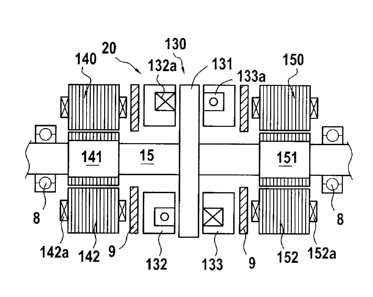
Figure 4 shows an embodiment with an iron shaft 15 and a motor portion
which are more compact than the embodiments of figures 1 to 3 since the
15 electrical motor 30 and the axial bearing 60 or 60A, 60B are replaced by
a single
axial bearingless motor 130. In figure 4, the compressor portion 10 has been
omitted but may be realized as previously described with reference to figures
1 to
3 and 7 to 9.
The embodiment of figure 4 allows reducing the shaft length and hence
20 improves the overall layout.
The axial bearingless motor 130 comprises a disc-like central armature 131
integral with the shaft 15 and first and second stators 132 and 133 with
windings
132a, 133a.
Figure 5 shows in perspective an example of a possible configuration of an
axial bearingless motor 130. The axial bearingless motor 130 of figure 5
comprises a rotor portion 131 having a plurality of pole pairs armatures 138
and
first and second stator portions 132, 133 each comprising a core with slots
134,
135 respectively for receiving windings (not shown in figure 5) configured to
impress a motor torque and an axial bearing force, the first and second stator
CA 02820449 2013-06-20
- 9 -
portions 132, 133 being located on each side of the rotor portion 131.
In the stator portions 132, 133 of the axial bearingless motor separated
coils may be used to impress the bearing force and the motor torque.
Alternatively the needed bearing force and motor torque may be generated
in each coil by combined windings. In such a case a single coil will carry
jointly the
required motor and bearing ampere-turns.
A plurality of pole pairs armatures 138 are shown in figure 5 by way of
example. However the rotor 131 may carry different structural elements
depending on the chosen principle (permanent magnet, induction, switched
reluctance, hysteresis).
As a non limiting example, the stator 132 and the rotor 131 with
permanent magnets 138 may constitute a permanent magnet motor, where the
permanent magnets 138 on the rotor surface produce an axial force in a first
direction (upward direction in the configuration of figure 5), whereas the
stator
133 and rotor 131 may constitute a synchronous reluctance motor, where the
winding currents of the synchronous reluctance motor produce an adjustable
axial
force in the opposite direction with respect to the first direction (downward
direction in the configuration of figure 5). The axial position of the rotor
can thus
be controlled by the currents of the synchronous motor. However as mentioned
above other combinations of motor types may be chosen as soon as the axial
bearingless motor 130 achieves the two functions of impressing a motor torque
and an axial bearing force.
Active radial magnetic bearings 140 and 150 similar to previously described
active radial magnetic bearings 40 and 50 and comprising a rotor armature 141,
151 and a stator 142, 152 with windings 142a, 152a may be located on each side
of the axial bearingless motor 130.
However according to another embodiment each active radial magnetic
bearing 140, 150 may be replaced by a radial bearingless motor 180.
An example of radial bearingless motor 180 is represented in figure 6. Such
CA 02820449 2013-06-20
- 10 -
radial bearingless motor 180 comprises a rotor 181 integral with the shaft 15
and
a stator 182 with slots 184 for receiving coils 185. The rotor 181 carries
different
structural elements 183 depending on the chosen principle (permanent magnet,
induction, switched reluctance, hysteresis).
Basically the stator windings 185 achieve both functions of torque windings
and suspension force windings. As an example if two magnetic fields, which may
be created by two winding sets with a difference in the pole pair number of
one,
are superposed, a torque and a radial force will be produced. It is thus
possible
for example to combine a 4-pole motor winding of a reluctance motor with a 2-
pole bearing winding, but many other embodiments are possible.
Patent document US 6727618 B1 discloses an example of bearingless
switched reluctance motor.
Although preferred embodiments have been shown and described, it
should be understood that any changes and modifications may be made
therein without departing from the scope of the invention as defined in the
appended claims.
In figure 4 reference numeral 130 designates an axial bearingless motor
located between two radial electromagnetic means 140, 150 for supporting the
shaft 15. If the radial electromagnetic means 140, 150 comprise first and
second radial bearingless motors 180 such as disclosed for example in figure
6,
an axial active magnetic bearing such as the thrust bearing 60 illustrated in
figure 2 could be substituted for the axial bearingless motor 130.