Note: Descriptions are shown in the official language in which they were submitted.
CA 02820478 2013-06-06
WO 2011/071942 PCT/US2010/059325
TITLE
REMOTE FIRE DETECTION BYPASS FOR TESTING
FIRE/SMOKE ALARM AND INDICATION DEVICES
INVENTOR
SALVADOR SEBASCO
Citizenship: USA
(Escondido, California)
CROSS-REFERENCE TO RELATED APPLICATIONS
[0001] This application claims the benefit of priority to prior-filed
United States
Provisional patent application Serial No. 61267391, filed December 7, 2009,
the complete
contents of which is hereby incorporated herein by reference.
BACKGROUND
Field of the Invention
[0002] The present disclosure relates generally to the field of fire
safety and fire
warning devices and more specifically to a remote fie equipment testing system
to test
emergency fire equipment and systems through the use of a hand-held device.
Background
[0003] To ensure the safety of residential, commercial and industrial
buildings and
their occupants in the event of a fire, all buildings must be equipped with
fire safety
equipment and systems. Fire alarm and indication devices and systems are
complex and
require many parts to work properly in unison to successfully warn of the
serious danger a
fire presents. For fire safety equipment and systems to be maintained in a
condition so as to
be reliable in the event of a fire they must be regularly tested to ensure
their ability to perform
as designed in the event of a fire.
1
CA 02820478 2013-06-06
WO 2011/071942 PCT/US2010/059325
[0004] Fire safety equipment and systems include various smoke detectors
and
alarms, fire alarm systems, emergency exit signs, various automatic emergency
lighting, etc.
The manufacturers of such equipment and systems strongly recommend these
devices and
systems be tested weekly or monthly. Furthermore, fire safety equipment and
systems in
commercial and industrial buildings are required by law to be tested on a
weekly or monthly
basis depending on the specific equipment and system.
[0005] Such testing is often cumbersome because fire safety equipment and
systems
are often located in inconvenient and out-of-reach places (usually on ceilings
or at the top of
walls) and require a button be pressed on the device in order to conduct a
test of the device
performance. The often arduous effort required in reaching fire/smoke alarms
and indication
equipment to test their performance prevents many fire/smoke alarms and fire
safety systems
from being properly tested. Especially in residential homes where one or two
adults may be
responsible for testing multiple alarms on a monthly basis which all require a
ladder to
access, such testing can easily be ignored and forgotten as requiring too much
time and effort.
[0006] The current method of fire safety equipment and system testing,
which most
often requires a button be pressed on a device located on a ceiling or at the
top of a wall,
leads such equipment to not be tested as often as is proper. Buildings
equipped with fire
safety equipment and systems that are not tested as often as recommended by
the
manufacturer present a danger to people located within such buildings that the
building may
catch on fire and those within the building will not be warned of the fire in
time to exit the
building safely.
[0007] What is needed is a device that can initiate the test for fire
safety equipment
from a location remote from that of the fire safety equipment itself. It is
desired that the
device bypass the fire/smoke detection circuitry and test the fire
alarm/indication function of
the fire safety equipment.
2
CA 02820478 2013-06-06
WO 2011/071942 PCT/US2010/059325
BRIEF DESCRIPTION OF THE DRAWINGS
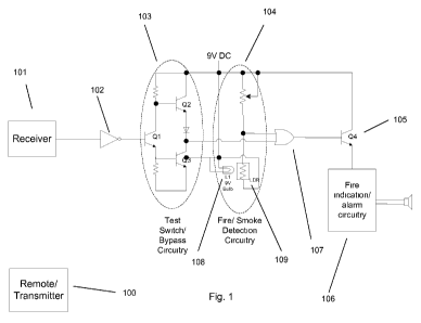
[0008] Fig. 1 depicts a schematic of an embodiment of the present device
(test switch/
bypass circuitry) wired to bypass a smoke detection circuit to activate a test
of the fire
indication/alarm circuitry.
[0009] Fig. 2 depicts an embodiment of the transmitter that comprises a
battery
indicator light, a light and/ or speaker to indicate signal transmission, and
a button that when
pressed sends a signal to the receiver that will test the fire indication/
alarm circuitry.
[0010] Fig. 3 depicts a flow chart depicting the operation of the system
depicted in
Figs. 1 and 2.
3
CA 02820478 2013-06-06
WO 2011/071942 PCT/US2010/059325
DETAILED DESCRIPTION
[0011] Fig. 1 depicts an embodiment of the present device wired as a
bypass to the
detection circuitry 104 of a smoke detector. The present device can be wired
as a bypass to
the detection circuitry to any fire safety equipment to allow the fire
indication/ alarm circuitry
of such equipment to be tested without requiring the fire safety device be
manually activated
and without the detection of an actual fire or smoke to trigger the
indication/ alarm circuitry.
[0012] The device is comprised of two parts: one part can be a remote
transmitter 100
which can be located in a conveniently accessible place to the user and the
second part is
comprised of a receiver 101 and bypass circuitry 102 and 103 which can be
connected
directly to the fire safety device. To test the fire safety equipment 106 the
user can press a
button 203 on the remote transmitter 100 which can send a signal to the
receiver 101. In
some embodiments, the signal sent from the remote transmitter 100 to the
receiver 101 can be
wireless, but in other embodiments can be sent via an electrical, optical, or
any other known
and/or convenient conduit. If a wireless embodiment is employed, the power of
the signal
sent from the remote transmitter 100 can be such that the range for successful
transmission
can require the transmitter be within approximately 10m of the receiver 101
when the button
is pressed in order to prevent inadvertent activations of the fire indication/
alarm circuitry
and/ or to allow the device to consume minimal power.
[0013] In some embodiments the remote transmitter 100 can contain a
battery
indicator light 200 or other convenient indicator of the transmitter's battery
power to signify
to the user that that battery power of the transmitter is sufficient to send
the desired signal to
the receiver. The transmitter can also contain one or a plurality of indicator
light(s) 201 and/
or a speaker 202 to indicate either by light or by sound that the transmitter
successfully sent
the signal and/ or if the receiver 101 received that signal.
4
CA 02820478 2013-06-06
WO 2011/071942 PCT/US2010/059325
[0014] In some embodiments when the button 203 on the transmitter 100 is
pressed
and the transmitter 100 is within the prescribed distance from the receiver
101, the receiver
101 can detect the signal from the transmitter 100 and can output a high
signal which can be
made low by the inverter 102. That low signal input to the switch 103 can
output a high
signal to the 'or' gate 107 which can put a high signal on the base of
junction 105, switching
junction 105 from cutoff to saturation, allowing current to flow to the fire
alarm circuitry, as
if a fire had been detected; thus testing the fire indication/alarm circuitry
106.
[0015] In some embodiments, when the signal received by the receiver 101
is other
than above a prescribed value, the receiver 101 can output a low signal which
can be made
high by the inverter 102. The high signal input to the switch 103 can output a
low signal to
the 'or' gate 107. If the fire/smoke detection circuitry 104 detects fire or
smoke (for example,
in Fig. 1 the light emitted by indicator 108 is blocked before reaching the
variable resistor
109, causing the variable resistor 109 to increase resistance) a high signal
can be sent to the
'or' gate 107 which can put a high signal on the base of junction 105,
switching junction 105
from cutoff to saturation, allowing current to flow to the fire alarm
circuitry 106.
[0016] If neither the test switch/ bypass circuitry 103 nor the
fire/smoke detection
circuitry 104 are activated they will both send low signals to the 'or' gate
107 which can
output a low signal to junction 105, keeping junction 105 in a cutoff state
and preventing
current from flowing to the fire indication/alarm circuitry 106. Thus, the
fire indication/
alarm circuitry 106 will remain 'off' until fire/smoke is detected unless the
button 203 on the
transmitter 100 is pressed and a signal is successfully sent from the
transmitter 100 and
received by the receiver 101.
[0017] The circuitry configuration in figure 1 as well as the test
switch/ bypass
circuitry 103 provided in figure 1 and referred to above can be accomplished
through
CA 02820478 2013-06-06
WO 2011/071942 PCT/US2010/059325
numerous alternative means through various electrical systems and can provide
a function
equal to that of the circuitry shown in figure 1.
[0018] The circuitry of the fire/ smoke detection circuitry 104 in figure
1 can vary
with different fire safety equipment and systems. Test switch/ bypass
circuitry 103 can be
adapted to successfully bypass various fire safety equipment and systems to
allow a remote
transmitter 100 to activate and test the fire indication/ alarm circuitry.
[0019] Fig. 3 depicts a flow chart depicting the operation of the system
depicted in
Figs. 1 and 2. In the embodiment depicted in Fig. 3, the system 300 can
operate in a normal
detection mode 302. In the normal detection mode, the detection system can
perform the
normal functions of detecting an event, such as excess smoke for a smoke
detector or excess
carbon monoxide for a carbon monoxide detector and/or any other known and/or
convenient
detection function. In step 302, the system 300 can test for and/or detect a
bypass/test signal,
such as can be transmitted by the device depicted in Fig. 2. If the system 300
detects a
bypass/test signal, an alarm can be triggered. In some embodiments the alarm
can be visual
and/or audible. However, in alternate embodiments any known and/or convenient
alarm
signal can be emitted by the system in response to the bypass/test signal. If
the system 300
does not detect a bypass/test signal, the system 300 can return to a normal
operation state
302. In some embodiments the cycle of the detection to normal state can be
less than 1 ms.
However, in alternate embodiments the cycle of the system 300 can have any
known and/or
convenient duration. In still further alternate embodiments a cycle
frequency/period may not
be present.
[0020] Although the invention has been described in conjunction with
specific
embodiments thereof, it is evident that many alternatives, modifications and
variations will be
apparent to those skilled in the art. Accordingly, the invention as described
and hereinafter
6
CA 02820478 2013-06-06
WO 2011/071942
PCT/US2010/059325
claimed is intended to embrace all such alternatives, modifications and
variations that fall
within the spirit and broad scope of the appended claims.
7