Note: Descriptions are shown in the official language in which they were submitted.
SPIRALLY WOUND MICROBIAL FUEL CELL
FIELD OF THE INVENTION
The present invention relates generally to bioelectric chemical devices
and more particularly to bacterial fuel cells.
BACKGROUND OF THE INVENTION
The following publications are believed to represent the current state of
the art:
Microbial Fuel Cells: Methodology and Technology, Bruce E. Logan et
al, Environ. Sci. Technol., 40 (17), 5181 - 5192, 2006;
Microbial Fuel Cells¨Challenges and Applications, Bruce E. Logan &
John M. Regan, Environ. Sci. Tech., 40 (17), 5172 - 5180, 2006;
Stefano Freguia, Komeel Rabaey, Zhiguo Yuan, Jurg Keller, Non-
catalyzed cathodic oxygen reduction at graphite granules in microbial fuel
cells,
Electrochimica Acta, 53, 598-603, 2007;
Hong Liu et al., Quantification of the internal resistance distribution of
microbial fuel cells, Environ. Sci. Technol., 42 (21), 8101 ¨ 8107, 2008;
US published patent application no. 20070259217; and
PCT published patent application no. WO 2010/049936.
1
CA 2820663 2017-10-05
CA 02820663 2013-05-23
WO 2012/081001
PCT/1L2010/001051
SUMMARY OF THE INVENTION
The present invention seeks to provide an improved bacterial fuel cell for
use in wastewater treatment.
There is thus provided in accordance with a preferred embodiment of the
present invention a bacterial fuel cell including at least one anode and at
least two
cathodes in liquid communication with a liquid to be treated, the at least one
anode
being separated from the at least two cathodes by at least first and second
electrically
insulating spacers and the at least one anode and the at least two cathodes
being
electrically connected across an external load and the at least one anode and
the at least
two cathodes being wound together generally in a spiral configuration together
with at
least a third electrically insulating spacer.
In accordance with a preferred embodiment of the present invention, the
at least one anode and the at least two cathodes are formed of a flexible
material.
Preferably, sealing is provided between the at least two cathodes,
whereby the at least one anode is enclosed inside an enclosure including the
sealing and
the at least two cathodes.
Preferably, the electrically insulating spacers include plastic nets.
Preferably, the at least two cathodes are oxygen permeable.
Preferably, a multiplicity of electrical output connections is distributed
along a length of the spiral.
In accordance with a further preferred embodiment of the present
invention, the at least one anode and the at least two cathodes- each include
a metal
electrical conductor and an electrically conductive coating at least between
the metal
electrical conductor and the liquid to be treated, the electrically conductive
coating
being operative to mutually seal the liquid and the electrical conductor from
each other.
Preferably, the metal electrical conductor includes a coated metal
electrical conductor and the electrically conductive coating includes an
electrically
conductive coating formed onto the metal electrical conductor.
Preferably, the coated metal electrical conductor of at least one of the at
least two cathodes is water permeable.
2
CA 02820663 2013-05-23
WO 2012/081001
PCT/1L2010/001051
Preferably, the bacterial fuel cell also includes at least one conductive
surface adapted for biofilm growth on a surface thereof, which conductive
surface is in
liquid communication with the liquid to be treated and is in electrical
communication
with the metal electrical conductor via the electrically conductive coating.
Preferably, the electrically conductive coating is adapted for biofilm
growth on a surface thereof and the at least one conductive surface adapted
for biofilm
growth is defined by a fabric overlying a surface of the electrically
conductive coating.
Additionally or alternatively, the at least one surface adapted for biofilm
growth is defmed by a conductive fabric, wherein the metal electrical
conductor
includes a coated metal electrical conductor and the electrically conductive
coating
includes an electrically conductive coating formed on the metal electrical
conductor.
Preferably, the conductive fabric includes carbon.
In accordance with another preferred embodiment of the present
invention, the at least two cathodes each also includes an oxygen permeable,
liquid-
impermeable layer adjacent the electrically conductive coating and the oxygen
permeable, liquid-impermeable layer is exposed to an oxygen-containing gas.
Preferably, the oxygen permeable, liquid-impermeable layer includes
silicone rubber or includes a micro-perforated film including a poly olefin
such as
polyethylene or polypropylene.
In accordance with yet another preferred embodiment of the present
invention, the metal electrical conductor includes a perforated planar
element.
Preferably, at least one of the at least two cathodes includes an
attachment layer and the attachment layer preferably includes a plastic
fabric.
Preferably, the electrically conductive coating includes a conductive
plastic.
Preferably, the metal electrical conductor includes copper or aluminum.
In accordance with a preferred embodiment of the present invention, a
wastewater treatment installation includes a plurality of bacterial fuel cells
and the
plurality bacterial fuel cells is arranged in a stacked configuration.
Preferably, the plurality of bacterial fuel cells is hydraulically connected
in series. Additionally or alternatively, the plurality of bacterial fuel
cells is
hydraulically connected in parallel.
3
CA 02820663 2013-05-23
WO 2012/081001
PCT/1L2010/001051
Additionally or alternatively, the plurality of bacterial fuel cells is
electrically interconnected.
=
4
CA 02820663 2013-05-23
WO 2012/081001
PCT/1L2010/001051
BRIEF DESCRIPTION OF THE DRAWINGS
The present invention will be understood and appreciated more fully
from the following detailed description, taken in conjunction with the
drawings in
which:
Figs. 1A and 1B are simplified respective illustrations of a bacterial fuel
cell and an enlarged portion thereof, constructed and operative in accordance
with a
preferred embodiment of the present invention;
Figs. 2A and 2B are simplified expanded illustrations of two alternative
embodiments of an anode useful in a bacterial fuel cell of the type
illustrated in Figs. I A
and 1B, constructed and operative in accordance with a preferred embodiment of
the
present invention;
Fig. 3 is a simplified expanded illustration of a cathode useful in a
bacterial fuel cell of the type illustrated in Figs. 1A and 1B, constructed
and operative in
accordance with a preferred embodiment of the present invention; and
Fig. 4 is a simplified illustration of a wastewater treatment installation
employing multiple ones of bacterial fuel cells of the type illustrated in
Figs. 1 ¨ 3,
constructed and operative in accordance with a preferred embodiment of the
present
invention.
CA 02820663 2013-05-23
WO 2012/081001
PCT/1L2010/001051
DETAILED DESCRIPTION OF PREFERRED EMBODIMENTS
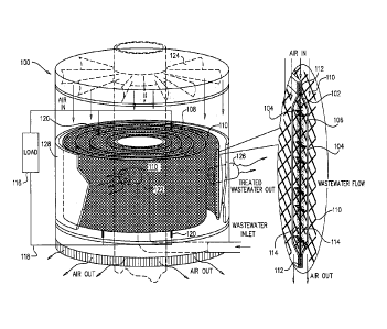
Reference is now made to Figs. IA and 1B, which are simplified
respective illustrations of a bacterial fuel cell and an enlarged portion
thereof,
constructed and operative in accordance with a preferred embodiment of the
present
invention.
As seen in Figs. IA and 1B, there is provided a bacterial fuel cell 100
including an anode 102 flanked by first and second cathodes 104, each in
liquid
communication with a liquid to be treated, such as industrial or municipal
wastewater
106. Anode 102 and cathodes 104 are preferably formed of a flexible material
and are
preferably wound together in a generally spiral configuration 108, together
with an
electrically insulative spacer 110. The thickness of electrically insulative
spacer 110
defines a separation between adjacent layers of the spiral 108 thereby
allowing air to
flow therebetween and hence electrically insulative spacer 110 may also be
termed an
air-side spacer 110. It is appreciated that the gap shown in Fig. 1A between
air-side
spacer 110 and adjacent layers of the spiral 108 is shown for purposes of
clarity of
presentation only, since in fact air-side spacer 110 preferably constitutes
the entire
separation between adjacent layers of spiral 108 and no additional spacing is
present.
Cathodes 104 preferably enclose anode 102 by means of a plastic
welding 112 preferably provided at top and bottom edges of cathodes 104, which
plastic
welding 112 serves both to seal and to mutually isolate the anode and cathodes
102 and
104. Anode 102 is preferably spaced apart from cathodes 104 by means of at
least two
electrically insulative spacers 114. Electrically insulative spacers 114
define a
separation between the anode 102 and cathodes 104 thereby allow wastewater 106
to
flow between the central anode 102 and the cathodes 104 on either side of it.
Hence,
electrically insulative spacers 114 may also be termed water-side spacers 114.
Air-side spacer 110 and water-side spacers 114 each preferably comprise
flexible highly perforated nets, the thicknesses of which are determined
according to the
system's hydraulic requirements. Specifically, the use of relatively thinner
spacers 110
and 114 provides increased active surface area per unit volume, thereby
allowing the
system to be more compact, whereas the use of relatively thicker water-side
spacers 114
6
CA 02820663 2013-05-23
WO 2012/081001
PCT/1L2010/001051
leads to reduced clogging along the wastewater flow path. Given these
considerations, it
is generally preferable to include spacers 110 and 114 having thicknesses in
the range of
4 - 15 mm which provide a sufficiently high surface area and sufficiently low
susceptibility to clogging, following conventional pre-treatment screening
processes of
the wastewater 106.
Anode 102 and cathodes 104 are preferably electrically connected across
an external load 116 via an electrical circuit 118. A multiplicity of
electrical output
connections 120 is preferably distributed along a length of the spiral 108.
Electrical
output connections 120 preferably provide for current discharge, whereby
resistances
and hence ohmic losses are minimized.
It is appreciated that although in the embodiment illustrated in Figs. 1A
and 1B only a single anode and two cathodes are shown, the inclusion of more
anodes
and/or cathodes is also possible. Additional sets of one anode and two
cathodes may be
included in the embodiment illustrated in Figs. 1 A and 1B by means of
connecting
multiple ones of spiral 108 in series or in parallel and/or by using a spiral
having
multiple layers of anodes and cathodes.
Spiral 108, including anode 102, cathodes 104 and intervening water-side
spacers 114, may be manufactured by roll-to-roll processing methods, which
methods
are well known in the art. Following manufacture the spiral 108 may be rolled
together
with air-side spacer 110, the thickness of which, as described above, defines
the
separation between adjacent turns of the spiral 108.
The production of anode 102, cathodes 104, air-side spacer 110 and
water-side spacers 114 in the form of continuous rolls rather than as
pluralities of
discrete components significantly reduces production costs and increases
production
efficiency. Furthermore, maintenance and quality control of the spiral 108 is
simplified,
since the spiral may simply be unrolled as required in order to correct any
deficiencies
that may arise during the course of operation.
In operation of bacterial fuel cell 100, wastewater 106 enters the cell at
an inner end of the spiral 108 via an inlet port 122 and is preferably evenly
distributed
by means of a flow distribution element. Water-side spacers 114 serve to
maintain an
even distribution of wastewater and to sustain sufficient turbulence. Air
preferably
enters the top of bacterial fuel cell 100 and flows downwards through the
cell. Air is
7
CA 02820663 2013-05-23
WO 2012/081001
PCT/1L2010/001051
preferably evenly distributed across the spiral 108 by means of a fan 124 or
similar
ventilation apparatus that may be installed in the vicinity of bacterial fuel
cell 100 and
air-side spacer 110 serves to maintain an even distribution of air and to
sustain sufficient
turbulence. Wastewater 106 is biologically treated as it flows through
bacterial fuel cell
100 so as to decrease its concentration of organic matter, as will be
explained in greater
detail below. Treated wastewater exits at an outer end of the spiral 108 via
an outlet port
126 and outgoing air is preferably freely discharged to the atmosphere.
Bacterial fuel
cell 100 is preferably enclosed within a cylindrical enclosure 128.
It is appreciated that the direction of wastewater flow described above
may also be reversed, with wastewater 106 entering the bacterial fuel cell 100
at an
outer end of spiral 108 and treated wastewater exiting at an inner end of
spiral 108.
As seen most clearly in Fig. 1B, anode 102 and cathodes 104 each
preferably comprises a multilayered structure, including a metal electrical
conductor
surrounded by an electrically conductive coating. The construction of anode
102 is best
understood with reference to enlargement 130 in Fig. 1B. It is seen that a
metal
conductor 132, preferably formed of copper or aluminum, is surrounded by an
electrically conductive coating 134. The electrically conductive coating 134
is
preferably formed by laminating a pair of liquid impermeable conductive
plastic sheets
so as to encase the metal conductor 132 or by co-extruding the metal conductor
with a
conductive plastic to form a round or flat cable. Preferably, the conductive
plastic
coating is formed of a plastic such as polyethylene, polypropylene or EVA or a
combination thereof, which is compounded with a conductive powder, such as a
carbon
and/or graphite powder, so as to produce a conductive compound processed to
coat the
metal. =
Biofilm growth is preferably supported on the outer surfaces of
electrically conductive coating 134. Optionally a biofilm growth support 136
is
provided on at least one outer surface of electrically conductive coating 134.
Biofilm
growth support 136 is preferably formed of a non-woven plastic or carbon
fabric and
preferably also functions as an attachment layer.
Typical thicknesses of the various elements of anode 102 are as follows:
Metal conductor 132 20 - 200 microns;
conductive coating 134 50 - 400 microns; and
8
CA 02820663 2013-05-23
WO 2012/081001
PCT/1L2010/001051
biofilm growth support 136 10 - 50 microns.
Reference is additionally made to Figs. 2A and 2B, which illustrate two
alternative embodiments of anode 102. In the embodiment of Fig. 2A, the
conductor
132 is preferably in the form of a perforated planar element and is designated
by an
additional reference numeral 138 and the electrically conductive coating 134
is
preferably in the form of a sheet or film of conductive plastic. In the
embodiment of Fig.
2B, the conductor 132 is preferably in the form of a perforated planar metal
element
140, all of whose surfaces are coated by a liquid-impermeable electrically
conductive
coating 142, as seen at enlargement 144. Carbon-based fabric coating 134 is
preferably
attached to conductor 132 on either side thereof. Attachment and biofilm
growth support
layer 136 is preferably made of a non-woven plastic.
The construction of cathodes 104 is best understood with reference to
enlargement 150 in Fig. 1B. It is appreciated that although enlargement 150 is
shown to=
emanate from the left hand side cathode 104, the structure shown therein is
equally
applicable to the right hand side cathode 104. It is seen that a perforated
metal
conductor 152, preferably formed of copper or aluminum, is surrounded by an
electrically conductive coating, which electrically conductive coating is
preferably
realized by coating the metal conductor 152 with a liquid-impermeable
electrically
conductive plastic and encasing the coated metal conductor on a liquid facing
side
thereof with an electrically conductive layer 154. Electrically conductive
layer 154 is
preferably formed of an electrically conductive perforated plastic, produced
by
compounding a plastic such as polyethylene, polypropylene or EVA or a
combination
thereof with a conductive powder, such as a carbon and/or graphite powder.
Alternatively, the electrically conductive layer 154 may be formed of a carbon-
based
fabric.
Biofilm growth is preferably supported on outer surfaces of coated metal
conductor 152 and electrically conductive layer 154. Optionally, an attachment
layer
and biofilm growth support 156 is provided on at least one outer surface of
electrically
conductive layer 154. Attachment layer and biofilm growth support 156 is
preferably
formed of a non-woven plastic fabric.
On an opposite, air-facing side of coated metal conductor 152 there is
preferably provided a liquid-impermeable, oxygen-permeable layer 158,
preferably
9
CA 02820663 2013-05-23
WO 2012/081001
PCT/1L2010/001051
formed of silicone rubber or a micro-perforated polyolefin, such as
polypropylene or
polyethylene. Outwardly of liquid-impermeable, oxygen-permeable layer 158
there is
optionally provided an attachment layer 160 typically comprising a woven or
non-
woven plastic fabric, such as a polyester or polypropylene, which attachment
layer 160
serves to reinforce the structure of cathodes 104.
Typical thicknesses of the various elements of the cathodes 104 shown in
enlargement 150 are as follows:
perforated coated conductor 152 100 - 600 microns;
conductive layer 154 20 - 250 microns;
biofilm growth support 156 10 - 50 microns;
oxygen-permeable,
liquid impermeable layer 158 20 - 500 microns; and
attachment layer 160 10 - 50 microns.
Reference is additionally made to Fig. 3, which illustrates an embodiment
of cathode 104. As seen in Fig. 3, the perforated conductor 152 includes a
perforated
planar metal element 162 all of whose surfaces are coated by a liquid
impermeable
electrically conductive coating 164, as seen at enlargement 166.
The operation of bacterial fuel cell 100 is best understood with reference
to enlargement 170 of Fig. 1B. As seen at enlargement 170, organic matter in
the
wastewater 106, indicated as chemical oxygen demand (COD) is oxidized by
electrogenic bacteria, such as Geobacter and Shewanella, which typically
reside in a
biofilm 172, which biofilm 172 is preferably supported by biofilm growth
support 136
(enlargement 130) which is provided on the surface of anode 102.
This oxidation yields carbon dioxide (CO2), protons and electrons. The
protons diffuse through the wastewater 106 towards cathodes 104 and the
electrons are
supplied by the bacteria to the anode 102 and travel from the anode 102
through the
electrical circuit 118 to the cathodes 104.
In the cathodes 104, atmospheric oxygen (02) permeates through the
oxygen permeable layers, such as layer 158 shown at enlargement 150. At the
wastewater facing side of the conductive plastic layer the 02 reacts with the
protons and
the electrons to produce water (1120). This reaction typically requires
catalysis that is
preferably provided by a biofilm 174, which biofilm 174 is preferably
supported by
CA 02820663 2013-05-23
WO 2012/081001
PCT/1L2010/001051
biofilm growth support 156 (enlargement 150), preferably provided on the
surfaces of
cathodes 104. A material for catalysis or mediation in oxygen reduction may
additionally be attached to biofilm support layer 156.
The operation of the bacterial fuel cell of Figs. 1 - 3 is thus appreciated to
provide both electrical power and treatment of liquids having organic material
therein.
Reference is now made to Fig. 4, which is a simplified illustration of a
compact, low energy wastewater treatment installation employing multiple ones
of
bacterial fuel cells of the type illustrated in Figs. 1 ¨ 3, constructed and
operative in
accordance with a preferred embodiment of the present invention.
As seen in Fig. 4, a compact, low energy wastewater treatment
installation 400 includes a plurality of stacked modular bacterial fuel cells
100, which
bacterial fuel cells 100 are preferably arranged to define a generally
vertical airflow
passageway 402 between the windings thereof.
Preferably, the bacterial fuel cells 100 are mutually stacked such that
their respective vertical airflow passageways 402 are mutually aligned.
Wastewater
enters each of the bacterial fuel cells 100 via a wastewater supply manifold
404, which
wastewater supply manifold 404 is preferably modular, and treated wastewater
exits
each of the bacterial fuel cells 100 via a treated wastewater manifold 406,
which treated
wastewater manifold 406 is also preferably modular.
Preferably, vertical airflow through airflow passageways 402 of multiple
stacked bacterial fuel cells 100 is produced by a fan 408, which fan 408 may
be
powered by electricity produced by the system through connection to an
inverter 410 or
by any other suitable power source. Alternatively, where sufficient draft may
be created
by means of heat or wind, the use of fan 408 may be fully or partially
obviated. In the
illustrated embodiment of Fig. 4, respective stacked bacterial fuel cells 100
are shown
connected in parallel. It is appreciated, however, that they may alternatively
be
connected in series.
Preferably, each of bacterial fuel cells 100 is electrically connected to a
power management system (PMS) 412, which PMS 412 is in turn in electrical
contact
with the inverter 410. At the inverter 410, a number of PMSs 412 may be
combined in
series or in parallel, depending on the electrical requirements of the system.
11
CA 02820663 2013-05-23
WO 2012/081001
PCT/1L2010/001051
It is thus appreciated that multiple ones of bacterial fuel cell 100 may be
interconnected both hydraulically and electrically in series and/or in
parallel. It is also
appreciated that multiple installations 400 may be interconnected in series or
in parallel,
depending on the nature of the wastewater and the treatment requirements. A
parallel
hydraulic interconnection increases the volume of wastewater that may be
treated,
whereas a serial hydraulic interconnection increases the extent of
purification as a result
of treatment. Similarly, a parallel electrical interconnection provides
increased current
output whereas a serial electrical interconnection provides increased voltage
output. It
should be noted that hydraulic interconnection of fuel cells may be
implemented
irrespective of their electrical connections and vice versa.
It will be appreciated by persons skilled in the art that the present
invention is not limited to what has been particularly shown and described
hereinabove.
Rather the scope of the invention includes both combinations and
subcombinations of
the various features described hereinabove as well as modifications and
variations
thereof which would occur to persons skilled in the art upon reading the
foregoing
description and which are not in the prior art.
12