Note: Descriptions are shown in the official language in which they were submitted.
CA 02820733 2017-01-27
PROCESSING AND TRANSPORT OF STRANDED GAS TO CONSERVE
RESOURCES AND REDUCE EMISSIONS
This invention relates to a method of gas production from a field
containing natural gas processing particularly for transport of stranded gas
to
conserve resources and reduce emissions.
BACKGROUND OF THE INVENTION
The traditional way to deliver natural gas to market has always been to
ship it by pipeline. However the main factors that determine the viability of
such a
scheme are volumes of gas to be delivered and the length and cost of the
pipeline to
bring the gas to market. If the volume of gas is small, the revenues generated
by
the sale of the gas cannot justify the cost of constructing a lengthy pipeline
to deliver
the product to buyers. Natural gas which cannot be produced at a profit
because it
is remote from markets is referred to as stranded gas.
There are numerous examples of non-economic stranded gas but one
very common source is solution gas from oil production. An oil battery's
principal
activity is to produce oil and the solution gas which is dissolved in the oil
is often
considered to be a by-product which cannot economically be brought to market.
This off gas is therefore often flared. Solution gas is usually rich in
liquefiable
components such as propane, butane and pentane which, if incinerated along
with
the lighter gas, represent a significant economic loss as well as waste of a
valuable
resource.
CA 02820733 2017-01-27
2
Another source of stranded gas is the numerous small gas wells which
are located in remote areas far from existing pipelines or markets. These
small
wells often produce from tight formations which have low pressure at the
sandface
and even lower pressure at the wellhead. Reserves in such reservoirs maybe
plentiful but even with fracking, productive life may be short. Such wells are
usually
capped and the field is not developed because of the unfavorable economics
using
traditional technology.
Whether the source of the natural gas is solution gas from an oil
battery or a small stranded gas well, it is likely that the gas should be
compressed if
it is to be delivered to a customer. In addition to the pipeline itself, the
additional
cost of compression equipment adds to the burden of bringing stranded gas into
production.
Conventional technology has an envelope within which economic
factors such as production rates, revenues, capital expenses and operating
costs
should create a clear profit. If the balance falls below the lower limit where
profit is
possible, the plans to exploit the gas are abandoned. The valuable resource is
both
incinerated and wasted or the wells are capped and the field abandoned. The
new
technology proposed in this invention can make previously unprofitable
projects
profitable by bringing natural gas from stranded oil and gas fields to market
economically, thus exploiting and conserving a valuable resource and avoiding
the
wasteful practice of flaring.
CA 2820733 2017-02-28
3 '
SUMMARY OF THE INVENTION
It is one object of the present invention to provide a method of gas
production from a field containing natural gas which provide processing and
transport of stranded gas to conserve resources and reduce emissions.
According to the invention there is provided a method of gas production
from a field containing natural gas comprising:
extracting gas supply from a plurality of individual gas wells in the field;
in an initial process at the individual gas wells,
providing a recovery unit having a production capacity arranged
to approximate that of the well for carrying out liquid recovery from the gas
supply
and compression of natural gas from the gas supply;
and transporting the compressed natural gas produced in the
initial process to a point of delivery;
and in a subsequent process, when a production rate of the well
declines to a level which no longer approximates to that of the recovery unit:
removing the recovery unit for redeployment;
substituting the recovery unit by a dehydration system and gas
compressors having a lower production capacity;
and transporting the compressed natural gas produced in the
subsequent process to said point of delivery.
CA 02820733 2017-01-27
4
The compressed natural gas can transported at least in part using
portable pressure vessels or using short pipelines to a central processing
plant.
In one preferred arrangement, the initial recovery unit is redeployed to
a different well with higher production rate. In this arrangement gas from
each low
production gas well is transported directly from the well by the portable
pressure
vessels to the point of delivery and there is provided a liquid recovery unit
and
compressor at each well.
This allows the liquid recovery unit to process the raw gas into
potentially commercial products right at the well using simple, small scale
processing
equipment.
Preferably the liquid recovery unit and compressor is arranged to be
packaged into compact skid mounted units that are easily transportable by
truck.
In another arrangement, gas from a plurality of the low production wells
is transported to a central plant and gas from each the central plant is
transported by
the portable pressure vessels to the point of delivery. In this case the gas
is
transported from the plurality of wells to the central plant by pipe and the
gas from
the central plant is transported by the portable pressure vessels.
In this case the initial recovery unit can be redeployed to the central
plant for separating liquids therefrom where the initial recovery unit can
operate at
the central plant in parallel with recovery units at other wells.
The maximum number of gas wells feeding said central plant is
typically about 10.
CA 02820733 2017-01-27
Flaring can be reduced or eliminated at each location by liquid recovery
at the recovery unit.
Preferably the point of delivery comprises a main gas pipeline.
However other arrangements can be used including direct supply to customers or
5 storage facilities depending on the circumstances.
Preferably the distance between each of the plurality of wells and the
main gas pipeline is below 100 miles.
Preferably the portable pressure vessels are formed of fiber reinforced
polymer. However other materials can be used including steel tanks. The
polymer
can be thermosetting or thermoplastic resins and the fibers can be metal
fibers,
ceramic fibers, glass fibers, carbon fibers, aramid fibers, polyolefin fibers,
polyacrylate fibers, polyamide fibers, polyesters fibers, and combinations
thereof.
Preferably the liquefied petroleum gas and stabilized condensates
separated by the recovery unit are recombined with liquids from an oil battery
or an
upstream oil production separator.
Preferably the flow rate of the gas to be supplied to the portable
pressure vessels is arranged to be continuous and at a relatively steady rate.
Preferably the gas to be supplied to the portable pressure vessels is
arranged to be dehydrated to a few PPM of water such as by using a desiccant
process using silica-gel.
=
CA 02820733 2017-01-27
6
Preferably the transportation of gas by the portable pressure vessels is
continuous and related to the supply rate so as to avoid requirement on site
for
stationary high pressure gas storage.
Preferably the transportation of gas by the portable pressure vessels is
arranged to transport the raw unprocessed gas at minimum cost to another site
for
processing.
Preferably the gas is processed prior to transportation in said portable
pressure vessels to remove small quantities of l-12S.
Preferably the gas is processed prior to transportation in said portable
pressure vessels to cool the gas
Preferably the gas is fed into said portable pressure vessels and
distributed by an internal sparger running the full length of the vessel where
the
sparger preferably lays along the bottom of the vessel.
In general the new technology provided by the arrangement described
in more detail hereinafter relates to the production of remotely located small
flows of
natural gas is to compress the gas and transport it to market by wheeled
vehicles
such as trucks. Each truck is hitched to either single, double or triple
trailers, each
of which for example, if equipped with three 42" diameter tanks forty feet
long, is
capable of transporting approximately 250 Mscf of compressed natural gas (CNG)
in
a single load. A single trailer can ship 250 Mscf, a double trailer 500 Mscf
and a
triple trailer 750 Mscf approximately.
CA 02820733 2017-01-27
7
If composite construction of the tanks is used, the weight of the empty
tanks is much lighter than all-steel tanks. This permits using larger tanks to
carry
more gas while staying within the weight limits imposed by highway
regulations. This
advanced design for the tanks makes transport of gas by truck more efficient
and
practical by allowing more gas to be carried in each load.
Whether the gas source is solution gas from an oil battery or from
multiple small gas wells, the flow rate of the gas should be continuous and at
a
relatively steady rate. This means that as one truck/trailer unit is filled up
the next
truck and empty trailer is standing by, already connected up and ready to
begin
loading its cargo of CNG. The rate of production ultimately depends on how
much
gas the buyer wants to accept, but the flow rate at the source should
preferably be
continuous and be reasonably steady without stopping and starting.
The loading time of the truck/trailer combination can be the net gas
capacity of the trailer when loaded divided by the rate at which gas is
produced.
Loading time depends on whether single, double, or triple trailer units are
used.
Loading time is also influenced by the final pressure in the tanks when full.
Reducing the final pressure can shorten the loading time and it may be done to
keep
loading time and travel time in better balance.
Another important factor to be considered when planning the loading
and unloading sequence is the travel time on the road for the truck/trailer
combinations plus the time to connect and disconnect from the loading and
unloading stations. This can determine how many trucks are required to
complete
CA 02820733 2017-01-27
8
the circuit. It is reasonable to assume that the travel time between the
loading and
unloading terminals is the same, whether the truck is travelling empty or
full. It is
also assumed that the sum of connect and disconnect times is the same for both
terminals. It is preferred that the loading time be fixed by production rate
and trailer
capacity because of the need for continuous flow during loading. However, at
the
unloading terminal it may not necessarily be mandatory to have continuous flow
during unloading. If unloading is not continuous, then there is a waiting time
at the
unloading station. If unloading is continuous, wait time is zero. Consider the
following two examples:
Unloading Time = Loading Time:
Connect time + loading time + disconnect time
Distance one way (miles)
(number of trucks) (speed MPH)
Rearrange:
Distance one way miles
Speed MPH= (number of trucks) (Connect time + loading time + disconnect
time)
Estimate number of trucks enroute one way and calculate speed. If
speed is reasonable the assumed number of trucks is correct enroute one way.
The
CA 02820733 2017-01-27
9
number of trucks should be an integer and the minimum number is one. If
calculated
speed is too slow, there will be waiting time at the terminals if the trucks
drive faster.
If unloading time is greater than loading time then trucks should drive
faster to make up for lost time:
Unloading Time Loading Time:
Correction factor for above speed
Connect time + unloading time + disconnect time
Correction Factor=
Connect time + loading time + disconnect time
If the corrected speed is reasonable, then the assumed number of
trucks is correct enroute one way.
If the speed is not reasonable assume a new value for the number of
trucks en route one way and repeat the calculation.
The total number of truck/trailer combinations is double the number of
trucks estimated above plus one more at each of the two terminals. If desired,
spare
trailers can be standing by at the loading station and unloading station in
case of
breakdowns.
To keep the trucks on the road and to reduce driver waiting time, when
a truck/trailer arrives at either the loading or unloading rack the first
thing the driver
should do is park his trailer at the rack and connecting it to the rack
facilities. Then
disconnect the truck from the trailer and move it to the adjacent trailer
which is
nearing the end of its cycle. Connect the truck to the trailer and wait until
flow is
CA 02820733 2017-01-27
switched to the recently arrived trailer. Then disconnect the trailer from the
rack in
preparation for departure. After completing the transfer documents, the driver
should drive his truck/trailer to the opposite station.
For economy and to minimize maintenance the trucks can be powered
5 by natural gas drawn from the tanks on the trailer.
For the complete transport system two terminals are required; a site for
loading the trailers and a site for unloading. For a basic system at the
loading site,
an inlet separator is required to remove free liquids from the gas. This may
only be
free water but it may also include hydrocarbon liquids. The gas then proceeds
from
10 the separator to a compressor with discharge cooler and separator on
every stage to
remove possible condensed liquids.
Before the CNG can be loaded into the trailers it should first be
dehydrated to a few PPM of water. A low water dew point is required because
cryogenic temperatures are encountered during processing and when the gas is
chilled during unloading due to auto-refrigeration effect.
The dehydrator is probably located on an inter-stage of the
compressor, depending on the pressure of the inlet gas. The most likely
dehydration
process to use is the desiccant process using silicagel or molecular sieve
because
of the low dew point required.
As a minimum the equipment required for a basic system at the loading
site is gravitational separators, a dehydrator and a gas compressor. Provision
should also be made for free liquids, if any, to be removed from the site,
either by
CA 02820733 2017-01-27
11
trucking or in the case of free water possibly by local disposal. There is
normally no
requirement on site for stationary high pressure gas storage because the plan
normally is to load gas directly into the trailers coupled to the loading rack
as soon
as the gas leaves the compressor. The CNG entering the tanks in a basic system
is
dehydrated unprocessed raw gas which is to be processed after it is off loaded
at
the unloading site. In a more complex system, liquids are recovered from the
gas
before it is loaded into the trailers.
It could be possible to incorporate stationary tanks at the loading and
unloading sites but in most cases this unnecessarily complicates the process
and
adds to the cost.
The basic system described above provides minimal processing at the
loading terminal with the goal being to transport the raw unprocessed gas at
minimum cost to another site for processing. However an alternate method could
also be considered.
Transport of CNG by truck or even by train necessarily means that
production rates are low and that processing equipment is be miniature by
industrial
standards. However, in spite of the small size of the equipment, depending on
local
marketing conditions, it may be economical as an alternative to the basic
system
described above to process the raw gas into potentially commercial products
right at
the loading site using simple, small scale processing equipment. For example a
moderately rich gas stream could hypothetically be processed into 3 MMscfd of
pipeline quality gas to be delivered by truck to users, plus 100 BPD of
CA 02820733 2017-01-27
12
propane/butane mix produced to commercial specifications and 30 BPD of a non
volatile stabilized hydrocarbon condensate consisting mainly of pentane and
heavier
components. A proprietary cryogenic process based on the Clausius Clapeyron
expansion principle can typically recover 80% or more of propane from the feed
gas
and 95% or more of pentane and heavier. A variation of the same process can
also
recover ethane. Desiccant dehydration is necessary if a deep cut process is
used.
The process to recover commercial products typically requires three
pipe sized fractionation columns, a miniature propane refrigeration unit and a
small
reciprocating process compressor unit. Storage tanks or trailers on site are
also
required on site for the liquid products which, it is anticipated, is trucked
to market.
This equipment is all required in addition to the separators, dehydrator and
compressor required for the basic system.
Whether the basic system or the more complex process to recover
liquid products is chosen, there are no emissions from the process except
possibly
engine exhaust or heater stack emissions and no waste product streams except
water which is disposed of in an environmentally acceptable manner.
The decision whether to choose a basic system or the more complex
liquid recovery process at the loading site is a decision based on markets and
on
local economic conditions.
The most fortunate situation is when the gas entering the process does
not contain objectionable components such as H2S, organic sulphur or excessive
amounts of CO2. If commercial products are being produced, the presence of
these
CA 02820733 2017-01-27
13
contaminants could exceed commercial specifications. Also, in some
jurisdictions
the level of sulphur compounds in CNG that can be transported by truck is
severely
limited. If commercial liquids are produced on site using a cryogenic process
it may
be necessary to reduce CO2 concentration to prevent freezing of CO2 in low
temperature equipment. Also, cryogenic temperatures can be encountered during
de-pressuring of tanks at the unloading station which may determine the need
to
reduce CO2. Because the volume of gas to be processed is relatively small, the
simplest and most practical way to remove small quantities of H2S is to use a
non
regenerable chemical such as iron oxide which removes H2S down to 4 PPMV or
less and partially removes mercaptans. If quantities of sulphur exceed the
practical
limit for non regenerable chemicals then processes such as SulFerox or amine
which use circulating regenerable liquids could be considered. The non
regenerable
process and the SulFerox process both produce a solid waste that should be
trucked
away. The amine process removes both H2S and CO2 from the feed gas and
releases them in gaseous form from the regenerator. If quantities of these
contaminants are small they may be incinerated. If quantities of H2S are
significant,
further processing is required. A major goal in the development of this
invention is to
package the processing equipment into compact skid mounted units that are
easily
transportable by truck. The equipment is relatively small so this concept is
quite
practical. The skids are designed to rest on gravel pads to eliminate the need
for
foundations. This also makes it easier to return the site to its natural state
when gas
CA 02820733 2017-01-27
14
production is abandoned. When production ceases, the skid mounted packaged
equipment is loaded up and transported to the next location.
In any CNG transport system an important thing to consider is the
thermodynamic heating effects that occur to the gas which is already in the
tanks as
it is pressured up during loading. Cooling of the gas in the tanks which
occurs
during unloading due to thermodynamic effects in the gas when the pressure is
reduced should also be considered.
During loading the gas as it enters the tank is relatively cool, but after it
enters the tank the pressure of the gas already in the tank increases and the
resulting heat of compression causes the temperature to rise. When the tank is
empty its pressure may be, for example, 150 psig, and when it is full the
pressure
could be approximately 3400 psig. Final pressure depends mainly on the
structural
design pressure of the tanks. The first gas that enters the tank at low
pressure goes
through the full range of pressure increase and is therefore the hottest gas.
If there
is no internal flow distributor for the inlet gas, the hottest gas in the tank
is forced to
the far end of the tank and since longitudinal thermal mixing is limited, the
far end of
the tank could become very warm. Therefore the inlet gas should be distributed
by
an internal sparger running the full length of the tank. This assures that
incoming
gas is distributed uniformly and that the heat of compression inside the tank
is
averaged over the entire length of the tank. The sparger should lay along the
bottom of the tank so that condensed liquids, if any, are drawn out of the
vessel
when the tank is unloaded. It is not unusual for liquids to condense during de-
CA 02820733 2017-01-27
pressuring due to the low temperatures that may be encountered, but if a
sparger is
laid at the bottom of the tank the liquid does not pool since it is drawn out
of the tank
as soon as it forms.
The compression of the gas inside the tanks is not entirely adiabatic
5 because some heat is transferred by free convection to the cool walls of
the tank.
An all steel tank is capable of absorbing a lot of heat because of its great
mass of
metal, but a composite tank with its non-metallic components picks up much
less
heat because of its reduced mass and does therefore not have as great a
cooling
effect on the gas. Excessively hot gas in the tank is objectionable because it
10 reduces the weight of gas that can be carried in the tanks as cargo. For
example, at
3400 psig, a 30 F reduction in gas temperature increases the CNG payload by
approximately 8%. Also, for composite tanks, excessively high temperatures may
have a detrimental effect on the non metallic components of the tank.
There are several options for dealing with heat of compression inside
15 the tanks. The cool walls of the tank will absorb a significant amount
of heat from
the gas and should be included in the heat balance. However there is always a
degree of uncertainty in calculating the final temperatures of the gas in the
tank
because the initial temperature of the empty vessel itself is usually not
known.
During unloading, the vessel is cooled by de-pressuring of gas inside the
tanks and
the tanks may remain cool when the empty vessels are transported back to the
loading station. If the initial temperature of the tank is cold, the vessel is
capable of
absorbing more heat from the gas before the system approaches temperature
CA 02820733 2017-01-27
16
equilibrium when the tanks are full. This results in a lower final gas
temperature
when the filling cycle ends.
Gas temperature in the tanks during filling is something to be
concerned about and there are several approaches to the problem. The first
option
is to do nothing. This is the usual approach when all-metal tanks are used.
The
massive weight of the tanks themselves acts to absorb a lot of heat and reduce
the
gas temperature to what is considered to be an acceptable level. Gas exiting
from
the final stage of compression is cooled, usually by ambient air, then flows
in this
case directly to the tanks. if the coolant is ambient air the ambient
temperature can
be extremely variable, but for design purposes a CNG discharge temperature
into
the tanks not exceeding 120 F is a reasonable typical temperature. For a
composite
tank the final average temperature in this case is in the neighborhood of 160
F,
assuming that the initial temperature of the tank was near ambient. The final
gas
temperature for an all metal tank is a few degrees cooler.
Doing nothing about the uncontrolled rise in temperature inside the
tanks is obviously the simplest and least expensive way to produce CNG, but
there
are direct benefits to be considered in cooling the gas. For example, if the
gas could
be inexpensively cooled by 30 F, the quantity of gas in the tanks would
increase by
approximately 8%. This means that for every twelve loads carried it is as if
an extra
load is delivered at minimal extra cost, so it is a goal worth pursuing.
One way to reduce the final temperature of the gas is to provide
supplemental cooling for the CNG after it leaves the discharge cooler on the
final
CA 02820733 2017-01-27
17
stage of compression but before it enters the tanks. There are several ways to
cool
the gas before it enters the tanks.
Joule Thomson cooling can be used to directly cool the gas by taking
advantage of the potential pressure drop available between the final stage of
compressor discharge and the initial low pressure in the tanks. By holding a
back
pressure on the gas exiting the final compressor discharge cooler, as the gas
expands through the back pressure valve, significant Joule Thomson cooling
will
occur, especially when the tanks are empty at low pressure. For example, with
the
goal of attaining a final average gas temperature reduction of 30 F, it could
be
possible to attain this final temperature by holding a back pressure of 1200
psig on
the compressor discharge cooler. When tank pressure was below 1200 psig the
choking effect of the back pressure valve would produce cooling, but if the
tank is
above 1200 psig the valve is wide open and there is no cooling effect. The
cooling
at the beginning of the fill cycle is sufficient to reduce the final average
gas
temperature to the desired level. The set point pressure of the back pressure
valve
could be adjusted to provide the desired degree of cooling. The only capital
expense for this option is the cost of the back pressure valve downstream of
the final
cooler stage and the control loop. There is no change to the compressor itself
but its
operating profile is altered to provide additional horsepower hours during the
time
when the back pressure valve was choking the gas flow.
Another way to use the Joule Thomson effect to cool the gas entering
the tanks is to use a back pressure valve on the interstage pressure of the
CA 02820733 2017-01-27
18
compressor. If, for example, the initial pressure in the tank is 150 psig and
the final
pressure is 3400 psig, multiple stages of compression are required to reach
the final
pressure. If four stages were used the pressure ratio per stage is
approximately the
fourth root of the overall pressure ratio. The third stage discharge would
then be a
maximum of about 1600 psig. A back pressure valve could hold a back pressure
of
anything up to 1600 psig on the discharge cooler from the third stage. If tank
pressure was below the set point of the back pressure controller, Joule
Thomson
cooling is created in the interstage gas. However, since cooling is required
for the
final stage gas going to the tanks, a heat exchanger is necessary to transfer
the cool
energy from the interstage to the gas flowing to the tanks. Joule Thomson
cooling is
available only when tank pressure was below the back pressure set point. Above
this tank pressure the valve is wide open and there is no cooling. It is
estimated that
a 1500 psig back pressure would produce a 30 F reduction of final gas
temperature
in the tanks. For this option a gas back pressure valve is required. Also a
heat
exchanger can be provided to exchange cool interstage gas temperature to the
final
compressor discharge gas going to the tanks. This scheme does not change the
compressor itself but does increase the horsepower hours for the time when the
back pressure valve is activated.
Another way to cool the CNG flowing to the tanks is to use an external
means to extract heat energy from the gas. The advantage of external cooling
over
Joule Thomson cooling is that it is continuous throughout the entire cycle,
not just at
the beginning when tank pressure is low. Also, cooling by external means is
much
CA 02820733 2017-01-27
19
more energy efficient than cooling by Joule Thomson effect. The preferred
source of
external cooling is cooling water, if available, Ambient air cooling can
reduce gas
temperature to a maximum of 120 F. Cooling water as a coolant could probably
reduce this temperature by as much as 40 F. An alternate external cooling
system
could be a small refrigeration unit using a refrigerant such as propane as
coolant.
Refrigeration could be used to cool the CNG exiting the final stage of
compression
before the gas flows into the tanks. If a refrigeration system was added to
the basic
simple system to transport raw gas by truck, it would add considerably to the
cost
and complexity of the system. However if the loading station included a deep
cut
system to recover liquids it would already include a refrigeration system and
it is
easy to tap into the system to cool the gas feeding into the tanks.
Another way to use external cooling to dissipate the heat of
compression inside the tanks as they are pressured up is to recycle hot gas
from the
tanks through an external cooler then flow it back into the tank. This
requires a
second nozzle in the tank so that recycle gas can be withdrawn. Assuming there
is
an inlet distribution duct, there should also be a pickup duct running the
full length of
the vessel for the exit of the recycle gas to avoid pockets of hot gas
accumulating in
the tanks. Probably the recycle gas is cooled by rejecting the heat to ambient
air,
but other means such as cooling water could be used. After being cooled the
recycle gas would combine with the process gas from the final stage discharge
cooler, and then flow into the tanks. There is a small frictional pressure
drop in the
recycle loop that should be overcome by some means such as a compressor or
CA 02820733 2017-01-27
blower. A high pressure eductor using high pressure process gas as motive
force
could also be used to induce the recycle gas to combine with the process gas.
The
cooling load increases with every incremental increase in gas pressure. This
is
because for every increase in pressure there is also more gas in the tanks
that heats
5 up due to compression which should then be cooled. For example for a
trailer that is
empty it may contain only 600 lbs of gas at the beginning of the fill cycle,
so the
cooling load is small. But as the process nears the end of the filling cycle
there is
about 14000 lbs of gas on board and this amount of gas requires a lot of
cooling.
The flow of recycle gas should therefore ramp up as the fill cycle advances.
Initially
10 when the tank is empty the recycle flow can be low, but as the tanks are
close to
being filled, the recycle gas could equal or exceed the flow of process gas
coming
from the compressor. Although the discharge head is very low it could be
difficult to
find a centrifugal compressor or blower for the recycle gas that could
accommodate
a twenty fold increase in flow rate and pressure that occurs over a single
fill cycle.
15 As an alternate, instead of a centrifugal machine, another method to
recycle the
cooling gas by compressor is to fit an additional cylinder to the
reciprocating process
compressor. Then as the pressure in the tanks increased, the capacity of the
extra
cylinder would increase in exact proportion to the demand. Since the discharge
head is so low, the horsepower required for this option is almost negligible.
Since
20 the extra cylinder is driven off the same crank as the rest of the
process compressor,
it would automatically compensate for changes in demand due to changes in
process flow rate. As an alternative to a recycle compressor, since the head
CA 02820733 2017-01-27
21
requirement is so low it is possible to use a high pressure eductor to
circulate the
recycle gas. The eductor is located on the feed line to the tanks, using the
pressure
of the feed gas to induce recycle gas to flow into the side port of the
eductor. It is
necessary that the recycle gas be under flow control to control the flow of
recycle
gas to match the demand of the process. If recycle flow is not controlled
excessive
recycle flow adds significantly to process compressor horse power. It is
expected
that the recycle gas can be cooled by ambient air, but other means such as
cooling
water could be used. The cooler should be designed to take the full pressure
of the
tanks on the trailers. If direct air cooling is used the header boxes on the
cooler
should be designed for this high pressure. High pressure header boxes are
usually
machined from a solid billet of steel and for this reason are extremely
expensive.
Also, the intricate drilled passage ways inside the billet can restrict flow
and create
pressure drop, especially at low pressure. As an alternate to high pressure
direct air
cooling, low pressure indirect air cooling could be used. A high pressure pipe
coil is
used to contain the high pressure, not the finned air cooler. The high
pressure pipe
coil is immersed in a bath of volatile liquid such as propane with a
containment
vessel for both the pipe coil and the bath liquid. As the volatile liquid
picks up heat
from the pipe coil it evolves vapors which rise above the pool of liquid and
flow into a
finned air cooler mounted above the vessel that contains the pipe coils. The
vapors
enter the finned tubes of the air cooler where they reject latent heat to the
atmosphere and condense as liquid which drains by gravity back to the liquid
pool in
the vessel below. An equilibrium is established between the temperature of the
CA 02820733 2017-01-27
22
recycle stream, the volatile liquid and the ambient air. It is similar to the
principle of
the heat pipe.
At the unloading station, the process facilities required ultimately
depend on what type of service is required by the user of the CNG. In most
cases
the minimum equipment required is a let-down valve to reduce the high tank
pressure to the pressure required by the receiver's system. For example if the
initial
tank pressure is 3400 psig when full and 150 psig when empty, the gas free
flows
from the initial pressure of 3400 psig down to the receiver's pressure which
is
probably above 150 psig. When the period of free flow ends, a compressor
starts to
evacuate the tanks down to the final pressure of 150 psig while pumping the
low
pressure gas into the receiver's system. At 150 psig the tanks are considered
empty. Liquid condensing, if it occurs, probably occurs during the free flow
period of
unloading and liquid is swept out of the tanks as soon as it formed. However,
liquid
should not be allowed to enter the compressor cylinders and a suction drum
should
be used as a safeguard. As the tanks are de-pressured the gas in the tanks
expands and cools. Depending on initial and final pressures and on the extent
of
condensing in the tanks, the temperature in the tanks could drop approximately
70 F
between being full and being empty. The gas exiting the tank flows through a
let
down valve during the free flow period of emptying the tank, which creates
additional
Joule Thomson cooling that initially, can make the gas extremely cold. This is
why it
is necessary to attain extremely low water content for the gas back at the
loading
station. For the gas compressor the period of low Joule Thomson temperature
has
CA 02820733 2017-01-27
23
passed before the compressor starts up, so it has no effect on the compressor.
The
lowest temperature exiting the valve occurs initially when the tanks are full
and the
pressure drop is at a maximum. But as the tank pressure decreases the exit
temperatures from the valve is due to the combined effect of temperature
lowering in
the tank plus Joule Thomson cooling of the let down valve. The gas temperature
rises gradually until tank pressure equilibrates with the pressure of the
receiver's
system which triggers the startup of the process compressor. After the
compressor
starts, the let-down valve is wide open and a constant temperature discharges
from
the compressor. Whether or not the low temperature of the gas is objectionable
depends on the destination of the gas. If, for example, the gas is injected
into a pipe
line where it mixes with large volumes of gas at normal temperatures, the
temperature of a relatively small volume of intermittently cold gas would
probably be
of no concern. However if the gas Is flowing into a local consumer network it
may be
necessary to warm the gas by some means such as a gas fired water bath heater.
Or if the gas was flowing into a deep cut system it may be practical to
recover the
cold energy of the gas by transferring it into the deep cut processing system.
Or
another possibility is that the gas could be transferred directly into
stationary tanks at
the unloading site to serve as a filling station for CNG powered vehicles.
Equipment for the individual wells including the compressor, desiccant
unit, and liquid recovery system are very compact and portable for ease of
relocation
and hookup. For producers who have a marginal gas supply it offers an
inexpensive
way to get into production. Initially, in its simplest form, the process is a
method to
CA 02820733 2017-01-27
24
reduce flaring while generating revenue by the sale of liquids. Flaring the
residue
gas is wasteful but the stripping of liquids from the flare gas could reduce
the
amount flared by about 20%. Reduction of flaring is a benefit to be considered
in
addition to the recovery of liquids. Whether the source of flare gas is
individual
stranded gas wells or an oil battery, the most desirable solution is to
install the
complete system and recover both CNG and commercial liquids and deliver them
to
market, thus eliminating flaring completely.
Liquids including LPG and stabilized condensate can be recovered and
delivered to market by truck, or in the case of stabilized condensate it can
possibly
be recombined with liquids from the oil battery or production separator
upstream.
Integration of the liquid recovery process into facilities upstream should be
considered on a case by case basis. The same basic deep cut technology could
also
be used to recover ethane in addition to LPG and stabilized condensate but,
because of its high vapor pressure, unless it is chilled it would most likely
be
marketed as a gas. This makes it more difficult to transport to market.
In the case of stranded gas wells the entire gas field can be developed
one well site at a time as described above until a number of sites, possibly
about half
a dozen to a dozen have been put into production. Characteristically with
marginal
gas wells, especially shale gas wells, the production rate declines rapidly
and after
about two years of production the gas flow declines to about 20% of the
initial flow.
This means that the liquid recovery equipment and compressors originally
installed
on the wells are too big to efficiently handle the reduced production rate and
should
CA 02820733 2017-01-27
be moved intact to a new well whose initial flow matches the capacity of the
process
equipment. A smaller compressor/dehydrator combination can be substituted on
the
original wells which matches the long term reduced deliverability of the
wells.
Marginal gas wells, although they decline rapidly, often continue to flow at a
reduced
5 rate almost indefinitely. It is not practical to process extremely small
volumes of gas
for liquid recovery on site so it is necessary to group the production from
several
small wells together and send it by a gathering system consisting of small
short
pipelines to a central location for processing. The moderately sized central
deep cut
plant is strategically placed in the midst of the small wells to minimize the
cost of the
10 pipelines connecting the well sites to the central plant. Gas delivered
from the wells
to the central plant is dehydrated and compressed to a level that delivers the
gas to
the plant at about 500 psis, but on entry into the plant the gas is not yet
stripped of
hydrocarbon liquids.
The process used in the central plant is essentially the same deepcut
15 process used originally at the well sites except on a larger scale. The
products are
the same, CNG, LPG, and stabilized condensate, all of which are shipped to
market
by truck or possibly by train. In some cases ethane can also be a commercial
product. Non-commercial products such as Y-grade liquid can be produced if
there
is a market for it. The choice of products depends mostly on what the market
20 demands.
One thing that should be planned in advance is how many wells the
central plant can serve. This is part of the planned development of the field,
to know
CA 02820733 2017-01-27
26
what gas flow the central plant ultimately can handle. The location of the
central
plant and the most economical design of the gathering system between the wells
and the plant is an essential consideration in the design and layout of the
system.
Pipelines from the wells to the central plant should be kept as short as
possible to
minimize the cost.
As development of the field progresses the initial high capacity process
packages are moved one by one to new well sites when initial gas flow declines
to
its long term stable flow rate. The original units are replaced by low
capacity
compressor dehydrator units to suit the reduced deliverability of the wells.
The new
low capacity units dehydrate and compress the gas and deliver it via a short
pipeline
to a central deep cut plant to recover CNG and hydrocarbon liquids. Conversion
of
the individual wells to the low capacity system occurs gradually, probably one
well at
a time, requiring that the central plant be capable of accommodating a very
wide
range of flow rates, starting possibly at about 10% of design rates and
building
gradually to 100%. The Clausius Clapeyron expansion process, which is the
heart
of the deep cut system, is capable of turn down to extremely low rates. This
is
unlike conventional deep cut processes that are based on turbo expanders which
are extremely inflexible in turn down ability.
It is important that so long as the field is developing and new wells are
continuously being opened up, the existing high capacity process packages
should
be relocated to new wells, to be replaced by new low capacity
compressor/dehydrator units on the old wells and that ideally all equipment is
in use
CA 02820733 2017-01-27
27
and there is no surplus equipment left over. But eventually, the field is
fully
developed and all of the wells are tied into the low capacity
compressor/dehydrator
combinations. At that point there are several high capacity process packages
left
over. The number of left over units depends on the pace of new wells being
brought
on stream. The time interval between installing high capacity units on new
wells is
critical. If, for example, two new wells are brought on stream each year and
if it
requires two years for each well stabilize at its diminished flow, then there
are four
high capacity units required which eventually become surplus when the field is
fully
developed. Likewise if four new wells are tied in each year eight high
capacity
packages is required and eventually eight units become surplus.
However, since the process employed in the high capacity units is
similar to the process used in the central plant, it is possible to recycle
these surplus
units into the final central plants being situated in the gas field. Assuming
that the
diminished flow of each well declines to 20% of initial flow, one high
capacity
process package could serve up to five wells. For example if the plan is for a
typical
central plant to serve ten low flow wells in a 30 well field, then two high
capacity
units can be configured to run in parallel at a central plant facility for
processing and
compression for 10 wells. Assume that a typical well requires two years to
decline to
its stable 20% flow rate. Suppose the plan has been to tie in two new wells
per year,
then eventually there are four surplus high capacity units left over when the
entire 30
well field was developed. For the first 10 wells a new central plant #1 is
required.
But for the second block of ten wells, in order to avoid having surplus units
left over,
CA 02820733 2017-01-27
28
one of the four high capacity units left over can be located centrally as the
beginning
of central plant #2. This leaves three high capacity units available to
develop new
wells, and central plant #2 meanwhile serves the first five wells of the
second block
of ten wells. Eventually another of the potentially surplus high capacity
units are
refurbished and moved to central plant #2 to run in parallel with the first
unit. In
order to use up the final two surplus units by the time the field is fully
developed only
one new well is tied in per year, resulting in a surplus of two high capacity
units
which can be reconfigured one at a time to run in parallel at the proposed
central
plant #3, serving the final ten wells. By staging the development logically in
this
way, the maximum use can be made of the invested capital. The disadvantage is
that development would proceed slowly.
Alternatively, instead of reconfiguring the high capacity units to serve
as central plants, they can be kept intact and moved to an entirely new field
where
the development process can begin again. In that case the surplus units are
really
surplus because they are put to immediate use in the new field. Development of
the
first field has then proceeded rapidly without the delay caused by recycling
high
capacity units to serve as central plants and all central plants are new,
purpose
designed plants.
BRIEF DESCRIPTION OF THE DRAWINGS
CA 02820733 2017-01-27
29
Figure 1 is a schematic layout of a first arrangement according to the
present invention for reduction of flare gas by recovering propane plus.
Figure lb is a schematic layout of the arrangement of Figure 1 at a
high-level.
Figure 2 is a schematic layout of a second arrangement according to
the present invention for total recovery of CNG and liquid from flare gas.
Figure 2b is a schematic layout of the arrangement of Figure 2 at a
high-level.
=
Figure 3 is a schematic layout of a third arrangement according to the
present invention for reduction of flare gas by recovering ethane and heavier
corn ponents.
Figure 4 is a schematic layout of a fourth arrangement according to the
present invention for total recovery of CNG and liquid from flare gas.
Figure 5 is a schematic layout of a fifth arrangement according to the
present invention for total recovery of CNG and liquid from flare gas with
rich feed
gas.
Figure 6 is a schematic layout of a sixth arrangement according to the
present invention for multiple low flow wells feeding into a central plant.
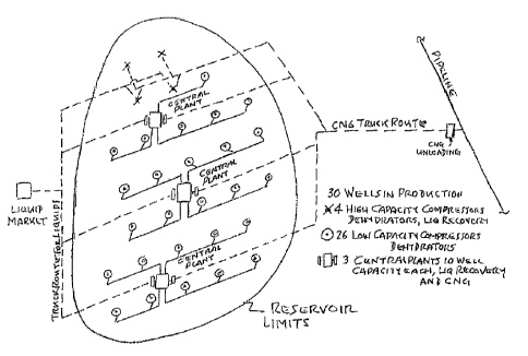
Figure 7, 8, 9 and 10 show plan views of four typical developments of
gas fields.
Figures 11A, 11B, 11C and 11D show four arrangements for cooling
CNG before it enters the tanks, where Figure 11A shows Joule Thomson cooling
CA 02820733 2017-01-27
from interstage, Figure 11B shows Joule Thomson cooling from discharge, Figure
11C shows cooling CNG by external coolant and Figure 11D shows cooling of the
recycle stream.
Figure 12 is a graph showing the gas temperature profile related to the
5 percentage filling of a tank capacity.
DETAILED DESCRIPTION
Figure 1 shows reduction of flare gas by recovering propane plus and
illustrates a typical facility where the quantity of flare gas is decreased by
stripping
the gas of liquefied components such as LPG and stabilized condensate.
Recovery
10 of liquids typically reduces flaring by as much as 20% depending on the
composition
of the flare gas. Figure 1 is a process scheme based on the Clausius Clapeyron
Expansion Principle to recover propane and heavier hydrocarbon components. The
advantage of this process over conventional turbo expander processes is its
extreme flexibility, especially its wide operating range in handling varying
flow rates.
15 The LPG produced meets commercial standards for marketing and the
stabilized
condensate meets commercial standards for Reid vapor pressure. Details of the
process may vary somewhat depending on operating conditions, the composition
of
the gas and the required specifications for the products.
In Figure 1, items 100 and 101, which are both upstream of the
20 proposed patented process scheme, represent typIcal production equipment
in the
field such as a valve 100, to control pressure and flow of the wellstream, and
separation equipment 101, which divides the incoming stream into its three
CA 02820733 2017-01-27
31
respective phases of gas, hydrocarbon liquid, and water. For gas wells, this
equipment would primarily be gravitational separators and for oil wells, the
equipment is a combination of gravitational separators and oilfield treaters.
For gas
wells, if liquids from the separation equipment were sufficient to justify
production in
spite of a lack of market for the gas, then the byproduct gas would
conventionally be
sent to flare stack 102, likewise for oil batteries. The non-marketable gas is
sent to
flare.
By the use of this invention, instead of sending what is considered to
be waste gas to flare, it is diverted to a compressor 103 and a gas discharge
cooler
101, which raises the pressure to approximately 500 PSIA at 120 F. The gas
then
flows to a desiccant dehydrator 106A/B/C, which may be either two tower or
three
tower units, depending on conditions, and it may also sometimes remove a small
quantity of hydrocarbon liquid in addition to water. For regeneration, either
dry
product gas or wet inlet gas can be used to regenerate the beds of desiccant.
Regeneration gas is typically heated in a salt bath heater 107 and cooled in
an air
cooled heat exchanger 108 which condenses water and possibly some hydrocarbon
liquid which is removed from the regeneration stream in separator 109. The gas
from
the separator 109 then recombines with inlet gas entering the desiccant
towers.
Downstream of the dehydrator the dry gas is divided into two streams,
one of which is cooled in a gas/gas exchanger 110, then proceeds to a propane
refrigerated chiller 118, then to an expansion valve 119, then enters the gas
fractionator 120 below the bottom stage. The other dry gas stream flows to a
CA 02820733 2017-01-27
32
compressor 111 and a discharge cooler 112 which raises the pressure to
approximately 1500 PSIA at 1200F. The gas is then cooled in Gas/Gas exchangers
113 and 115 and in propane refrigerated chiller 114. Propane is the
refrigerant
normally used in gas processes but other commercial refrigerants could also be
used. The chilled gas then enters the expansion valve 116 which lowers the
pressure to approximately 450 psia, resulting in an extremely cold feed stream
entering the gas fractionator 120 at the top stage of the column. In the
Figure 1
version of the process there is no market for the gas, so the residue gas from
the
gas fractionator is sent to flare 102 after the liquids have been stripped
out.
The bottom liquid product from the gas fractionator 120 contains the
propane and heavier components which are to be recovered, but the liquids are
heavily loaded with light gases, mainly methane and ethane which should be
separated from the liquid product. Most of these light gases can be flashed
off in the
deethanizer's feed flash drum 121 without losing a significant amount of
recoverable
liquid. The overhead vapor from the flash drum is sent to flare stack 102.
Bottom liquid from the flash drum 121 is reduced in pressure by a let-
down valve which produces a very cold feed stream which enters on the top
stage of
the deethanizer 126. The deethanizer is typically a top feed fractionator
without a
reflux condenser but with a bottom reboiler 127 which produces the necessary
temperature profile in the column. Normally the specification imposed on the
bottom
product from the deethanizer is that the molar C2/C3 ratio should not exceed
2%.
The light gases, mainly methane and ethane that are stripped from the liquid
in the
CA 02820733 2017-01-27
33
deethanizer are sent to the flare 102. Losses overhead of valuable liquids in
the
deethanizer overhead vapor are not significant.
The bottom liquid that flows from the deethanizer contains the liquid
product that can be recovered from the flare gas. The purpose of the
debutanizer
128 is to separate the incoming mixture into the final products, normally
Liquefied
Petroleum Gas (LPG), a mixture of volatile hydrocarbons consisting of mainly
propane and butane, and stabilized condensate, consisting mainly of pentanes
and
heavier. The debutanizer feed enters at about mid stage of the column, and the
feed
stream is often boosted in pressure with a pump so that the reflux condenser
can
use ambient air as coolant. The debutanizer has an air cooled reflux condenser
129
and a bottom reboiler 130.
The LPG is a pressurized product so should be stored under pressure.
It may be stored on site in a stationary tank to be offloaded into a propane
truck, or it
could be loaded directly into a trailer stationed at the site to be picked up
and
delivered to market as required. The commercial specification that normally
applies
to the LPG is that the 02/03 ratio should not exceed 2%. This ratio is
determined in
the deethanizer.
The bottom product is stabilized condensate which normally is
produced with a Reid Vapor Pressure specification not exceeding 12 psia. From
a
single source such as a small well the quantity of stabilized condensate can
be
relatively small. The most convenient way to handle it is to recycle it back
to the inlet
separation facility 101 and combine it with the liquid hydrocarbon leaving the
inlet
CA 02820733 2017-01-27
34
separator. Alternatively, the stabilized condensate could be cooled by tube
and shell
or by air cooled heat exchanger, and then stored on site in a small
atmospheric tank.
The condensate has been de-gassed so has very low vapor pressure to enable
storage by atmospheric pressure. It could be trucked to market when the on-
site
tank was full.
The process equipment in Figure 1 is self contained and provides a
complete processing facility when installed on an individual gas well or oil
battery.
Figure 1 b is a simplified block diagram of Figure 1 showing a typical
facility where the quantity of flare gas is decreased by stripping the gas of
liquefied
components such as LPG and stabilized condensate.
In Figure 2 is shown an arrangement for the total recovery of CNG and
liquid from flare gas. The details of the upstream production facilities,
compressors,
dehydrators, and liquid recovery packages described in Figure 1 apply also to
Figure
2. The only difference is that instead of sending residue gas to flare it is
compressed, cooled and loaded directly into special CNG tanker trucks to be
transported as commercial product to market.
The combined overhead vapors from the gas fractionator, the feed
flash drum, and deethanizers, after transferring cold energy back into the
deep cut
process, are compressed in two stages to a final pressure of approximately
3415
psia. This choice of the final pressure depends on the design of the tanks on
the
trucks. The inter-stage discharge has a back pressure valve 135 to hold a
constant
back pressure on the first stage compressor 131 downstream of the air cooled
CA 02820733 2017-01-27
exchanger 132 during the initial stages of filling when tank pressure is below
inter-
stage pressure. This is to provide Joule Thomson cooling of the gas through
valve
135 as it flows into the tank 137 from the time when the tank is empty until
the tank
pressure equals inter-stage pressure. Cooling the gas during the early stages
of
5 filling
canprevent the final temperature in the tank from rising too high. When tank
pressure reaches inter-stage pressure the gas flow is diverted from the back
pressure valve 135 to the Stage 2 compressor 133 and its discharge cooler 134
which then starts up and continues to fill the tank until fully charged. The
CNG is
metered 136 at the loading station.
10 As the tanks
near their loaded capacity a second truck arrives which is
empty. It is connected up in readiness to receive its cargo of CNG when the
first
truck is fully loaded. Flow of gas during loading is continuous without
interruption.
The loaded truck departs and carries its cargo to the destination where it is
unloaded
under controlled conditions into the users system.
15 Figure 2b is
a simplified block diagram of Figure 2 showing a typical
facility where the flare gas is eliminated by stripping the gas of liquefied
components
such as LPG and stabilized condensate and the residual gas is compressed,
cooled
and loaded directly into special CNG tanker trucks to be transported as
commercial
product to market.
20 Figure 3
shows a reduction of flare gas by recovering ethane and
heavier components and is generally similar in principle to the process
described in
Figure 1. Like Figure 1, the Figure 3 process scheme is intended to be
installed at
CA 02820733 2017-01-27
36
individual well sites or oil batteries and it includes compression,
dehydration, and
recovery of commercial products, but the difference is that the Figure 3
process also
recovers ethane in addition to LPG and stabilized condensate. Ethane is a
volatile
component and at normal ambient temperatures it is probably a gas having a
vapor
pressure approaching 1000 psia. Therefore the usual way to ship ethane is as a
gas
in a pipeline, or it could be compressed and shipped by truck, the same as
CNG. Or,
if it could be chilled to 0 F or less it could be shipped as a liquid at about
250 psia,
provided that it could be continuously cooled. Figure 3 recovers ethane as a
gas but
does not show how it is shipped to market.
The production facilities 100 and 101 upstream of the process in Figure
3 are identical to the corresponding items 100 and 101 in Figure 1. The
compressors and the dehydrator in Figure 3 are also identical to those in
Figure 1.
The differences are all in the deep cut liquid recovery process.
The first difference occurs when the dry gas is split into two streams.
The first stream is cooled by a gas/gas exchanger 110 then flows to a flash
drum
117, the overhead vapors from which flow to chiller 118 and valve 119 and
enter the
gas fractionator 120 as a bottom feed. Figure 1 had no flash drum. The second
dry
gas stream flows to compressor 111, cooler 112, exchangers 113 and 115,
chiller
114, then through expansion valve 116 to produce an extremely cold stream that
enters the gas fractionator 120 as the top feed, the same as in Figure 1.
Although there are physical similarities to Figure 1, the process to
recover ethane in general requires lower temperatures in the gas fractionator
than
CA 02820733 2017-01-27
37
are required to recover propane and heavier as in Figure 1. As before, the
residue
gas from the gas fractionator is sent to flare. The bottom liquid from the gas
fractionator is sent to the second fractionator in the line, the demethanizer
(122).
For the recovery of ethane the process requires an additional
fractionating column, the demethanizer, 122 to remove light gases, principally
methane from the liquid mixture. The bottom product from the gas fractionator
120 is
reduced in pressure by a level control valve and then enters the demethanizer
122
at a very low temperature as top feed. Liquids from the flash tank 117 also
enter the
demethanizer at about the midpoint of the column as a second feed. Because the
demethanizer 122 has a very cold top feed a reflux condenser is not required.
A
bottom reboiler 123 provides heat for the necessary temperature profile in the
column. The overhead vapor from the demethanizer has no market so is sent to
flare. The specification imposed on the bottom product from the demethanizer
is
typically a molar ratio of C1/C2 not exceeding 2%. This is to enable a
relatively pure
ethane stream to be produced in the following fractionator. The bottom liquid
leaving
the demethanizer contains all the commercial products to be recovered by the
process. Subsequent fractionation just divides the liquid into the desired
products.
The bottom liquid exiting the demethanizer 122 flows downstream and
enters the deethanizer 124 as feed at approximately the mid-point of the
column.
The purpose of this deethanizer is to separate the product, ethane gas, as
overhead
from the propane and heavier components in the feed. Since methane and light
gases have already been removed, and since a relatively high reflux ratio is
used in
CA 02820733 2017-01-27
38
the deethanizer 124, a relatively pure ethane product can be produced. The
deethanizer has a refrigerated reflux condenser 125 and a bottom reboiler 126.
The
bottom product from the deethanizer is a liquid mixture of propane and
heavier,
which, as in Figure 1, flows to the debutanizer.
The bottom product that flows from the deethanizer 124 contains LPG
and stabilized condensate as a liquid mixture and it is the function of the
debutanizer
128 to separate the mixture into the desired commercial products. The
operation and
function of the debutanizer is exactly as described previously for Figure 1.
Figure 4 shows the total recovery of CNG and liquid from flare gas and
the details of the upstream production facilities, compressors, dehydrators
and liquid
recovery packages described in Figure 3 apply also to Figure 4. The only
difference
is that instead of sending residue gas to flare it is compressed, cooled, and
loaded
directly into special CNG tanker trucks to be transported as commercial
product to
market.
The deep cut process detailed in Figure 4 recovers ethane in addition
to LPG and stabilized condensate. Ethane leaves the process in the form of a
gas at
a pressure probably below 200 psia. There are various ways to deliver the
ethane to
market.
a) It could be compressed and delivered by truck using methods
similar to the CNG technology
b) It could be transported as a liquid at about 250 psia in a truck
refrigerated to below 0 F
CA 02820733 2017-01-27
39
c) If an
ethane pipeline was in the area, ethane could be shipped
by pipeline. Details of the delivery method for ethane have not been detailed
in
Figure 4.
The combined overhead vapors from the gas fractionator and the
demethanizer after transferring cold energy back into the deep cut process,
are
compressed in two stages to a final pressure of approximately 3415 psia. The
choice
of final pressure depends on the design of the tanks on the trucks. The inter-
stage
discharge has a back pressure valve 135 to hold a constant back pressure on
the
first stage compressor 131 down-stream of the air cooled exchanger (132)
during
the initial stages of filling when tank pressure is below inter-stage
pressure. This is to
provide Joule Thomson cooling of the gas through valve 135 as it flows into
tank 137
from the time when the tank is empty until the tank pressure equals inter-
stage
pressure. Cooling the gas during the early stages of filling can prevent the
final
temperature in the tank from rising too high. When tank pressure reaches inter-
stage
pressure the gas flow is diverted from the back pressure valve 135 to the
stage 2
compressor 133 and its discharge cooler 134 which then starts up and continues
to
fill the tank until fully charged. The CNG is metered at the loading station
in meter
136.
As the tanks near their loaded capacity a second truck arrives at the
loading station which is empty. It is connected up in readiness to receive its
cargo of
CNG when the first truck is fully loaded. Flow of gas during loading is
continuous
without interruption. As flow is transferred from one truck to the other, the
loaded
CA 02820733 2017-01-27
truck departs and carries its cargo to the destination where it is unloaded
under
controlled conditions into the users system.
Figure 5 shows total recovery of CNG and liquid from flare gas with rich
feed as where the same references are used as in Figure 1, 2, 3 and 4. 101 is
the
5 three-phase
inlet separator as before, but in this case is integral part with the liquid
recovery system. Item 138 is the liquid stabilizer which fractionates the
hydrocarbon
liquid from the inlet separator.
Feed gas that typically enters the deep cut plant is single phase gas
which contains no appreciable amount of hydrocarbon liquid because either the
gas
10 is lean and
is inherently free of liquid as it exits the well or possibly because the free
liquid has already been removed by separation equipment upstream of the deep
cut
facility.
However in some cases the gas, as it leaves the well, contains
significant quantities of free liquid, and if there are no separation
facilities upstream,
15 it is
necessary to provide additional equipment to handle the free liquids entering
the
system from the inlet stream. The complicating factor in processing these
inlet
hydrocarbon liquids is that they can be water saturated and in addition to
dissolved
water, can typically contain 1,000 to 5,000 ppm of entrained water droplets in
a very
fine dispersion.
20 It is
difficult to remove water from liquid hydrocarbons to the level
necessary to permit processing the liquids at cryogenic temperature. The
processing
of these liquids should therefore be done at temperatures safely above hydrate
of
CA 02820733 2017-01-27
41
freezing temperatures. It is first necessary to use gravitational separation
to separate
the inlet stream into its respective three phases of gas, hydrocarbon liquid
and free
water. The gas proceeds from the inlet separator to compression and
dehydration as
prescribed previously and the free water is sent to disposal. The water wet
hydrocarbon liquid from the inlet separator are then fractioned to produce an
overhead product consisting of light gases which are recycled back to the
inlet
separator. The bottom liquid product should meet the necessary specifications
determine the design of the fractionator. The liquid specification is sometime
12 psia
Reid vapor pressure, or if the liquid is to be processed for ethane recovery
the liquid
specification is typically a methane/ethane ration of 1%. If the liquid is
being
processed to recover propane and heavier, the bottom product is typically an
ethane/propane ration not exceeding 2%. The fractionation process normally
drives
almost all of the water overhead, either as water vapor or as liquid from a
water draw
off tray. But the bottom liquid can still contain traces of water so should
not enter this
cryogenic plant unless it is first dehydrated.
If the plant is designed to recover propane and heavier, the stabilizer
strips the liquid of ethane and other light gases, so the slightly wet liquid
can be sent
as feed to the debutanizer without causing excessive ethane content in the
LPG.
The minor amount of water in the feed is not a problem in this debutanizer
because
it runs hot. Also, the amount of water is so small it does not exceed
allowable limits
in the products.
CA 02820733 2017-01-27
42
Figure 6 shows an arrangement for Multiple Low Flow Wells Feeding
Into a Central Plant where the most likely application for this patented
technology is
for relatively small gas wells which suffer a severe reduction in gas
production within
a fairly short time after startup. Initially that gas flow rate may typically
be about 2.5
MMscfd, declining gradually by about 80% to a stable, long term flow rate of
about
0.5 MMscid.
Figures 1, 2, 3, and 4 show various process configuration to handle the
brief period of maximum flow following initial startup for each individual
well. The
processes described in those figures are of self contained equipment packages
which intake raw, unprocessed, water saturated gas and produce marketable
commercial products. These equipment packages are basically intended to be
temporarily installed at a well site to process the gas from a single well for
the
duration of the high flow phase of the operation.
When gas production falls to its minimum stable flow rate, the initial
high capacity process package is too big to efficiently process the very low
gas flow,
so the initial process package, being portable, is disconnected from the well
and
moved to a new well site which has a higher flow rate. The initial big unit
can be
replaced at this low flow well by a much smaller package consisting of a
miniature
compressor/dehydrator combination. Deep cut liquid recovery equipment
encounters
many difficulties when operating at extremely low flow rates, so the liquid
recovery
system is relocated to a central processing plant which handles the gas from a
CA 02820733 2017-01-27
43
cluster of several miniature compressor/dehydrator packages located at the low
flow
well sites.
Figure 6 shows a typical development where the self contained high
capacity units have been replaced by seven of the miniature
compressor/dehydrator
combinations, each of which sends gas by pipeline to the central gas plant,
from the
seven well sites. The particular example shown in Figure 6 recovers CNG, LPG
and
stabilized condensate in a deep cut facility at the central station. Each of
these
products is shipped to market by truck. For CNG, the gas is loaded directly
into
tanker trailers on a continuous basis. CNG trailers are available on site
continuously
as required so that flow is not interrupted. For LPG, Figure 6 shows a
stationary
pressurized LPG tank on site which is pumped periodically into a propane
tanker
truck when the stationary tank on site is full. Alternatively, a propane
trailer can be
stationed on site at the central plant which takes the place of the stationary
tank,
provided that a trailer is on site continuously. When one propane tanker is
full a
second one is on site, already connected and ready to take on its cargo of
LPG. For
stabilized condensate, the anticipated production is probably very small, so a
small
atmospheric storage tank on site at the central plant is sufficient, to be
pumped out
on a weekly or bi weekly basis and trucked to market. All products leaving the
central plant are metered before loading.
Equipment numbers applicable to Figure 6 are the same as
corresponding items of equipment in Figure 2.
CA 02820733 2017-01-27
44
As an alternative to desiccant dehydration at the well-site, it may be
practical to use glycol dehydration and use desiccant dehydration at the
central
plant.
Figures 7, 8, 9, 10 show an arrangement for typical development of gas
field where the four figures illustrate a typical case of the various stages
in the
development of a small gas field having a total of thirty marginal gas wells.
Figure 7
shows ten wells tied in, Figure 8 shows twenty wells tied in, Figure 9 shows
all thirty
wells tied in and in production but with the final four wells still in their
initial high
production phase. Figure 10 shows the field fully developed with all thirty
wells
configured for long term low volume production. The three stage development in
this particular example had ten wells per stage and three central plants
serving ten
wells each when the plan was complete.
The characteristics of this reservoir in the example are typical of many
tight gas reservoirs, especially shale gas reservoirs, which have an initial
flow which
can be five times as much as their long term steady flow rate. Usually the
deliverability tends to fall quite rapidly following the high production rate
following
startup. High flow for this type of well might be approximately 2.5 MMscfd
which
would decline over time to a stable flow of about 0.5 MMscfd which would then
continue almost indefinitely. The figures in this example suggest a
development plan
for this type of field.
The development scheme for this field is to take advantage of the brief
period of maximum production by installing portable self contained processing
CA 02820733 2017-01-27
facilities which can handle the high flow period which on an individual well
basis is
complete and can produce CNG, LNG stabilized condensate, and possibly in some
cases, ethane. This scheme enables the field to get into production quickly
based on
very few wells tied in and using miniature processing equipment to begin
generating
5 revenue right away from the sale of gas and liquids. The high flow
facility at each
well site is complete and self contained requiring only utilities from the
power grid if
available.
The scheme for this particular example calls for using four high
capacity portable processing packages which are installed either one at a time
or all
10 four simultaneously in a tight cluster that can enable a planned
expansion of a
gathering system when the high capacity units are moved onto new wells to be
replaced by low capacity compressor / dehydrator packages. The four high
capacity
units, each processing 2.5 MMscfd for a total of 10 MMscfd are moved step by
step
until all ten wells of the first ten well clusters are in production, four at
high capacity
15 and six at low capacity producing 0.5 MMSCFD each for an overall
production of 13
MMscfd. As each set of four high volume units run down to 0.5 MMscfd, the
portable high capacity units are moved on to new high volume wells to be
replaced
by miniature compressor/dehydrator combinations designed for 0.5 MMscfd each.
Meanwhile, this central plant which uses a deep cut cryogenic process to
produce
20 CNG, LNG and Stabilized Condensate should be ready to accept the dry field
gas
from the low volume compressor/dehydrator units as soon as they are installed.
Dry
gas arrives at the central plant at about 500 psia.
CA 02820733 2017-01-27
46
Development proceeds in this way until the first cluster of ten wells is in
production. Figure 7 illustrates this, showing four high capacity wells and
six low
capacity wells which at this point are sending 3 MMscfd to the central plant
which is
designed for an ultimate capacity of 5 MMscfd when all ten wells are tied in
to the
plant. The four high capacity self contained units in Figure 7 are processing
10
MMscfd in total and sending commercial products directly to market by truck,
The
central plant likewise sends commercial products to market by truck.
Among the things to consider in preparing a development plan is the
location of the central plant among the cluster of wells. It should be placed
so that
the cost of the gathering system is minimized. The design and location of well
stream metering equipment should also be considered if it is within the scope
of the
project. Reservoir engineers can recommend the sequence of developing new
wells.
For diagrammatic simplicity Figures 7 to 10 show development proceeding in an
orderly way from south to north. Reservoir science, taking account of the
delicate
and sometimes temperamental nature of tight reservoirs may dictate otherwise.
Figure 8 shows the first cluster of ten wells fully developed and tied in
to the central plant. All ten wells of the second cluster are in production
with four
wells in high production mode and six wells in low production and tied in to
control
plant #2. As in Figure 7, CNG, LNG, and stabilized condensate are delivered to
market by truck. The example shows the CNG being unloaded into a pipeline;
this
probably requires a compressor to empty the truck. Delivery of CNG for
industrial or
domestic users may not require a compressor.
CA 02820733 2017-01-27
47
Figure 9, like Figure 8 shows the next stage of development with all
thirty wells in production with the final four wells still in their high
volume mode. Six
wells are tied into the gathering system and are producing into central plant
# 3.
Figure 10 shows the field fully developed with all 30 wells producing at
0.5 MMscfd each and tied in to their respective central plants.
This example illustrates the development of only one hypothetical field.
The general principles are applicable to many fields but each case is
different and
the development plan should be specific to each situation.
Figures 11A to 11D show a number of arrangements for cooling CNG
before it enters the tanks, assuming the truck tanks are considered empty at
165
psia and full at 3415 psia. Compression of gas into the tanks begins at 165
psia and
ends at 3415 psia. As the tanks are filled, the gas already in the tanks
increases in
pressure and becomes warmer due to heat of compression. If the discharge
cooler
of the compressor cools the gas to 120 F and if no further cooling occurs
except
convective cooling from the cool walls of the tank, the final average
temperature in
the tanks can be approximately 160 F. It is desirable to cool the gas further
to
increase the payload carried in the tanks. For example, if the temperature
could be
lowered by 30 F the weight of gas carried in the tanks would increase by
approximately 8%. Another issue to consider if composite materials are used in
the
tanks, excessive temperature can degrade the non metallic components in the
tank,
increasing possible risk of failure. As compression proceeds the gas initially
in the
tank is pushed to the far end of the tank and because this initial gas
experiences the
CA 02820733 2017-01-27
48
greatest change in pressure it also experiences the greatest increase in
temperature. The far end of the tank becomes very hot while the inlet end
remains
cool. To prevent this misdistribution of temperature the inlet nozzle is
connected to
an inlet sparger that runs the full length of the tank to evenly distribute
the gas as it
enters the tank. This can produce an even, average, temperature rise for the
full
length of the tank, rather than one hot end and one cool end. The sparger runs
along
the bottom of the shell of the tank to act as a pickup duct for any liquid
that may
condense in the tank.
Figure 11A shows an arrangement for Joule Thomson cooling from
interstage where maintaining a back pressure on the interstage gas and choking
it
directly into the trucks' tanks produces a maximum temperature drop of about
50 to
60 F for the gas initially flowing into the empty tank. This cooling effect
can continue
until the tank pressure equals interstage pressure. At that time the back
pressure
valve 135 is by passed and compressor 133 and cooler 134 start up and gas
fiowing
into the tank can be constant at approximately 120 F. This system adds to
horsepower hours to produce cooling.
=
CA 02820733 2017-01-27
49
Figure 11B shows an arrangement for Joule Thomson cooling from
discharge which uses Joule Thomson for cooling by maintaining a back pressure
on
the discharge gas entering the tank. The advantage of this system is that the
back
pressure setting is variable between interstage pressure and final pressure.
As
before, when tank pressure equals the back pressure, the choke is bypassed.
Joule
Thomson cooling adds to horse power hours to produce cooling.
Figure 110 shows an arrangement for cooling CNG by external coolant
where the discharge air cooler lowers the gas temperature to approximately 120
F,
depending on ambient temperature. If an alternate coolant such as cooling
water is
available for exchanger (138) it possibly lowers the temperature by a further
40 F,
Or, if refrigeration is used it lowers the inlet temperature sufficiently that
that the final
average temperature in the tanks can be about 120 F. The advantage of an
external cooling is that it is constant throughout the filling cycle.
Excessive cooling
should be avoided however to avoid extreme cryogenic temperatures when the
tanks are unloaded.
Figure 11D shows an arrangement for cooling of recycle stream where
instead of precooling the gas before it enters the tank so that when it
undergoes
compression inside the tank it is not too hot, an alternate approach is to
recycle the
gas in the tanks after it has become heated due to compression through a
cooler
139 to remove the heat of compression directly. An external coolant such as
ambient
air or cooling water can be used. This cooled recycle gas is combined with
inlet gas
entering the tanks. A means to circulate the recycle gas should be used.
Because
=
CA 02820733 2017-01-27
pressure losses in the recycle circuit are very low, an educator (140) can be
used to
provide the motive power as shown in Figure 11D. Recycle gas flow through the
eductor should be positively controlled to avoid adding excessive loads to the
compressor (133). Alternately a blower or compressor could be used in the
circuit to
5 recycle the cooled gas.
Figure 12 shows the temperature profile during the filling phase of a
tank: the choking effect of the back pressure valve on the final-stage
compressor
produces cooling. The cooling at the beginning of the fill cycle is sufficient
to reduce
the final average gas temperature to a desired level.