Note: Descriptions are shown in the official language in which they were submitted.
I
STROLLER
CROSS REFERENCE TO RELATED APPLICATIONS
[0001]
This application is based upon and claims priority to the prior Japanese
Patent
Application No. 2012-154831 filed on July 10, 2012 and the prior Japanese
Patent
Application No. 2012-259873 filed on November 28, 2012.
BACKGROUND OF THE INVENTION
[0002]
Field of the Invention
The present invention relates to a stroller capable of letting babies ride
thereon in
such a manner that the babies are seated in a back and front direction.
[0003]
Background Art
As disclosed in US2002-033588, strollers capable of transporting a plurality
of
babies are used. As such strollers, there are known strollers of the type in
which babies
are seated in the lateral direction, and a stroller of a type in which babies
are seated in the
back and front positions. In the stroller of either type, a caregiver of the
babies steers the
stroller from a rear side thereof, while grasping a handle disposed on a rear
part of the
stroller. Generally, when the stroller travels along a curved path, the
stroller is turned
about an axis of a rear wheel position in the back and front direction, so as
to change a
traveling direction (facing direction) of the stroller.
[0004]
However, in the stroller of a type in which babies are seated in the back and
front
positions, i.e., in the tandem-type stroller, an overall length from the back
to the front is
longer. Thus, in the stroller of a type in which babies are seated in tandem,
the center of
gravity of the stroller transporting the
CA 2820907 2019-11-15
CA 02820907 2013-07-08
2
babies is positioned largely forward of a turning center of the
stroller about which the stroller is turned to change its traveling
direction. On the other hand, the handle to which a force is
applied by the steering person is positioned near to the turning
center of the stroller about which the stroller is turned so as to
change its traveling direction, in the back and front direction.
Thus, when the stroller Is turned, it Is necessary for the steering
person to apply a very large force to the handle, which makes
the steering difficult.
BRIEF SUMMARY OF THE INVENTION
[0005]
The present invention has been made in view of the
above circumstances. The object of the present invention is to
improve the steerability of a stroller in which a plurality of
babies can be seated in the back and front positions.
[0006]
A first stroller according to the present invention is a
stroller including:
a front leg;
a middle leg located rearward of the front leg;
a rear leg located rearward of the middle leg;
a front-wheel holding mechanism provided on the front
leg, the front-wheel holding mechanism being configured to
rotatably and turnably hold a front wheel;
a middle-wheel holding mechanism provided on the
middle leg, the middle-wheel holding mechanism being
configured to rotatably and unturnably hold a middle wheel; and
a rear-wheel holding mechanism provided on the rear leg,
the rear-wheel holding mechanism being configured to rotatably
and turnably hold a rear wheel,
wherein the stroller is capable of letting babies ride
thereon in such a manner that the babies are seated in a back
to front position.
[0007]
The first stroller stroller according to the present
CA 02820907 2013-07-08
3
invention may further include:
a handle;
a fourth link element pivotably joined, at a rear portion
thereof, to the handle, and pivotably joined to an upper portion
of the rear leg;
a first link element pivotably joined, at a rear portion
thereof, to the handle, and pivotably joined, at a front portion
thereof, to the front leg;
a second link element pivotably joined to a front portion
of the fourth link element, and pivotably joined to an
intermediate portion of the first link element;
a third link element pivotably joined, at a rear portion
thereof, to the second link element, and pivotably joined to an
upper portion of the front leg and an upper portion of the
middle leg;
a fifth link element pivotably joined to the second link
element and the middle leg, respectively; and
a sixth link element pivotably joined to the handle and
the rear leg, respectively.
In the first stroller according to the present invention, a
pair of the front legs may be provided to be spaced apart from
each other in a width direction; a pair of the middle legs may be
provided to be spaced apart from each other in the width
direction; a pair of the rear legs may be provided to be spaced
apart from each other in the width direction; the front-wheel
holding mechanism may be provided on each front leg; the
middle-wheel holding mechanism may be provided on each
middle leg; and the rear-wheel holding mechanism may be
provided on each rear leg. Alternatively, in the first stroller
according to the present invention, the front leg may include a
pair of front-leg extending parts located to be spaced apart from
each other in a width direction, and a front-leg connection part
connecting the pair of front-leg extending parts; a pair of the
middle legs may be provided to be spaced apart from each
other in the width direction; a pair of the rear legs may be
provided to be spaced apart from each other in the width
CA 02820907 2013-07-08
4
direction; the front-wheel holding mechanism may be provided
on the front connection part; the middle-wheel holding
mechanism may be provided on each middle leg; and the
rear-wheel holding mechanism may be provided on each rear
leg. Alternatively, in the first stroller according to the present
invention, a pair of the front legs may be provided to be spaced
apart from each other in a width direction; a pair of the middle
legs may be provided to be spaced apart from each other in the
width direction; the rear leg may include a pair of rear-leg
extending parts located to be spaced apart from each other in
the width direction, and a rear-leg connection part connecting
the pair of rear-leg extending parts; the front-wheel
holding
mechanism may be provided on each front leg; the
middle-wheel holding mechanism may be provided on each
middle leg; and the rear-wheel holding mechanism may be
provided on the rear-leg connection part. Alternatively, in the
first stroller according to the present invention, the front leg
may include a pair of front-leg extending parts located to be
spaced apart from each other in a width direction, and a
front-leg connection part connecting the pair of front-leg
extending parts; a pair of the middle legs may be provided to be
spaced apart from each other in the width direction; the rear leg
may include a pair of rear-leg extending parts located to be
spaced apart from each other in the width direction, and a
rear-leg connection part connecting the pair of rear-leg
extending parts; the front-wheel holding mechanism may be
provided on the front-leg connection part; the middle-wheel
holding mechanism may be provided on each middle leg; and
the rear-wheel holding mechanism may be provided on the
rear-leg connection part.
[0008]
A second stroller according to the present invention is a
stroller including:
a front leg;
a rear leg located rearward of the front leg;
a middle leg located rearward of the middle leg;
CA 02820907 2013-07-08
a first link element pivotably joined, at a front portion
thereof, to the front leg;
a handle pivotably joined to a rear portion of the first link
element;
5 a fourth link
element pivotably joined, at a rear portion
thereof, to the handle, and pivotably joined to an upper portion
of the rear leg;
a second link element pivotably joined to a front portion
of the fourth link element, and pivotably joined to an
intermediate portion of the first link element;
a third link element pivotably joined, at a rear portion
thereof, to the second link element, and pivotably joined to an
upper portion of the front leg and an upper portion of the
middle leg;
a fifth link element pivotably joined to the second link
element and the middle leg, respectively; and
a sixth link element pivotably joined to the handle and
the rear leg, respectively.
In the second stroller according to the present invention,
a pair of the front legs may be provided to be spaced apart from
each other in a width direction; a pair of the middle legs may be
provided to be spaced apart from each other in the width
direction; and a pair of the rear legs may be provided to be
spaced apart from each other in the width direction.
Alternatively, in the second stroller according to the present
Invention, the front leg may include a pair of front-leg extending
parts located to be spaced apart from each other in a width
direction, and a front-leg connection part connecting the pair of
front-leg extending parts; a pair of the middle legs may be
provided to be spaced apart from each other In the width
direction; and a pair of the rear legs may be provided to be
spaced apart from each other in the width direction.
Alternatively, in the second stroller according to the present
invention, a pair of the front legs may be provided to be spaced
apart from each other in the width direction, a pair of the
middle legs may be provided to be spaced apart from each
CA 02820907 2013-07-08
6
other in the width direction, and the rear leg may include a pair
of rear-leg extending parts located to be spaced apart from
each other in the width direction, and a rear-leg connection part
connecting the pair of rear-leg extending parts. Alternatively,
in the second stroller according to the present Invention, the
front leg may include a pair of front-leg extending parts located
to be spaced apart from each other in the width direction, and a
front-leg connection part connecting the pair of front-leg
extending parts, a pair of the middle legs may be provided to be
spaced apart from each other in the width direction, and the
rear leg may include a pair of rear-leg extending parts located
to be spaced apart from each other in the width direction, and a
rear-leg connection part connecting the pair of rear-leg
extending parts.
[0009]
The first or second stroller according to the present
Invention may further include a first seat unit for letting a baby
ride thereon and a second seat unit for letting a baby ride
thereon, wherein the second seat unit is supported by a position,
of the first link element, located rearward of the position at
which the first link element is joined to the second link element,
and the first seat unit is supported by the first link element on a
position that is forward of the second seat unit.
[0010]
The first or second stroller according to the present
invention may further include a first seat unit for letting a baby
ride thereon and a second seat unit for letting a baby ride
thereon, wherein the first seat unit is supported by the third link
element, and the second seat unit is supported by the fourth
link element.
[0011]
The first or second stroller according to the present
invention may further include a first seat unit for letting a baby
ride thereon and a second seat unit for letting a baby ride
thereon, wherein at least a portion of the first seat unit is
located between the front leg and the middle leg, in the back
CA 02820907 2013-07-08
7
and front direction of the stroller, and the second seat unit is
located rearward of the first seat unit, and at least a portion of
the second seat unit is located between the middle leg and the
rear leg, in the back and front direction of the stroller.
[0012]
The first or second stroller according to the present
invention may further comprise a stand member attached to a
lower portion of the handle, wherein the stroller in a folded
condition can stand by itself with only the stand member and
the rear wheel being grounded. According to such a stroller, a
space required for storing the stroller can be made smaller, In
addition, handling of the folded stroller can be significantly
improved.
[0013]
In the first or second stroller according to the present
Invention, the stand member may be swingably attached to the
handle and Is urged to be separated from the rear wheel.
According to such a stroller, a space required for storing the
stroller can be made further smaller.
[0014]
The first or second stroller according to the present
invention may further include a braking mechanism capable of
restricting rotation of the middle wheel. According to such a
stroller, rotation of the wheel of the stroller can be stably
restricted, while the braking mechanism can be made smaller
and simplified.
[0015]
In the first or second stroller according to the present
invention, a pair of the middle legs may be provided to be
spaced apart from each other in the width direction; the
middle-wheel holding mechanism may be provided on each
middle leg; and there may be provided a braking mechanism
capable of restricting rotation of the pair of middle wheels held
on the middle-wheel holding mechanisms. According to such a
stroller, rotation of the wheel of the stroller can be stably
restricted, while the braking mechanisms can be made smaller
CA 02820907 2013-07-08
8
and simplified.
[0016]
In the first or second stroller according to the present
invention, the braking mechanism may include: a cam member
that is located on a position between the pair of middle-wheel
holding mechanisms or a position between the pair of middle
legs; and shaft members that are respectively disposed between
the cam member and the one middle wheel and between the
cam member and the other middle wheel; the cam member may
be movable between a first position and a second position;
when the cam member is moved, from the first position to the
second position, each shaft member may be moved outward in
the width direction to be engaged with the corresponding middle
wheel so as to restrict the rotation of the middle wheel; and
when the cam member Is moved from the second position to the
first position, each shaft member may be moved inward in the
width direction to release the engagement between the shaft
member and the corresponding middle wheel so as to enable
the rotation of the middle wheel. According to such a stroller,
by operating the one cam member, rotation of each of the pair
of middle wheels can be restricted. Namely, the rotation of the
wheel can be more reliably restricted by the simple operation.
[0017]
In the first or second stroller according to the present
invention, the braking mechanism may further include: an
operation member that is movable between a release position
and a restriction position, when the operation member is moved
from the release position to the restriction position, the
operation member being held as it is on the restriction position;
and a release member configured to release the operation
member held on the restriction position; when the operation
member is moved from the release position to the restriction
position, the cam member may be moved from the first position
to the second position; and when the operation member is
moved from the restriction position to the release position, the
cam member may be moved from the second position to the
CA 02820907 2013-07-08
9
first position. According to such a stroller, the cam member
disposed on a position between the pair of middle-wheel holding
mechanisms or a position between the pair of middle legs can
be remotely operated, whereby the operability of the braking
mechanism can be significantly improved.
[0018]
According to the first or second stroller according to the
present invention, the braking mechanism may further include
an operation member configured to operate the movement of
the cam member from the first position to the second position;
and the operation member may be supported on a rear
connection member that is located on a position between the
pair of rear legs or a position between the pair of rear-wheel
holding mechanisms. According to such a stroller, the cam
member disposed on a position between the pair of
middle-wheel holding mechanisms or a position between the
pair of middle legs can be operated from the rear side of the
stroller.
[0019]
In the first or second stroller according to the present
invention, the braking mechanism may further include socket
members respectively disposed between the cam member and
the one shaft member and between the cam member and the
other shaft member; each socket member may have a recess
opening outward in the width direction; and an inner end of the
shaft member in the width direction may be located in the
recess of the socket member, and the shaft member is relatively
movable in the width direction with respect to the socket
member. According to such a stroller, the cam member can be
operated without adjusting the rotational position of the middle
wheel.
[0020]
In the first or second stroller according to the present
invention, the braking mechanism may further include a first
urging member configured to urge the shaft member outward in
the width direction, and a second urging member configured to
CA 02820907 2013-07-08
urge the shaft member inward in the width direction.
[0021]
According to the present invention, it is possible to
improve the steerability of a stroller in which a plurality of
5 babies can be seated in a back to front position.
BRIEF DESCRIPTION OF THE DRAWINGS
[0022]
Fig. 1 is a perspective view of a first embodiment of the
10 present invention, showing, from a lateral side, a stroller in the
unfolded condition.
Fig. 2 is a perspective view showing, from the lateral side,
the stroller in Fig. 1 in the course of being folded.
Fig. 3 is a view showing, from the lateral side, the stroller
in Fig. 1 in the folded condition.
Fig. 4 is a diagrammatic view schematically showing a
structure of the stroller In Fig. 1.
Fig. 5 is a view corresponding to Fig. 4, showing a
modification example of a seat unit.
Fig. 6 is a view illustrating the action of the stroller that
is being turned.
Fig. 7 is a view for illustrating the action of a
conventional stroller being turned.
Fig. 8 is a view corresponding to Fig. 1, showing a
modification example of the stroller.
Fig. 9 Is a view corresponding to Fig. 3, showing the
stroller in Fig. 8 in the folded condition.
Fig. 10 is a view corresponding to Fig. 1, showing
another modification example of the stroller.
Fig. 11 is a view corresponding to Fig. 1, showing yet
another modification example of the stroller.
Fig. 12 is a view corresponding to Fig. 3, showing the
stroller in Fig. 11 in the folded condition.
Fig. 13 is a perspective view showing a part where a
braking mechanism of the stroller is provided.
Fig. 14 is a cross-sectional view of the part where the
CA 02820907 2013-07-08
11
braking mechanism of the stroller is provided.
Fig. 15 is a longitudinal sectional view of the part where
the braking mechanism of the stroller is provided.
Fig. 16 is a view corresponding to Fig. 15, showing the
braking mechanism In a condition different from the condition
shown in Fig. 15.
Fig. 17 is a partially enlarged view of Fig. 14.
Fig. 18 is a view corresponding to Fig 17, showing the
braking mechanism in a condition different from the condition
shown in Fig. 17.
Fig. 19 is a view corresponding to Fig. 17, showing the
braking mechanism In a condition different from the conditions
shown in Figs. 17 and 18.
DETAILED DESCRIPTION OF THE INVENTION
[0023]
An embodiment of the present invention will be described
herebelow with reference to the drawings. Figs. 1 to 6 are
views for explaining an embodiment of a stroller according to
the present invention.
[0024]
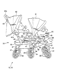
Figs. 1 to 3 show a stroller 10 in one embodiment of the
present invention. As shown in Fig. 1, the stroller 10 includes a
stroller body 15, a first seat unit 66 supported by the stroller
body 15, and a second seat unit 68 supported by the stroller
body 15. The first seat unit 66 and the second seat unit 68 are
places on which babies are seated, and are arranged to be
aligned back to front. Namely, the
illustrated stroller 10 is
constituted as a two-seater stroller of a tandem type. As well
shown in Fig. 4, the stroller body 15 includes a frame part 30
having legs 31, 34 and 37 and a handle 40, and wheel holding
mechanisms 21, 24 and 27 provided on lower portions of the
respective legs 31, 34 and 37.
[0025]
In addition, as shown in Figs. 2 and 3, the illustrated
stroller 10 can be folded such that the legs 31, 34 and 37 and
CA 02820907 2013-07-08
12
the handle 40 are brought close to each other. Many
constituent elements of the stroller body 15 are pivotably
coupled to each other, in order that the stroller can be folded.
[0026]
In this specification, the terms "front", "rear", "up",
"down", "back to front direction", "up and down direction" and
"lateral direction" regarding the stroller 10 and the constituent
elements of the stroller mean, unless otherwise specified,
"front", "rear", "up", "down", "back to front direction" (or "back
and front direction"), "up and down direction" and "lateral
direction", with respect to an operator who grasps the handle 40
to operate the stroller 10 in the unfolded condition, in particular,
the foldable stroller 10 in the unfolded condition. More
specifically, the "back to front direction" corresponds to a right
and left direction on sheet planes of Figs. 1 and 4. Unless
otherwise specified, the "front" is a side to which the operator
who pushes the handle faces. The right side of the sheet
planes of Figs. 1 and 4 is the front. Meanwhile, the "up and
down direction" is a direction perpendicular to the back and
front direction, and is a direction perpendicular to the ground on
which the stroller 10 rests. Thus, when the ground surface is a
horizontal surface, the "up and down direction" represents a
vertical direction. The "lateral
direction" is also a width
direction, and is a direction perpendicular both to the "back to
front direction" and the "up and down direction".
[0027]
The stroller 10 is described in more detail below with
reference to Figs. 1 to 4. The stroller 10 as a whole has a
substantially symmetrical structure about a central surface in
the width direction, which extends along the back to front
direction. As can be understood from Figs. 1 and 4, in the
stroller 10 in this embodiment, the frame part 30 includes the
pair of right and left front legs 31, the pair of right and left
middle legs 34, the pair of right and left rear legs 37, a pair of
right and left first link elements 41, a pair of right and left
second link elements 42, a pair of right and left third link
CA 02820907 2013-07-08
13
elements 43, a pair of right and left fourth link elements 44, a
pair of right and left fifth link elements 45, a pair of right and
left sixth link elements 46, and the handle 40. As can be well
understood from Figs. 1 to 3, the handle 40 has a U-shape, and
includes a pair of right and left handle extending parts 40a and
a handle connection part 40b extending between the pair of
handle extending parts 40a.
[0028]
As shown in Fig. 4, the first link element 41 is pivotably
joined, at a rear portion thereof, in particular, a rear end of the
rear portion in the Illustrated example, to a lower portion of the
corresponding handle extending part 40a of the handle 40, in
particular, a lower end of the lower portion of the handle
extending part 40a in the illustrated example. In addition, the
first link element 41 is pivotably joined, at a front portion
thereof, in particular, a front end of the front portion in the
illustrated example, to an intermediate portion of the
corresponding front leg 31. The second link element 42 is
pivotably joined, at a lower portion thereof, in particular, a lower
end of the lower portion in the illustrate example, to an
intermediate portion of the corresponding first link element 41.
[0029]
In the stroller 10 shown in Figs. 1 to 4, the fourth link 44
functions as an armrest for a baby seated on the second seat
unit 68. The fourth link element 44 is pivotably joined, at a
rear portion thereof, in particular, a rear end of the rear portion
in the Illustrated example, to a lower portion or an intermediate
portion of the corresponding handle extending part 40a of the
handle 40. The position at which the fourth link element 44 is
joined to the handle extending part 40a of the handle 40 is
located above the position at which the first link element 41 is
joined to the handle extending part 40a. In addition, the
fourth link element 44 is pivotably joined, at a front portion
thereof, in particular, a front end of the front portion in the
illustrated example, to an upper portion of the corresponding
second link element 42, in particular, an upper end of the upper
CA 02820907 2013-07-08
14
portion of the second link element 42 in the illustrated example.
[0030]
In the stroller 10 shown in Figs. 1 to 4, the third link
element 43 functions as an armrest for a baby seated on the
first seat unit 66. The third link element 43 is pivotably joined,
at a rear portion thereof, In particular a rear end of the rear
portion in the illustrated example, to an intermediate portion or
an upper portion of the corresponding second link element 42.
The position at which the third link element 43 is joined to the
second link element 42 is located between the position at which
the second link element 42 and the fourth link element 44 are
joined, and the position at which the second link element 42
and the first link element 41 are joined, in the longitudinal
direction of the second link element 42.
[0031]
The front leg 31 is pivotably joined, at an upper portion
thereof, in particular, an upper end of the upper portion in the
illustrated example, to a front portion of the corresponding third
link element 42, in particular, a front end of the front portion of
the third link element 43 in the illustrated example. The
middle leg 34 is pivotably joined, at an upper portion thereof, in
particular, an upper end of the upper portion in the illustrated
example, to a front portion or an intermediate portion of the
corresponding third link element 43. The position at which the
middle leg 34 is joined to the third link element 43 is located
between the position at which the third link element 43 and the
second link element 42 are joined, and the position at which the
third link element 43 and the front leg 31 are joined, In the
longitudinal direction of the third link element 43.
[0032]
The rear leg 37 Is pivotably joined, at an upper portion
thereof, in particular, an upper end of the upper portion in the
illustrated example, to a front portion or an intermediate portion
of the corresponding fourth link element 44. The position at
which the rear leg 37 is joined to the fourth link element 44 is
located between the position at which the fourth link element 44
CA 02820907 2013-07-08
and the handle extending part 40a of the handle 40 are joined,
and the position at which the fourth link element 44 and the
second link element 42 are joined, in the longitudinal direction
of the fourth link element 44.
5 [0033]
In addition, the frame part 30 includes the left fifth link
element 45 connecting the left middle leg 34 and the left second
link element 42, and the right fifth link element 45 connecting
the right middle leg 34 and the right second link element 42.
10 Each fifth link 45 is pivotably joined, at one portion thereof, to
an intermediate portion of the middle leg 34, and is pivotably
joined, at another portion thereof, to a lower portion or an
intermediate portion of the second link element 42. The
position at which the fifth link element 45 is joined to the
15 second link element 42 is located between the position at which
the second link element 42 and the first link element 41 are
joined, and the position at which the second link element 42
and the third link element 43 are joined, in the longitudinal
direction of the second link element 42. Namely, in the
illustrated example, when the stroller 10 is viewed from the
lateral side, a pivot axis line between the second link element
42 and the fifth link element 45 is displaced from both of a pivot
axis line between the second link element 42 and the first link
element 41 and a pivot axis line between the second link
element 42 and the third link element 43.
[0034]
Further, the frame part 30 includes the left sixth link
element 46 connecting the left rear leg 37 and the left handle
extending part 40a of the handle 40, and the right sixth link
element 46 connecting the right rear leg 37 and the right handle
extending part 40a of the handle 40. Each sixth link element
46 is pivotably joined, at one portion thereof, to an intermediate
portion of the rear leg 37, and is pivotably joined, at another
portion thereof, to a lower portion or an intermediate portion of
the handle extending part 40a of the handle 40. The position
at which the sixth link element 46 is joined to the handle
CA 02820907 2013-07-08
16
extending part 40a of the handle 40 is located between the
position at which the handle extending part 40a of the handle
40 and the first link element 41 are joined, and the position at
which the handle extending part 40a of the handle 40 and the
fourth link element 44 are joined, in the longitudinal direction of
the handle extending part 40a of the handle 40. Namely, in the
illustrate example, when the stroller 10 is viewed from the
lateral side, a pivot axis line between the handle 40 and the
sixth link element 46 is displaced from both of a pivot axis line
between the handle 40 and the first link element 41 and a pivot
axis line between the handle 40 and the fourth link element 44.
[0035]
In addition, as shown in Fig. 1, there are provided, as
members extending in the lateral direction (width direction) of
the stroller 10, a first footrest 51 connecting the pair of front
legs 31, a second footrest 52 connecting the pair of middle legs
34, and a tray 50 connecting the pair of third link elements 43.
Although not shown, a first support member for supporting the
first seat unit 66 and a second support member for supporting
the second seat unit 68 are disposed between the pair of first
link elements 41. Further, as shown Fig, 13 which is described
below, there may be provided a middle connection member 51
extending between the pair of middle-wheel holding
mechanisms 24 or between the pair of middle legs 34, and a
rear connection member 52 extending between the pair of
rear-wheel holding mechanisms 24 or between the pair of rear
legs 37.
[0036]
The stroller body 15 is constituted by providing the wheel
holding mechanisms 21, 24 and 27 holding wheels 22, 25 and
28 to the frame part 30 as structured above. In the illustrated
example, the wheel holding mechanisms 21, 24 and 27 are fixed
on lower ends of the corresponding legs 31, 34 and 37,
[0037]
The front-wheel holding mechanism 21 provided on each
front leg 31 is formed as a caster, and is configured to rotatably
CA 02820907 2013-07-08
17
and turnably support the front wheel 22. Thus, as well shown
in Fig. 6, the front wheel 22 of the front-wheel holding
mechanism 21 is rotatable about a rotating axis line Ar and is
turnable about a turning axis line As which is not in parallel with
the rotating axis line Ar. When the front wheel 22 is turned
about the turning axis line As, the front wheel 22 is extended in
a direction at an angle with respect to the back to the front
direction of the stroller 10, and the rotating axis line Ar of the
front wheel 22 is extended in a direction at an angle with
respect to the width direction of the stroller 10. Similarly, the
rear-wheel holding mechanism 27 provided on each rear leg 37
is formed as a caster, and is configured to rotatably and
turnably support the rear wheel 28. Thus, as well shown in Fig.
6, the rear wheel 28 of the rear-wheel holding mechanism 27 is
rotatable about a rotating axis line Ar, and is turnable about a
turning axis line As that is not in parallel with the rotating axis
line Ar.
[0038)
On the other hand, the middle-wheel holding mechanism
24 provided on each middle leg 34 is not formed as a caster.
The middle-wheel holding mechanism 24 is configured to
rotatably and unturnably support the middle wheel 25. Thus,
as well shown In Fig. 6, the middle wheel 25 of the
middle-wheel holding mechanism 24 is rotatable about an
rotating axis line Ar. Meanwhile, the rotating axis line Ar of the
middle wheel 25 is maintained in a constant direction. In the
illustrate example, the rotating axis line Ar of the middle wheel
25 is extended in parallel with the width direction of the stroller
10.
[0039]
The first seat unit 66 and the second seat unit 68 are
mounted on the stroller body 15 as structured above.
Preferably, the first seat unit 66 and the second seat unit 68 can
be attached to and detached from the stroller body 15. The
stroller 10 described herein is constituted as a tandem-type
stroller for letting babies ride thereon in such a manner that the
CA 02820907 2013-07-08
18
babies are seated in the back and front. Thus, the first seat
unit 66 and the second seat unit 68 are arranged to be aligned
in the back and front direction.
[0040]
In the example shown in Fig. 4, when the stroller 10 is
viewed from the lateral side, at least a portion of the first seat
unit 66 is located between the front leg 31 and the middle leg
34, and at least a portion of the second seat unit 68, which is
positioned rearward of the first seat unit 66, is located between
the middle leg 34 and the rear leg 37. To be more specific, the
first seat unit 66 and the second seat unit 68 respectively
include seat parts 66a and 68a for supporting buttocks of babies,
and back parts 66b and 68b facing backs of the babies.
[0041]
The seat parts 66a and 68a of the respective seat units
66 and 68 are mainly supported by the pair of first link
elements 41 and the first and second support members (not
shown) provided on the pair of first link elements 41, As
shown in Fig. 4, the seat part 68a of the second seat unit 68 is
supported by a portion of the first link element 41, the portion
being rearward of the position at which the first link element 41
is pivotably coupled to the second link element 42. The back
part 68b of the second seat unit 68 is swingable with respect to
the seat part 68a. For example, a reclining adjustment belt
fixed to the pair of handle extending parts 40a of the handle 40
is disposed on a back side of the back part 68b of the second
seat unit 68. By adjusting a length of the reclining adjustment
belt, a reclining angle of the back part 68b can be adjusted.
[0042]
On the other hand, the seat part 66a of the first seat unit
66 is supported by a front portion of the first link element 41,
i.e., a portion of the first link element 41, the portion being
substantially forward of the position at which the first link
element 41 is pivotably coupled to the second link element 42.
The back part 66b of the first seat unit 66 is swingable with
respect to the seat part 66a. For example, a
reclining
CA 02820907 2013-07-08
19
adjustment belt fixed to the pair of second link elements 42 are
disposed on a back side of the back part 66b of the first seat
unit 66. By adjusting a length of the reclining adjustment belt,
a reclining angle of the back part 66b can be adjusted.
[0043]
Fig. 5 shows a modification example of the first seat unit
66 and the second seat unit 68. In the modification example
shown in Fig. 5, the first seat unit 66 is detachably attached to
the third link element 43 of the stroller body 15. The second
seat unit 68, which is positioned rearward of the first seat unit
66, is detachably attached to the fourth link element 44 of the
stroller body 15. In this example, at least one of the first seat
unit 66 and the second seat unit 68 can be attached to the
stroller body 15, such that either a baby seated thereon faces
forward (illustrated condition) and/or a baby seated thereon
faces rearward.
[0044]
As shown in Fig. 1, the stroller 10 further includes a front
hood 61, a rear hood 62 and a basket 63, which are provided on
the stroller body 15. The front hood 61 is disposed
correspondingly to the first seat unit 66, and functions as a sun
shade and a wind shade (protect from the wind) for a baby
seated on the first seat unit 66. The rear hood 62 is disposed
correspondingly to the second seat unit 68, and functions as a
sun shad and a wind shade (protect from the wind) for a baby
seated on the second seat unit 68. The basket 63 is disposed
below the second seat unit 68. Illustration of the front hood 61,
the rear hood 62 and the basket 63 is omitted in the drawings
other than Figs. 1 to 3.
[0045]
The stroller 10 as structured above can be folded from
the unfolded condition shown in Fig. 1 to the folded condition
shown in Fig. 3 through the condition shown in Fig. 2. During
the folding operation, the respective constituent elements
forming the frame part 30 of the stroller body 15 are rotated
(pivoted, swung) with each other about an axis line extending in
CA 02820907 2013-07-08
the lateral direction.
[00461
The specific folding operation is as follows. Firstly, the
handle 40 Is once pulled up and then pushed down, so that the
5 fourth link element 44 and the first link element 41 are rotated
counterclockwise in Figs. 1 and 2 with respect to the handle
extending part 40a of the handle 40. Due to this operation,
when the stroller 10 is viewed from the lateral side, the second
link element 42 and the handle extending part 40a of the handle
10 40 are brought close to each other, in a substantially parallel
relationship. In addition, the first link element 41 and the third
link element 43 are rotated counterclockwise in Figs. 1 and 2
with respect to the second link element 42. Due to this
operation, when the stroller 10 is viewed from the lateral side,
15 the second link element 42 and the front leg 31 are brought
close to each other, in a substantially parallel relationship.
[0047]
Further, during the folding operation, the middle leg 34
joined to the fifth link element 45 Is rotated clockwise in Figs. 1
20 and 2 with respect to the third link element 43, Similarly, the
rear leg 37 joined to the sixth link element 46 is rotated
clockwise in Figs. 1 and 2 with respect to the fourth link
element 44.
[0048]
As shown in Fig. 3, as a result of the above folding
operation, when the stroller 10 is viewed from the lateral side,
the handle 40, the rear leg 37, the second ink element 42, the
middle leg 34 and the front leg 31 are close to each other in
substantially parallel with each other, with the handle 40 being
located on a lower position. In the above manner, the stroller
10 can be folded, so that dimensions of the stroller 10 can be
reduced along the back and front direction of the stroller 10 and
along the up and down direction thereof. On the other hand, in
order to unfold the stroller 10 in the folded condition shown in
Fig. 3 to the unfolded condition shown in Fig. 1 through the
condition shown in Fig. 2, the above folding steps are reversely
CA 02820907 2013-07-08
21
performed.
[0049]
As described above, a conventional stroller for letting
babies ride thereon in such a manner that the babies are seated
in the back to front direction has a problem of significantly poor
steerability, which is caused by the long overall length of the
stroller in the back to front direction. Such a problem of the
conventional stroller is described with reference to Fig. 7. A
conventional stroller 110 schematically illustrated in Fig 7
includes a pair of front-wheel holding mechanisms 121 and a
pair of rear-wheel holding mechanisms 127. The pair of
front-wheel holding mechanisms 121 are formed as casters, and
are configured to rotatably and turnably hold front wheels 122.
The pair of rear-wheel holding mechanisms 127 are not formed
as casters, and are configured to rotatably and unturnably hold
rear wheels 128.
[0050]
When such a stroller 110 travels along a curved path,
namely, when such a stroller 110 turns, as shown in Fig. 7, the
stroller 110 is turned about a turning center TC located near to
the rear wheels in the back and front direction, so as to change
a traveling direction of the stroller 110 from the traveling
direction indicated by the dotted line in Fig. 7 to the traveling
direction indicated by the solid line in Fig, 7, omitting a
movement component in the back and front direction of the
stroller 110. At this time, a steering person of the stroller 110
grasps a handle connection part 140b of a handle 140 and
applies a force for changing the traveling direction of the stroller
110 along the width direction of the stroller 110.
[0051]
However, a distance along the back to front direction of
the stroller from the handle 140, to which the force for
operation is added, to a turning center TC is short. On the
other hand, the tandem-type stroller 10 has a large length in
the back and front direction. Accordingly, a center position CP
of a weight including a weight of the stroller itself and weights
CA 02820907 2013-07-08
22
of babies seated on the stroller is distant away from the turning
center TC along the back and front direction. In the first place,
since a plurality of babies are placed on the tandem-type
stroller 110, a large force is required for steering the stroller
110. As a result of the above, a larger force is required for
turning the conventional stroller 110, which significantly impairs
the steerability of the stroller 110.
[0052]
In addition, as described above, since a large force is
applied to the conventional stroller 110, it is necessary to make
rigid the structural components of the stroller 110 including the
handle 140. As a result, a total weight of the stroller 110 Is
increased, which further increases a force required for steering
the stroller 110, resulting in further degradation in steerability
of the stroller 110.
[0053]
In order to eliminate such a problem, it can be
considered that the length of the stroller 110 in the back to
front direction is reduced. However, when the length of the
stroller 110 in the back to front direction is reduced, livability or
spaciousness in the stroller 110 is significantly degraded.
[0054]
On the other hand, as described above, the stroller 10 in
this embodiment further Includes the middle legs 34, in addition
to the front legs 31 and the rear legs 37. In addition, the
stroller 10 includes the front-wheel holding mechanisms 21
provided on the front legs 31, which are formed as casters, the
middle-wheel holding mechanisms 24 provided on the middle
legs 34, which are not formed as casters, and the rear-wheel
holding mechanisms 27 provided on the rear legs 37, which are
formed as casters. Thus, when the stroller 10 is turned, as
shown in Fig. 6, the stroller 10 is turned about a turning center
TC located near to the middle wheels in the back and front
direction, so as to change a traveling direction (facing direction)
of the stroller 10 from the traveling direction indicated by the
dotted line in Fig. 6 to the traveling direction indicated by the
CA 02820907 2013-07-08
23
solid line in Fig. 6, omitting a movement component in the back
and front direction of the stroller 10.
[0055]
Thus, the distance of the stroller 10 along the back to
front direction, from the handle connection part 40b of the
handle 40, to which a steering person of the stroller 10 applies
a force for steering the stroller 10, to the turning center IC can
be elongated. Therefore, a force to be applied to the handle 40
for steering the stroller 10 can be significantly decreased. As a
result, the steerability of the stroller 10 is significantly
improved.
[0056]
Furthermore, as shown in Fig. 4, when the stroller 10 is
viewed from the front side, It is possible to locate the middle leg
34 and the middle-wheel holding mechanism 24 substantially
between the first seat unit 66 and the second seat unit 68. In
this case, a center position CP of a weight including the weight
of the stroller Itself and weights of babies on the stroller 10 can
be located near to the middle wheel 25 in the back to front
direction of the stroller 10. That is to say, as shown in Fig. 6,
in the stroller 10 In this embodiment, the turning center TC
about which the stroller 10 is turned so as to change a traveling
direction of the stroller, and the center position CP of the weight
of the stroller 10 can be located close to each other, and further
the turning center IC and the center position CP can be at the
same position in the back and front direction of the stroller 10.
Thus, according to this embodiment, a moment required for
changing a traveling direction of the stroller 10 can be
significantly lowered.
[0057]
Accordingly, a force to be applied to the handle 40 by a
steering person when the stroller 10 is turned can be
significantly effectively reduced. Thus, the steerability of the
stroller 10 is significantly effectively improved. In addition,
since a large force is not applied to the respective constituent
elements of the stroller 10, the respective constituent elements
CA 02820907 2013-07-08
24
can be simplified and reduced in weight. Thus, the steerability
Is further improved, as well as the manufacturing is the stroller
can be lowered. Furthermore, since it is not necessary to
reduce the size of the stroller 10, in particular, the overall
5 length thereof along
the back to front direction, with a view of
Improvement in steerability, degradation in livability or
spaciousness of the stroller 10 as well as comfortableness of the
stroller 10 is avoided.
[0058]
10 Moreover, in this
embodiment, the tandem-type stroller
10 having a long overall length in the back to front direction is
provided with, in addition to the front legs 31 and the rear legs
37, the middles legs 34 disposed between the front legs 31 and
the rear legs 37. Thus, weights of babies on the stroller 10 is
supported in a well balanced manner. In conjunction therewith,
also in the foldable-type stroller 10 in which the respective
constituent elements of the stroller 10 are rotatable with each
other, deformation such as deflection of the stroller 10 can be
effectively restrained. Also from these points, the steerability
of the stroller 10 is effectively enhanced.
[0059]
The aforementioned embodiment can be variously
modified. An example of the modification will be described
below. In the following description and the following drawings
used in the description, a component that can be constituted
similarly to that of the aforementioned embodiment and other
modification examples is shown by the same reference symbol
used for the corresponding component of the aforementioned
embodiment and other modification examples, and overlapping
explanation is omitted.
[0060]
For example, in the aforementioned embodiment, the two
seat units, I.e., the first seat unit 66 and the second seat unit
68 are arranged in the back to front direction. However, not
limited thereto, three or more seat units may be disposed on
the stroller 10. For example, three or more seat units may be
CA 02820907 2013-07-08
arranged on the stroller 10 in the back to front direction.
Alternatively, the stroller 10 may include two seat units, which
are arranged in the width direction of the stroller 10, and two
seat units, which are arranged in the width direction of the
5 stroller 10 and rearward of the former two seat units.
[0061]
For example, the detailed structures of the stroller 10 as
described above are nothing more than mere examples. For
example, the aforementioned embodiment shows the example
10 in which there are provided the pair of front legs 31 located to
be spaced apart from each other in the width direction, the pair
of middle legs 34 located to be spaced apart from each other in
the width direction, the pair of rear legs located to be spaced
apart from each other in the width direction, the pair of first link
15 elements 41 located to be spaced apart from each other in the
width direction, the pair of second link elements 42 located to
be spaced apart from each other in the width direction, the pair
of third link elements 43 located to be spaced apart from each
other in the width direction, the pair of fourth link elements 44
20 located to be spaced apart from each other in the width
direction, the pair of fifth link elements 45 located to be spaced
apart from each other in the width direction, and the pair of
sixth link elements 46 located to be spaced apart from each
other In the width direction. In this example, the front leg 31,
25 the middle leg 34, the rear leg 37 and the first to sixth link
elements 41 to 46, which are positioned on one side in the
width direction (e.g., on the right side), are connected to each
other so as to form a link structure for enabling the folding
operation of the stroller body 15. Similarly, the front leg 31,
the middle leg 34, the rear leg 37 and the first to sixth link
elements 41 to 46, which are positioned on the other side in the
width direction (e.g., on the left side) are connected to each
other so as to form a link structure for enabling the folding
operation of the stroller body 15. The front-wheel holding
mechanism 22 including the front wheel 22 Is disposed on each
of the pair of front legs 31. The middle-wheel
holding
CA 02820907 2013-07-08
26
mechanism 24 including the middle wheel 25 is disposed on
each of the pair of middle legs 34. The rear-wheel holding
mechanism 27 including the rear wheel 28 is disposed on each
of the pair of rear legs 37. However, not
limited to this
example, one of the pair of front legs 31, the pair of middle legs
34 and the pair of rear legs 37 may be formed in a U-shape,
and the only one front-wheel holding mechanism 21, the only
one middle-wheel holding mechanism 24 or the only one
rear-wheel holding mechanism 27 may be provided.
[0062]
As an example, Fig. 8 shows that the front leg 32
includes a pair of front-leg extending parts 32a, and a front-leg
connection part 32b connecting the pair of front-leg extending
parts 32a. In the illustrated example, the front-leg connection
part 32 extends between lower ends of the pair of front-leg
extending parts 32a. In particular, in the example shown in Fig.
8, the front leg 32 is integrally formed in a U-shape. Such a
front leg may be manufactured by, for example, bending a pipe
made of metal such as aluminum alloy. Similarly to the front
leg 31 in the aforementioned embodiment, each front-leg
extending part 32a Is joined to the first link element 41 and the
third link element 43. On the other
hand, the front-wheel
holding mechanism 22 including the front wheel 21 is not
disposed on each front-leg extending part 32a but disposed on
the front-leg connection part 32b. Namely, the
stroller 10
shown in Fig. 8 is a five-wheel stroller. Such a stroller 10 can
provide the same effect as that of the aforementioned
embodiment, as long as the front wheel 22 and the rear wheel
28 are rotatably and turnably held, while the middle wheel 25 is
rotatably and unturnably held. Namely, it is
possible to
improve the steerabllity of a stroller capable of letting babies
ride thereon in such a manner that the babies are seated in the
back to front direction. By the same steps as those In the
aforementioned embodiment, the stroller 10 can be folded,
which is shown in Fig. 9, and the folded stroller 10 can be
unfolded.
CA 02820907 2013-07-08
27
[0063]
Further, Fig. 10 shows an alternative example in which
the rear leg 38 includes a pair of rear-leg extending parts 38a,
and a rear-leg connection part 38b connecting the pair of
rear-leg extending parts 38a. In the illustrated example, the
rear-leg connection part 38b extends between lower ends of the
pair of rear-leg extending parts 38a. In particular,
in the
example shown in Fig. 10, the rear leg 38 is integrally formed in
a U-shape. Such a rear leg may be manufactured by, for
example, bending a pipe made of metal such as aluminum alloy.
Similarly to the rear leg 37 in the aforementioned embodiment,
each rear-leg extending part 38a is joined to the sixth link
element 46 and the fourth link element 44. On the other hand,
the rear-wheel holding mechanism 27 including the rear wheel
28 is not disposed on each rear-leg extending part 32a but
disposed on the rear-leg connection part 38b. Namely, the
stroller 10 shown in Fig. 8 is a five-wheel stroller. Such a
stroller 10 can provide the same effect as that of the
aforementioned embodiment, as long as the front wheel 22 and
the rear wheel 28 are rotatably and turnably held, while the
middle wheel 25 is rotatably and unturnably held. Namely, it is
possible to improve the steerability of a stroller capable of
letting babies ride thereon in such a manner that the babies are
seated in the back to front direction. Following the same steps
as those in the aforementioned embodiment, the stroller 10 can
be folded, and the folded stroller 10 can be unfolded.
[0064]
Further, not limited to the examples shown in Figs. 8 to
10, the front leg may include a pair of front-leg extending parts
and a front-leg connection part connecting the pair of front-leg
extending parts, and the rear leg may include a pair of rear-leg
extending parts and a rear-leg connection part connecting the
pair of rear-leg extending parts. In this example,
the
front-wheel holding mechanism may be provided on the
front-leg connection part, the middle-wheel holding mechanism
may be provided on each middle leg, and the rear-wheel holding
CA 02820907 2013-07-08
28
mechanism may be provided on the rear-leg connection part.
On the other hand, the middle leg may be formed in a U-shape
and the only one middle-wheel holding mechanism 24 holding
the middle wheel 25 may be provided. Also in this example,
there can be provided the same effect as that of the
aforementioned embodiment, as long as the front wheel 22 and
the rear wheel 28 are rotatably and turnably held, while the
middle wheel 25 is rotatably and unturnably held.
[0065]
Further, in the aforementioned embodiment, there is
described the example in which the stroller 10 is configured to
be foldable. As shown in Figs, 11 and 12, when the stroller 10
is foldable, the folded stroller 10 can preferably stand by itself.
Similarly to the stroller in the aforementioned embodiment, the
stroller 10 shown in Figs. 11 and 12 includes a front leg 31, a
middle leg 34, a rear leg 37, first to sixth link elements 41 to 46,
a front-wheel holding mechanism 21, a middle-wheel holding
mechanism 24, a rear-wheel holding mechanism 27, and a
handle 40. In addition, the front-wheel holding mechanism 21
and the rear-wheel holding mechanism 27 hold the wheels 22
and 28 rotatably and turnably, while the middle-wheel holding
mechanism 24 holds the middle wheel 25 rotatably and
unturnably. In addition, the stroller 10 shown in Figs. 11 and
12 further includes a stand member 48 attached to lower
portion of the handle 40, in particular, in the illustrated example,
lower ends of the handle 40. The stand member 48 shown in
Figs. 11 and 12 includes a pair of stand extending parts 48a
respectively extending from the lower portions of the pair of
handle extending parts 40a of the handle 40, and a stand
connection part 48b connecting the pair of stand extending
parts 48a. The stand member 48 is formed in a substantially
U-shape. As shown in Fig. 12, the folded stroller 10 can stand
by itself, with only the pair of rear wheels 28 and the stand
connection part 48b of the stand member 48 being grounded,
[0066]
In the example shown in Figs. 11 and 12, the stand
CA 02820907 2013-07-08
29
member 48 is preferably swingable with respect to the handle
40. Otherwise, the stand member 48 projects when the stand
member 48 is not used to enlarge the the size of the stroller 10.
Thus, such a structure prevents enlargement of the stroller 10
in size. In the example shown in Figs. 11 and 12, the stand
member 48 is swingably attached to the handle 40. When no
external force is applied, the stand member 48 is urged to be
separated from the rear wheel 28 with respect to the handle 40,
such that the illustrated stroller 10 can stand by itself. On the
other hand, the stand member 48 can be swung to come close
to the rear wheel 28 against the urging force. For example,
when the folded stroller 10 shown in Fig. 12 is placed in flat
such that the handle 40 is directed downward, the stand
member 48 is swung with respect to the stroller body 15 by a
self weight of the stroller 10 so as to come close to the rear
wheel 28. Thus, the thickness of the folded stroller 10 can be
reduced to achieve small folded dimensions.
[0067]
Although not specifically mentioned in the
aforementioned embodiment, the stroller 10 may include a
braking mechanism that restricts rotation of the wheel. In this
case, the braking mechanism is preferably configured to restrict
the rotation of the middle wheel that is unturnably held. In
this case, the braking mechanism can be made smaller and
simplified. The rotation of the middle wheel can be more
reliably restricted by the small and simple braking mechanism,
whereby the stroller 10 can be stably maintained at rest.
Herebelow, referring mainly to Figs. 13 to 19, there is described
an example in which the stroller 10 includes a braking
mechanism 70 capable of restricting rotation of a middle wheel
71.
[0068]
Fig. 13 shows lower portions of the middle legs 34 and
the rear legs 37. As shown in Fig. 13, the pair of middle legs
34 are provided, and the middle-wheel holding mechanisms 95
are attached to the lower ends of the respective middle legs 34.
CA 02820907 2013-07-08
The middle connection member 51 is provided between the pair
of middle-wheel holding mechanisms 95, and the pair of
middle-wheel holding mechanisms 95 are connected to each
other by the middle connection member 51. In addition, the
5 rear connection member 52 Is provided between the pair of rear
legs 37, and the pair of rear legs 37 are connected to each
other by the rear connection member 52. The rear-wheel
holding mechanisms 27 are attached to the lower ends of the
respective rear legs 37.
10 [0069]
The middle-wheel holding mechanism 95 attached to the
middle connection member 51 supports the middle wheel 96 so
as to be rotatable about an axis (longitudinal center line) of the
middle connection member 51 extending in the width direction.
15 The middle wheel 96 includes a wheel 98 rotatably supported on
the middle connection member 51 and a tire 97 mounted on the
wheel 98. In an inner surface of the wheel 98, a plurality of
locking recesses 99 are formed to be spaced apart from each
other along a circumference about a rotational axis of the
20 middle wheel 96. The illustrated braking mechanism 70
includes shaft members 81 that are supported movably In the
width direction with respect to the middle connection member
51 by outer casings 90 attached to the middle connection
member 51 and an inner casing 93 attached the middle
25 connection member 51. When an outer end 81b of the shaft
member 81 gets into the locking recess 99 of the middle wheel
96, the rotation of the middle-wheel holding mechanism 95 is
restricted. Respective structures of the braking mechanism 70
are described herebelow.
30 [0070]
As shown in Fig. 14, the braking mechanism 70 includes
a cam member 74 which is disposed on a position between the
pair of middle-wheel holding mechanisms 95 or a position
between the pair of middle legs 34, the shaft members 81
respectively disposed between the cam member 74 and the one
middle wheel 96 and between the cam member 74 and the
CA 02820907 2013-07-08
31
other middle wheel 96, and socket members 77 respectively
disposed between the cam member 71 and the one shaft
member 81 and between the cam member 71 and the other
shaft member 81. As described above, the respective shaft
members 81 are supported between the respective outer
casings 90 and the inner casing 93. On the other hand, the
cam member 74 and the pair of socket members 77 are
supported by the inner casing 93. The inner casing 93 is fixed
on a central portion of the middle connection member 51 in the
width direction. The outer casings 90 are respectively fixed on
outer end portions of the middle connection member 51 in the
width direction. Each of the outer casings 90 is opposed to the
wheel 98 of the middle wheel 96 from inside in the width
direction. The outer casing 90 has an outer opening 91 on a
position opposed to the locking recess 99 of the middle wheel
96. The outer end 81b of the shaft member 81 is engaged with
the middle wheel 96 through the outer opening 91.
[0071]
The cam member 74 can be moved between a first
position shown in Fig. 15 and a second position shown in Fig. 16.
In the examples shown in Figs. 15 and 16, by being rotated
about an axial direction of the middle connection member 51,
the cam member 74 is movable between the first position and
the second position. In a pair of side surfaces facing outward
in the width direction, the cam member 74 has a receiving
recess 75 formed along a part of a circumference about a
rotational axis thereof. A bottom surface
of the receiving
recess 75 forms a cam surface 75a which varies a position in
the width direction. As shown in Figs. 15 and 16, a central
urging member 84 formed of, e.g., a compression spring, is
disposed in the inner casing 93. The central urging member 84
urges the cam member 74 from the second position to the first
position.
[0072]
The socket member 77 is formed as an elongate member
extending in the axial direction of the middle connection
CA 02820907 2013-07-08
32
member 51. An inner end 77a of each socket member 77,
which is an inner end portion in the width direction, is placed in
the receiving recess 75 of the cam member 74 and is in contact
with the cam surface 75a. On the other hand, an outer recess
78 opening outward in the width direction is formed in an outer
end of each socket member 77. An inner end 81a In the width
direction of the shaft member 81 Is located in the outer recess
78 of the socket member 77.
[0073]
In addition, the braking mechanism 70 further includes a
first urging member 85 that urges the shaft member 81 outward
in the width direction, and a second urging member 86 that
urges the shaft member 81 inward in the width direction. The
first urging member 85 is formed of, e.g., a compression spring,
and is arranged between the outer recess 78 of the socket
member 77 and the inner end 81a of the shaft member 81.
The second urging member 86 is formed of, e,g., a compression
spring, and is arranged between an outer flange 82 of each
shaft member 81 and a stepped part 92 formed around the
outer opening 91 of the outer casing 90, such that the outer
end 81b of each shaft member 81passes through the second
urging member 86.
[0074]
Along with the movement of the cam member 74
between the first position and the second position, the socket
member 77 is moved in the width direction. In the illustrated
example, when the cam member 74 is located on the first
position of Fig. 15, the socket member 77 is located relatively
inside in the width direction, as shown in Fig. 17. On the other
hand, when the cam member 74 is located on the second
position of Fig. 16, the socket member 77 is located relatively
outside in the width direction, as shown in Figs. 18 and 19.
[0075]
The shaft member 81 can be relatively moved in the
width direction with respect to the socket member 77. In the
illustrated example, in order to restrict a range where the shaft
CA 02820907 2013-07-08
33
member 81 can be relatively moved with respect to the socket
member 77, a pin 83 is disposed on the shaft member 81, and a
side opening 79 is formed in a sidewall of the outer recess 78 of
the socket member 77. The side opening 79 extends in the
width direction and is configured to be engaged with the pin 83.
Due to the engagement between the side opening 79 and the
pin 83, the relative movement of the shaft member 81 with
respect to the socket member 77 is guided, and the range
where the shaft member 81. can be relatively moved is defined.
[0076]
As shown in Figs. 13 to 16, the braking mechanism 70
further includes an operation member 71 that operates the
movement of the cam member 74 from the first position to the
second position. As shown in Figs. 13 to 16, a transmission
means 88 formed of, e.g., a wire is provided between the
operation member 71 and the cam member 74. A motion of
the operation member 71 is transmitted to the cam member 74
through the transmission means 88. The operation member 71
is supported on the rear connection member 52 that is located
on a position between the pair of rear legs 37 or a position
between the pair of rear-wheel holding mechanisms 27. The
operation member 71 can be moved between a release position
and a restriction position. When the operation member 71 is
moved from the release position to the restriction position, the
cam member 74 is moved from the first position to the second
position. On the other hand, when the operation member 71 is
moved from the restriction position to the release position, the
cam member 74 is moved from the second position to the first
position. In this example, when the operation member 71 is
moved from the release position to the restriction position, the
operation member 71 is held as it is on the restriction position.
The braking mechanism 70 further includes a release member
71 that releases the operation member 71 held on the
restriction position. The release member 72 is supported on
the rear connection member 52 that is located on a position
between the pair of rear legs 37 or a position between the pair
CA 02820907 2013-07-08
34
of rear-wheel holding mechanisms 27, and is positioned in the
vicinity of the operation member 71. In the illustrated example,
both of the operation member 71 and the release member 72
are constructed as rotatable levers.
[0077]
Next, the operation of the braking mechanism 70 as
structured above is described, In a condition
where the
rotation of the middle wheel 96 is not restricted, the operation
member 71 is located on the release position shown in Fig, 15,
and the cam member 74 is located on the first position shown in
Fig. 15. Simultaneously, the socket member 77 and the shaft
member 81 are located on the positions shown in Fig. 17.
Namely, the socket member 77 is located inside in the width
direction. At this time, the first urging member 85, which is
formed of, e.g., a compression spring, is stretched out and does
not actively press the shaft member 81 outward in the width
direction. On the other hand, the second urging member 86,
which is formed of, e.g., a compression spring having an elastic
coefficient lower than that of the first urging member 85 so as
to be easily deformable, is somewhat compressed or stretched
out, so that the outer end 81b of the shaft member 81 is held
on a position where the outer end 81b does not project outward
In the width direction from the outer opening 91 of the outer
casing 90.
[0078]
In order to restrict the rotation of the middle wheel 96,
the operation member 71 is moved from the release position
shown in fig. 15 to the restriction position shown in Fig, 16, so
that the cam member 74 is rotated from the first position to the
second position. As shown in Fig. 18, along with the rotation of
the cam member 74, the socket member 77 engaged with the
cam surface 75a of the cam member 74 is moved outward in
the width direction. At this time, along with the movement of
the socket member 77, the first urging member 85 formed of a
compression sprig having a higher elastic coefficient presses the
shaft member 81 outward in the width direction. Note that,
CA 02820907 2013-07-08
depending on a relationship between the position of the outer
opening 91 of the outer casing 90 and the position of the
locking recess 99 of the middle wheel 96, the shaft member 81
cannot be always moved outward in the width direction. In the
5 condition shown in Fig. 18, the outer opening 91 of the outer
casing 90 is closed by the wheel 98 of the middle wheel 96 from
outside in the width direction, and the outer end 81b of the
shaft member 81 does not project outward in the width
direction from the outer casing 90. Thus, in the condition
10 shown in Fig. 18, along with the outward movement of the
socket member 77 in the width direction, the first urging
member 85 is compressed in the outer recess 78 of the socket
member 77 so as to press the shaft member 81 outward in the
width direction.
15 [0079]
When the middle wheel 96 is somewhat rotated from the
condition of Fig. 18, the locking recess 99 of the middle wheel
96 is located on a position opposed to the outer opening 91 of
the outer casing 90. At this time, as shown in Fig. 19, the
20 shaft member 81 pressed by the first urging member 85 is
moved outward in the width direction through the outer opening
91 of the outer casing 90 into the locking recess 99 of the
middle wheel 96. When the shaft member 81 and the locking
recess 99 have been engaged with each other, the rotation of
25 the middle wheel 96 is restricted. In the condition shown in Fig.
19, both of the first urging member 85 and the second urging
member 86 are somewhat compressed, and the force of the first
urging member 85 which presses the shaft member 81 outward
in the width direction and the force of the second urging
30 member 86 which presses the shaft member 81 inward in the
width direction remain in equilibrium,
[0080]
In the manner as described above, the rotation of the
pair of middle wheels 96 can be restricted. In order to release
35 the restriction of rotation of the middle wheels 96, the release
member 72 is operated to return the operation member 71 from
CA 02820907 2013-07-08
36
the restriction position to the release position. When the
operation member 71 is moved from the restriction position to
the release position, the cam member 74 is moved from the
second position to the first position, so that the socket member
77 and the shaft member 81 are moved inward in the width
direction. As a result, the engagement between the shaft
member 81 and the middle wheel 96 is released, whereby the
middle wheel 96 becomes rotatable.
[0081]
Although some modification examples of the above
embodiment are described, it is naturally possible to suitably
combine the plurality of modification examples.