Note: Descriptions are shown in the official language in which they were submitted.
TRANSMISSION SPLITTER SHAFT
TECHNICAL FIELD
The present disclosure relates generally to transmissions. More particularly,
the
present disclosure relates to an improved center section of a transmission
which includes
components such as a main bearing and splitter shaft. Further, the present
invention also
relates to an improved system and method for lubricating components in the
center section
of a transmission.
BACKGROUND OF THE INVENTION
Transmissions are well known in the prior art. Transmissions have diverse
applications and can be used in areas which include, for example, automobiles,
oil-field
pumping and fracturing units, off-highway trucks, agricultural tractors, and
winch units, such
as those on derricks and cranes. As depicted in Fig. 1, a transmission 10 may
be used to
couple an engine 12 to a pump 14 on a fracking pump unit 16. When used in this
capacity,
the transmission undergoes significant stress as the pump produces significant
power
requirements (e.g., 2,000-2,500 HP) and torque loads. Due to such conditions,
the
transmission 10 may only last around 500 hours in this type of application.
It is known in the prior art that certain components within the transmissions
are
generally subject to short life failures. For example, components such as the
main bearing
and splitter shaft generally tend to experience premature failure. It is an
object of the present
invention to increase the life expectancy of these components by creating new
components
and remanufacturing existing components to increase their life expectancy over
the prior art.
Further, it is also known that transmissions in the prior art use inefficient
systems and
methods for lubricating the main bearing in the center section of the
transmission housing. It
is an object of the present invention to directly lubricate the bearings in
the center of the
transmission through use of a lubrication tube that can spray lubrication
directly onto those
bearings.
BRIEF SUMMARY OF THE INVENTION
The present invention involves the provision of an improved transmission
having an
increased lifespan and lower failure rate as compared to previous
transmissions. A system
and method are provided for retrofitting existing transmissions.
1
CA 2820964 2019-08-08
CA 02820964 2013-07-10
One embodiment of the transmission of the present invention includes a center
section comprising an improved splitter shaft, main shaft and bearing located
radially
therebetween. In one embodiment, the splitter shaft has a concentric cavity
defined in a
distal end thereof and an outer wall surrounding the cavity. In order to
reduce failure, the
outer wall has an increased radial thickness, for example, a radial thickness
of between
about 0.50 inches and 0.75 inches in one embodiment and about 0.65 inches in
another
embodiment. In one embodiment, the distal end of the splitter shaft has an
outer diameter
of about 2.6 inches and its cavity has an outer diameter of about 1.3 inches.
As such, the
ratio of the diameter of the distal end of the splitter shaft to the diameter
of its cavity is
between about 1.5 and 2.5 in one embodiment and is about 2.0 in another
embodiment.
The main shaft includes a concentric pilot member extending axially from a
distal
end thereof and extending into the cavity of the splitter shaft. A bearing can
be located
radially between the pilot member of the main shaft and an inner wall of the
cavity of the
splitter shaft, The pilot member can have an outer diameter of about 0.99
inches. In one
embodiment, the ratio of the outer diameter of the pilot member to the
diameter of the
cavity is between about 0,70 and 0.85 in one embodiment and about 0.78 in
another
embodiment,
The improved transmission may also include a bearing hub having an axially-
extending circular flange adapted for supporting an outer race of a bearing,
wherein the
flange has an inner diameter of between about 5.0 inches and 6.0 inches in one
embodiment and about 5.5 inches in another embodiment. The bearing hub of the
present
invention is adapted for receiving larger bearings than presently used in
prior art designs.
The improved transmission may further include a new tube attached to an
existing,
non-used lubrication line via a threaded connection and a spray orifice
located at a distal
end thereof. A method for lubricating a center section of the transmission may
comprise
the steps of locating an existing lubrication line that runs adjacent the
center section of the
transmission, inserting a threaded connection into the lubrication line,
attaching a new
tube onto the threaded connection, running the new tube to a location adjacent
components
within the center section; and attaching a spray orifice to a terminal end of
the tube.
2
CA 02820964 2013-07-10
DESCRIPTION OF THE DRAWINGS
In the accompanying drawings, which form a part of the specification and are
to be
read in conjunction therewith in which like reference numerals are used to
indicate like or
similar parts in the various views:
Fig. I is a side perspective view of a trailer including an engine,
transmission and
pump mounted thereon in accordance with the prior art;
Fig. 2 is a schematic cross-sectional side view of a transmission in
accordance with
the prior art;
Fig. 3A is an enlarged cross-sectional view of a center section of a
transmission in
accordance with the prior art;
Fig. 3B is an enlarged cross-sectional view of a center section of a
transmission in
accordance with one embodiment of the present invention;
Fig. 4A is a perspective end view of a splitter shaft of a transmission in
accordance
with the prior art;
Fig. 4B is a perspective end view of a splitter shaft of a transmission in
accordance
with one embodiment of the present invention;
Fig. 5A is a side view of a main bearing of a transmission in accordance with
the
prior art;
Fig. 5B is a side view of a main bearing of a transmission in accordance with
one
embodiment of the present invention;
Fig. 6A is a side view of a main bearing hub of a transmission in accordance
with
the prior art;
Fig. 6B is a side view of a main bearing hub of a transmission in accordance
with
one embodiment of the present invention; and
Fig. 7 is a side perspective view of a lubrication line in accordance with one
embodiment of the present invention.
DETAILED DESCRIPTION OF THE INVENTION
The invention will now be described with reference to the drawing figures, in
which like reference numerals refer to like parts throughout. For purposes of
clarity in
illustrating the characteristics of the present invention, proportional
relationships of the
elements have not necessarily been maintained in the drawing figures.
3
CA 02820964 2013-07-10
The following detailed description of the invention references specific
embodiments in which the invention can be practiced. The embodiments are
intended to
describe aspects of the invention in sufficient detail to enable those skilled
in the art to
practice the invention. Other embodiments can be utilized and changes can be
made
without departing from the scope of the present invention. The present
invention is
defined by the appended claims and the description is, therefore, not to be
taken in a
limiting sense and shall not limit the scope of equivalents to which such
claims are
entitled.
One embodiment of the present invention is generally directed to a kit for
retrofitting and improving the lifespan of a prior art transmission, such as
for example, an
Allison S9820 transmission.
Fig. 2 illustrates a cross-sectional view of a prior art transmission 10 that
includes
an input shaft 18, which is typically coupled to an engine 12, and an output
shaft 20,
which is typically coupled with a pump 14. Between the input shaft 18 and
output shaft
20 is a center section of the transmission 10 comprising a main shaft 22 and a
splitter shaft
24. The center section shown is a planetary section. As shown in greater
detail in Fig. 3A,
a rear or distal end 26 of the main shaft 22 is rotationally supported by a
front or distal end
28 of the splitter shaft 24. As illustrated, the rear end 26 of the main shaft
22 includes a
concentric pilot member 30 extending axially therefrom. The end 28 of the
splitter shaft
24 includes a concentric opening or cavity 32 defined therein. A pilot bearing
34, inserted
into cavity 32, is provided for rotationally supporting the pilot member 30
within the
cavity 32.
In one prior art transmission, for example an Allison S9820 transmission, the
outer
diameter DI of the end 28 of the splitter shaft 24 is approximately 2.57
inches, as shown in
Fig. 4A. The diameter D2 of the cavity 32 of the same splitter shaft 24 is
approximately
2.04 inches, resulting in an outer wall 36 having a thickness Ti of only 0.26
inches. This
thin wall 36 of the splitter shaft 24 is a common point of failure in the
prior art design
shown in Figs. 3A and 4A. Over time, the thickness T1 of this outer wall 36
was not
sufficient to withstand forces acting on the wall 36and thus would eventually
lead to
fracture of the splitter shaft 24 in this area. This is especially true when
the transmission
10 was used to drive a pump 14 in a fracking operation. Therefore, a need
existed for a
splitter shall that would avoid fracture at the outer wall 36 area of the
shaft.
4
CA 02820964 2013-07-10
An improved main shaft 38 and splitter shaft 40 are shown in Fig. 3B. As
illustrated in Figs. 4A and 4B, the outer diameter D3 of the splitter shaft 40
may remain the
same as the outer diameter Di of the prior art splitter shaft 24 so that the
new splitter shaft
40 may be retrofitted into an existing transmission, such as an Allison S9820
transmission.
However, the diameter D4 of the concentric cavity 42 of the new splitter shaft
40 is
substantially smaller, thereby resulting in a thicker outer wall 44. In one
embodiment, the
outer diameter 1)3 is approximately between about 2.25 inches and 2.75 inches
(e.g., 2.57
inches) and the diameter D4 of the cavity 42 is approximately between about
1.0 inch and
1,5 inches (e.g., 1.27 inches), resulting in an outer wall 44 having a
thickness 12 of
between about 0,50 inches and 0.75 inches (e.g., 0.65 inches). In other words,
the
thickness T2 of the outer wall 44 (e.g., 0.65 inches) in the improved design
is between
about two and three times greater than the thickness Ti of the outer wall 36
(e.g., 0.26
inches) in the prior art design. It will be appreciated that this increased
thickness results in
the improved splitter shaft 40 having fewer failures and a substantially
longer life as
compared to the previous splitter shaft 24. The ratio of the outer diameter D3
of the distal
end 92 of the splitter shaft 40 to the diameter D4 of its cavity 42 is between
about 1.5 and
2.5 in one embodiment and is about 2.0 in another embodiment. It will be
further
appreciated that the dimensions of the splitter shaft 40 provided herein are
simply
examples and other suitable dimensions may be employed in various embodiments.
As illustrated in Fig. 3B, because the diameter D4 of the cavity 42 of the
improved
splitter shaft 40 is smaller than the diameter D2 of the cavity 32 of the
prior art splitter
shaft 24, the area and volume for receiving the pilot member 46 and pilot
bearing 48 are
smaller, In the prior art, the pilot bearing 34 is a ball bearing, whereas in
the improved
design, the pilot bearing 48 can be a needle bearing, brass bushing or other
similar low
profile bearing or bushing in order to compensate for the smaller diameter D4
of cavity 42.
In such an embodiment, it will be appreciated that the prior art main shaft 22
need not be
exchanged. Instead, the original pilot ball bearing 34 may simply be replaced
with a new
pilot bushing or bearing 48 having a smaller outer diameter as compared to the
diameter of
the original pilot ball bearing 34. However, in some embodiments, the original
main shaft
22 may optionally be replaced with a new main shaft 38 having a concentric
pilot member
46 with a smaller outer diameter as compared to the diameter of the pilot
member 30 of
the original main shaft 22. The outer diameter of the pilot member 46 may be
between
about 0.75 inches and 1.25 inch and, in one embodiment is about 0.99 inches.
As such,
5
CA 02820964 2013-07-10
the ratio of the outer diameter of the pilot member 46 to the diameter Da of
the cavity 42
can be between about 0.5 and 1,0 in one embodiment, between about 0.70 and
0.85 in
another embodiment and about 0.78 in a further embodiment.
The main shaft 38 and splitter shaft 40 can be formed of any suitable metallic
material and, in one embodiment, can be formed of AIS1 1043 steel or AISI 4320
steel.
As illustrated in Fig. 3B, like with the prior art, the main shaft 38 and
splitter shaft 40 are
splined and include longitudinally-extending splines or teeth 50 and 52,
respectively,
protruding radially from the exterior surfaces thereof
Another cause of failure within prior art transmissions was due to the main
bearing
54, which is located generally around the splitter shaft 24. Figs. 3A depicts
a prior art
main bearing 54 located around the circular hub 78 of a splitter ring gear 76
positioned at
the front end 28 of the splitter shaft 24. The hub 78 of the splitter ring
gear 76 includes
internal splines or teeth which mate with the external splines or teeth of the
splitter shaft
24. As shown in Fig. 5A, the prior art main bearing 54 includes an inner race
56, an outer
race 58 and roller balls 60 located there between, as is well known. The inner
race 56 has
an inner diameter D5 enabling the bearing 54 to be placed around the hub 78 of
a splitter
ring gear 76, as illustrated in Fig. 3A. Further, the outer race 58 has an
outer diameter D6
enabling the bearing 54 to be placed within a circular flange 64 of a static
bearing hub 62
having an inner diameter D9, which can be about 5.51 in one embodiment. In one
prior art
transmission, for example an Allison S9820 transmission, the inner diameter
1)5 of the
inner race 56 is about 3.74 inches and the outer diameter 135 of the outer
race 58 is about
5.11 inches,
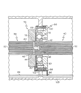
An improved main bearing hub 66 is provided in the present invention in order
to
accommodate a larger main bearing 70. The new bearing hub 66 has a flange 68
with a
larger inner diameter Dm in order to accommodate a main bearing 70 having an
outer race
74 with a larger outer diameter Dg as compared to the outer diameter D6 of the
previous
main bearing 54.
In one embodiment, the inner diameter Dm of flange 68 is about 5.5 inches. The
flange 64 of a prior art hearing hub 62 can be machined to decrease the
thickness of the
flange 64 in order to accommodate a larger main bearing 70. In this way, a new
bearing
hub 66 can be remanufactured from an existing prior art bearing hub 62. In
another
embodiment, a new hub assembly 66 can be created anew in order to meet the
larger
dimensional requirements of the larger bearing 70 of the present invention. In
this case the
6
CA 02820964 2013-07-10
flange 68 of hub 66 could have a larger outer diameter DI I than the outer
diameter 1)I2 of
flange 64 of hub 62. To accommodate the increase in outer diameter DI I, the
diameter of
an existing orifice 100 in a dividing wall 102 of the existing transmission
housing 103
would have to be increased to accommodate the increased diameter Dll. This
could be
accomplished by machining the inner sidewall 101 delimiting the orifice 100.
The inner race 72 of the new bearing 70 can have an inner diameter 1)7 that is
equal
to the inner diameter D5 of the inner race 56 of the previous main bearing 54.
Alternatively, the inner race 72 of the new bearing 70 can have an inner
diameter D7 that
is suitable for placement around a hub 78 that is larger or smaller than the
hub 78 of the
previous splitter ring gear 76. In one improved embodiment, the inner diameter
D7 of the
inner race 72 is about 3.93 inches and the outer diameter Di of the outer race
74 is about
5.51 inches. The splitter ring gear 76 may be replaced or modified in order to
include a
hub 78 that is appropriately sized relative to the inner diameter D7 of the
inner race 72 of
the new main bearing 70. For instance a sleeve can be fitted around the hub
78. It will be
appreciated that the dimensions of the new bearing 70 provided herein are
simply
examples and other suitable dimensions may be employed in various embodiments.
Both
the radial thickness and the axial thickness of the new main bearing 70 may be
increased
relative to the original bearing 54. It will further be appreciated that the
new main bearing
70 may be press fit onto the hub 78 of the splitter ring gear 76 and press fit
into the flange
64 of the bearing hub 62.
The prior art transmission 10 also includes a lubrication line 84 which was
originally used to provide lubrication for a speedometer gear within the
transmission
housing of the prior art transmission. The lubrication line 84 carried
lubrication, such as
oil, from an oil cooler to the speedometer gear. However, the speedometer gear
is
typically no longer used in most transmissions and the lubrication line 84
remains unused.
As illustrated in Fig. 3A, the lubrication line 84 runs past the center
section of the
transmission 10.
In one embodiment of the present invention, the lubrication line 84 is
repurposed
for directing lubrication to the components in the center section of the
transmission such
as the main bearing hub 66, main bearing 70, splitter ring gear 76 and
splitter shaft 40, for
example. In order to repurpose the existing lubrication tube 84, a person of
ordinary skill
in the art only needs to add a threaded connection or tap 86 onto the existing
tube 84.
From this threaded connection 86, the user can then connect a new tube 88 and
run this
7
CA 02820964 2013-07-10
new tube 88 to a desired location adjacent the center section, as demonstrated
in Figs. 3B
and 7. The new tube 88 can include a terminal end having one or more spray
orifices 90
to deliver the lubrication to the directed components. A shutoff valve (not
shown) can
optionally be added downstream of the newly added threaded connection 86 to
divert all
the lubrication to the center section components.
A method for lubricating a center section of the transmission 10 may comprise
the
steps of locating an existing lubrication line 84 that runs adjacent the
center section of the
transmission 10, inserting a threaded connection 86 into the lubrication line
84, attaching a
new tube 88 onto the threaded connection 86, running the new tube 88 to a
location
adjacent components within the center section, and attaching a spray orifice
90 to a
terminal end of the tube 88.
It will be understood that certain features and sub combinations are of
utility and
may be employed without reference to other features and sub combinations. This
is
contemplated by and is within the scope of the claims. Since many possible
embodiments
of the invention may be made without departing from the scope thereof, it is
also to be
understood that all matters herein set forth or shown in the accompanying
drawings are to
be interpreted as illustrative and not limiting. The scope of the claims
should not be
limited by particular embodiments set forthterein, but should be construed in
a manner
consistent with the specification as a whole.
The constructions described above and illustrated in the drawings are
presented by
way of example only and are not intended to limit the concepts and principles
of the
present invention. Thus, there has been shown and described several
embodiments of a
novel invention. As is evident from the foregoing description, certain aspects
of the
present invention are not, limited by the particular details of the examples
illustrated
.. herein, and it is therefore contemplated that other modifications and
applications, or
equivalents thereof, will occur to those skilled in the art. The terms
"having" and
"including" and similar terms as used in the foregoing specification are used
in the sense
of "optional" or "may include" and not as "required". Many changes,
modifications,
variations and other uses and applications of the present construction will,
however,
become apparent to those skilled in the art after considering the
specification and the
accompanying drawings. Al! such changes, modifications, variations and other
uses and
applications which do not depart from the scope of the invention are deemed to
be covered
by the invention which is limited only by the claims which follow.
8