Note: Descriptions are shown in the official language in which they were submitted.
CA 02821448 2013-07-18
TITLE
"STOPE FILL BARRIER"
FIELD OF THE INVENTION
[0001] The present invention relates to a stope fill barrier.
BACKGROUND
[0002] Frequently, valuable minerals are naturally occurring in ore bodies
located in
subterraneous deposits. Due to the location of these deposits, often far
beneath the
surface of the earth and within hard rock, methods of mining to remove them
are
required.
[0003] A modern and presently used method for underground mining entails the
removal
of ore from a panel of rock, known as a stope. The stope is accessible via an
access drive
cut into the earth in the level below the ore body to be mined. The rock and
ore of the
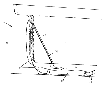
stope are fragmented and removed using explosives and once the area has been
mined, a
stope void remains. This space cannot be left within the ground and, as such,
the void is
backfilled to fill the created underground space.
[0004] Rock must be fragmented by blasting operations to enable its collection
and
removal from a mine. Fragmented rock needs to expand into additional space due
to its
increased volume. Once a stope void has been backfilled, all space has been
removed.
Hence subsequent ore collection operations are delayed by the need for
creating space
blasted rock fragments. Commonly, slot rise holes are drilled up from the
access drive, in
the ore adjacent to the backfilled stope. These holes provide the necessary
space for
expanded rock. Explosives are then used to fragment the rock which enables its
removal.
The drilling of slot rise holes into which blasted rock is allowed to expand
is both costly
and time-consuming.
1
CA 02821448 2013-07-18
[0005] The present invention attempts to overcome at least in part the
aforementioned
disadvantages of previous methods of mining.
SUMMARY OF THE INVENTION
[0006] In accordance with one aspect of the present invention there is
provided a system
for mining comprising the use of a stope fill barrier having a fluid-fillable
bladder for
temporarily filling a portion of a stope void directly adjacent to ore to be
mined and
creating a barrier between the stope void and adjacent ore, wherein the stope
fill barrier is
installed and positioned in the stope void from below the ore.
[0007] The stope fill barrier may be installed and positioned from an access
drive beneath
the ore to be mined.
[0008] The stope fill barrier may be installed and positioned from an access
drive beneath
the ore to be mined and a shaft may be drilled from between an upper surface
of the
access drive and the stope void for the stope fill barrier to be installed
from.
[0009] An end of the shaft at the stope void may be located proximal to a top
of the ore.
[0010] The portion of the stope void filled by the stope fill barrier may be
between 50%
and 100% of a length between a top of the stope void and a lower surface of
the ore.
[0011] The bladder may be filled with fluid subsequent to installation.
[0012] A system according to claim 1, wherein the stope void is backfilled
with the stope
fill barrier installed within the stope void.
[0013] The stope fill barrier may be anchored in place using tensioned ropes
or cables
fixed to anchor points below the ore.
2
CA 02821448 2013-07-18
[0014] The finable bladder may be in connection with at least one pressure
regulator to
maintain pressure of the fluid-filled bladder.
[0015] The fluid-filled bladder may be capable of holding fluid pressures of
between
0.5psi and 50psi.
[0016] The bladder may be made from a hard-wearing, heavy duty, puncture
resistant
material.
[0017] The bladder may comprise a plurality of bladders contained within an
outer bag.
[0018] The bladder may be arranged to be inflated with air.
BRIEF DESCRIPTION OF DRAWINGS
[0019] The present invention will now be described, by way of example, with
reference
to the accompanying drawings, in which:
Figure 1 is a perspective view of a system for using a stope fill barrier
according
to a preferred embodiment of the present invention in an installed, filled
position;
Figure 2 is a perspective view of the system of Figure 1 in an un-installed,
unfilled position; and
Figure 3 is a perspective, partly cut away view of the bladder of a stope fill
barrier
according to a preferred embodiment of the present invention connected with a
schematic
view of a filling means.
DESCRIPTION OF THE PREFERRED EMBODIMENT
[0020] Referring to Figures 1 and 2, there is shown a system for temporarily
filling a
vertical part of a stope void 28 directly adjacent to ore to subsequently be
mined, or stope
30, comprising the use of a stope fill barrier 10 comprising a fillable
bladder 12 for filling
part of the stope void 28 and creating a barrier between the void 28 and
adjacent ore 30,
wherein the stope fill barrier 10 is installed and positioned in the stope
void 28 from
below the stope 30, such as from an access drive 34, in accordance with the
present
3
CA 02821448 2013-07-18
=
invention.
[0021] The stope fill barrier 10 comprises a connection 22 adapted for
coupling with
fluid lines 24 connected to a filling means 36. The stope fill barrier 10
further comprises
ropes or cables 18 which, in use, facilitate the installation and positioning
of the stope fill
barrier 10. In accordance with a preferred embodiment of the present
invention, at least
two ropes or cables 18 may be connected with a lower end of the bladder 12 and
at least
two ropes or cables may be connected with an upper end of the bladder 12.
[0022] In accordance with the system of the present invention, anchor points
20, for
example eye bolts, are provided on the access drive 34. In a preferred
embodiment, at
least two anchor points 20 are provided respectively on an upper surface and a
lower
surface of the access drive 34. At least one access shaft 32 is provided
between the
access drive 34 and the stope void 28. Preferably, the access shaft 32 is
drilled from
below in a diagonal from the upper surface of the access drive 34 remote from
the stope
void 28 to the stope void at an upper region of the next stope 30.
[0023] With reference to Figure 3, in accordance with a preferred embodiment
of the
present invention, the finable bladder 12 comprises a plurality of inner
bladders 14. The
inner bladders 14 are contained within an outer bag 16. The outer bag 16 is
preferably
made from a wear and scuff-resistant material. More preferably, the outer bag
16 is made
from a hard-wearing, heavy duty material.
[0024] Cable attachment points 26 are provided on the outer bag 16 of the
bladder 12. In
accordance with a preferred embodiment, the cable attachment points 26 are
provided as
loop handles. Preferably, the attachment points 26 are spaced at intervals
between 100
millimetres (mm) and 1 metre (m), more preferably at about 500mm intervals on
both
sides of one face of the bladder 12. The attachments points 26 are provided
for a length
of between lm and 10m, preferably about a 5m length at both an upper and lower
end of
the bladder 12.
4
CA 02821448 2013-07-18
=
[0025] In accordance with an additional embodiment of the present invention,
the cable
attachment points 26 may be provided as a continuous line, for example, a
steel cable.
The steel cable may be sewn or otherwise suitably attached to the fabric of
the outer bag
16. The steel cable then allows for anchoring of additional ropes or cables 18
at varying
points along the length of the bladder 12 thereby serving as cable attachment
points 26.
[0026] Each inner bladder 14 comprises a connection 22 to facilitate coupling
with the
fluid lines 24 to enable filling of the inner bladders 14. In a preferred
embodiment, the
inner bladders 14 are capable of holding fluid pressures between 0.5psi and
50psi,
preferably between 1 Opsi and 30psi. Reinforcement banding 44 is provided on
the inner
bladders 14 which may allow for even filling of the inner bladders 14.
[0027] The fluid lines 24 connect with pressure regulators 38. Preferably, one
pressure
regulator is provided for each one fluid line 24 for each inner bladder 14. In
use, the
pressure regulators 38 maintain the requisite pressure of each of the inner
bladders 14. At
least one hose 42 is connected with the pressure regulators 38 through a
coupling 40.
Fluid for filling the inner bladders 14 is provided through the hose 42.
[0028] In use, an ore body to be mined, or stope 30, is provided underground.
Using
methods and techniques known in the art, an access drive 34 is provided
beneath the
stope 30. A stope void 28 is present adjacent to the stope 30 from previous
mining
activities.
[0029] In order to access the stope void for installation of the stope fill
barrier 10, at least
one access shaft 32 is drilled from the upper surface of the access drive 34,
through the
stope 30 to break through to the stope void 28 near the top of the stope 30.
The shaft 32
may be drilled from below by a typical longhole drill and may be variable in
diameter,
preferably from 64mm to 150mm.
[0030] Ropes or cables 18 are placed within the access drive 34 end of the
shaft 32 and
are made to travel to the stope void 28 end of the shaft 32. The ropes or
cables 18 are
CA 02821448 2013-07-18
fed, lifted or pushed through the shaft 32 in any manner suitable for moving
them to the
required position.
[0031] The ropes or cables 18 are fed through the shaft 32 and allowed to fall
from the
stope 30 until they are within reach of the level of the access drive 34. The
ropes or
cables 18 are then retrieved from their position within stope void 28 to be
pulled into the
access drive 34. In a preferred embodiment, the ropes or cables 18 are
retrieved using a
pole and hook arrangement, operable from within the access drive 34. The pole
is used to
reach the ropes or cables 18 and the hook used to grab them. In another
embodiment, the
ropes or cables may be accessed using a vehicle driven into the stope void 28
to retrive
the ropes or cables 18 and transport them to the access drive 34. The vehicle
may be
remotely operable.
[0032] The stope fill barrier 10 of the present invention is provided in the
access drive 34
in preparation for installation. The ends of the ropes or cables 18 which have
travelled
through the shaft 32 are then attached to the stope fill barrier 10 in
accordance with the
present invention. Attachment points 26 are utilised for connection with the
ropes or
cables 18. The selection of suitable attachment points 26 is made for a
resultant desired
height of the bladder 12 relative to the end of the shaft 32 within the stope
void 28. For
example, if it is desired to have the top of the bladder 12 at the same height
as that of the
end of the shaft 32 in the stope void 28, then an attachment point 26 at the
upper end of
the bladder 12 would be used. If it is desired to have the top of the bladder
12 two metres
higher than the end of the shaft 32 in the stope void 28, then an attachment
point 26 two
metres below the top of the bladder 12 would be utilised for connection with
the ropes or
cables 18.
[0033] Following connection of the ropes or cables 18 to the stope fill
barrier 10, the
bladder 12 is hoisted into position in the stope void 28 adjacent the stope
30. Any
suitable method may be used for hoisting, such as manually or using a
mechanical winch
or pulling with a vehicle.
6
CA 02821448 2013-07-18
=
=
[0034] A further at least two ropes or cables 18 are attached to the lower end
of the
bladder 12. The at least two ropes or cables 18 at both the upper and lower
ends of the
bladder 12 are tensioned so that the bladder 12 is positioned firmly and
restrained in a
desired location between the stope void 28 and the adjacent stope 30. The
ropes or cables
18 are tensioned with any suitable tensioning device or method and anchored to
the
anchor points 20. The lower end of the bladder 12 may be level with, above or
below the
level of the upper surface of the access drive 34.
[0035] Once the bladder 12 is in position and anchored, one end of each fluid
line 24 may
be coupled with a respective connection 22 on the inner bladders 14. A second
end of
each fluid line 24 may be connected with the corresponding pressure regulator
38, which
is, in turn, connected with a hose 42 through a coupler 40. Fluid, for example
mine air, is
then brought from the hose through to fill the inner bladders 14 up to and
kept at a
required pressure by the pressure regulators 38.
[0036] With the stope fill barrier 10 in place to temporarily fill a portion
of the stope void
28, the remainder of the stope void 28 may be backfilled according to normal
and known
methods. In a preferred embodiment, the portion of the stope void 28 filled by
the stope
fill barrier 10 is between about 50% and 100%, more preferably about 75% to
95% of the
length between a top of the stope void 28 and an upper surface of the access
drive 34.
[0037] After the filled stope void 28 has cured, the stope fill barrier 10 is
preferably
emptied and disconnected from the fluid lines 24 and filling means. The ropes
or cables
18 may be removed from the anchor points 20 and the stope fill barrier
uninstalled. In a
second embodiment, the stope fill barrier 10 may remain in the backfill or be
destroyed
by subsequent blasting and mining operations.
[0038] The created space, from which the stope fill barrier 10 has been
uninstalled,
provides a relief void for subsequent blasting operations or removes the need
for holes to
be drilled in the next ore stope 30 and subsequent mining can commence
immediately.
7
CA 02821448 2013-07-18
=
=
[0039] Modifications and variations as would be apparent to a skilled
addressee are
deemed to be within the scope of the present invention.
8