Note: Descriptions are shown in the official language in which they were submitted.
CA 02821820 2013-07-03
"Pressure sewer control system and method"
Technical Field
Described embodiments generally relate to pressure sewer systems and the
monitoring
and control of such systems for components, such as pumps, in such systems.
Some
embodiments specifically relate to pump control systems for pressure sewer
installations, while other embodiments relate to systems for monitoring a
network of
pressure sewer installations including such pump control systems.
Further
embodiments relate to pressure sewer installations or kits therefor that
include the
pump control systems.
Background
Pressure sewer systems involve the use of a fluid reservoir, such as a tank,
buried in the
ground to receive sewerage from a dwelling or building. Such pressure sewer
systems
rely on a pump within the fluid reservoir to pump fluid out of the reservoir
and into a
reticulated sewer system comprising fluid conduits to transport the sewerage
to a
suitable processing station. Such pressure sewer systems are generally
installed in
locations where gravity cannot be adequately relied on as the impetus for
transporting
the waste fluid within the sewer network.
The pressure sewer systems rely on proper functioning of the pump in
combination
with a float switch to avoid the fluid reservoir becoming too full and
overflowing.
Where the pump does not operate properly to evacuate the waste fluid from the
fluid
reservoir, this can lead to an undesirable overflow and/or leakage of sewerage
from the
fluid reservoir. This overflow can be a very unpleasant experience for the
inhabitants
of the dwelling and such inhabitants will commonly contact the organisation
responsible for maintenance of the sewer system in order to rectify the
problem. In
such situations, because the organisation responsible for maintenance of the
sewerage
system learns about the malfunction from the complainants, there can be a
delay before
appropriate personnel can be dispatched to address the problem and before an
appropriate solution is implemented. Not only do such situations result in
significant
dissatisfaction on the part of the inhabitants that the pressure sewer system
is intended
to serve, the leakage of the system presents possible public health and safety
issues and
reflects badly on the organisation responsible for the system's maintenance
and proper
function.
CA 02821820 2013-07-03
2
It is desired to address or ameliorate one or more shortcomings of prior
pressure sewer
systems, or to at least provide a useful alternative thereto.
Throughout this specification the word "comprise", or variations such as
"comprises" or
"comprising", will be understood to imply the inclusion of a stated element,
integer or
step, or group of elements, integers or steps, but not the exclusion of any
other element,
integer or step, or group of elements, integers or steps.
Any discussion of documents, acts, materials, devices, articles or the like
which has
been included in the present specification is not to be taken as an admission
that any or
all of these matters form part of the prior art base or were common general
knowledge
in the field relevant to the present disclosure as it existed before the
priority date of
each claim of this application.
Summary
Some embodiments relate to a pump control system for a pressure sewer
installation,
the system comprising:
a controller arranged to control supply of power to a pump of the pressure
sewer
installation, wherein the controller is arranged to receive an output signal
from a sensor
in a fluid reservoir of the pressure sewer installation, the output signal
being indicative
of a measured fluid level in the fluid reservoir;
a memory accessible to the controller and arranged to store operation
information pertaining to operation of the pressure sewer installation; and
a wireless transceiver in communication with the controller to allow the
controller to communicate with a remote server over a communications network.
The controller may be configured to control and monitor operation of the
pressure
sewer installation and to send stored operation information to the remote
server. The
operation information may include measured fluid level information.
The controller may be configured to compare the fluid level to a fluid level
threshold
stored in the memory of the controller and to cause the pump to operate to
pump fluid
out of the fluid reservoir when the fluid level is greater than or equal to
the fluid level
threshold.
CA 02821820 2013-07-03
3
The controller may be responsive to a command received from the remote server
to
store a changed fluid level threshold in the memory.
The wireless transceiver may be configured to communicate with the remote
server
using a mobile telephony standard protocol. The controller may be configured
to be
controllable remotely by commands received from the remote server.
The system may further comprise one or more additional devices and one or more
additional wireless or wired transceivers or receivers in communication with
the
controller, to allow the controller to communicate with or receive information
from the
one or more additional devices.
The one or more additional devices may be flow meters or other instruments for
the
monitoring of a sewerage or water supply network.
The system may be mains powered and may comprise a backup power supply to
power
the controller and the wireless transceiver in the absence of adequate mains
power.
The controller may be further configured to receive a float switch output
signal from a
float switch in the fluid reservoir indicative of a high fluid level, the
controller being
configured to operate the pump in response to the fluid switch output signal.
Some embodiments relate to a pressure sewer network monitoring system,
comprising:
a plurality of the described pump control systems; and
the remote server in communication with the wireless transceiver of each of
the
pump control systems;
wherein the remote server is configured to monitor operation of each pressure
sewer installation based on messages received from each pump control system
and to
affect operation of each pump control system by transmission of one or more
commands from the remote server to each pump control system.
The system may further comprise a computerised user interface in communication
with
the remote server to allow remote user control of each pump control system.
The system remote server may be configured to determine an alarm condition
based on
the messages received and to automatically transmit one or more alarm messages
to one
. CA 02821820 2013-07-03
=
4
or more user recipients, the one or more alarm messages including an
indication of the
alarm condition.
Some embodiments relate to a pressure sewer installation, comprising the
described
pump control system and further comprising the pump, the sensor and the fluid
reservoir.
Some embodiments relate to a kit for a pressure sewer installation, the kit
comprising
the described pump control system and further comprising the pump, the sensor
and the
fluid reservoir.
Brief description of the drawings
Embodiments are described in further detail below, by way of example, with
reference
to the accompanying drawings, in which:
Figure 1 is a schematic representation of a pressure sewer installation having
a pump
control system according to some embodiments;
Figure 2 is a schematic diagram of the pump control system;
Figure 3 is an electrical circuit schematic diagram of the pump control
system;
Figure 4 is a schematic diagram of a pressure sewer network monitoring system
according to some embodiments;
Figure 5 is an example user interface display generated by interface
components of the
pressure sewer network monitoring system;
Figure 6 is an example plot of fluid level in a fluid reservoir of one
pressure sewer
installation over time.
Figure 7 is a further example user interface display generated by interface
components
of the pressure sewer network monitoring system;
Figure 8 is a further example user interface display generated by interface
components
of the pressure sewer network monitoring system; and
CA 02821820 2013-07-03
Figures 9A and 9B are example reports of measured fluid levels in multiple
installations in different zones.
5 Detailed description
Described embodiments generally relate to pressure sewer systems and the
monitoring
and control of such systems or components, such as pumps, in such systems.
Some
embodiments specifically relate to pump control systems for pressure sewer
installations, while other embodiments relate to systems for monitoring a
network of
pressure sewer installations containing described pump control systems.
Further
embodiments relate to pressure sewer installations or kits therefor that
include the
pump control systems.
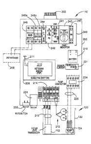
Referring in particular to Figures 1, 2 and 3, there is shown a pressure sewer
installation 100 comprising a pump control system 110 operating in cooperation
with a
buried sewerage tank 120. The pump control system 110 constitutes the above-
ground
part of installation 100 while the sewerage tank 120 constitutes the in-ground
part. The
sewerage tank 120 has a fluid reservoir 122 that is arranged to receive waste
water from
a domicile or other building 102 via an inlet conduit 126. The fluid reservoir
122
houses a pump 124 therein, with the pump 124 being arranged to pump fluid out
of the
reservoir 122 via a fluid outlet conduit 128 into a reticulated sewerage
network of fluid
conduits.
The in-ground components of installation 100 also include a level sensor 112
and a
float switch 212. The level sensor 112 may be a pressure transducer, for
example, and
is in electrical communication with the pump control system 110 via suitable
means,
such as an electrical cable. The pump 124 operates under the control of pump
control
system 110, only turning on and off in response to the action of a suitable
pump
contactor (relay) 224 that supplies mains power to the pump 124 from a mains
power
supply 248.
The level sensor 112 may be arranged to have the sensing head generally
submerged
below the fluid level in order to obtain a constant accurate measure of the
fluid level
within the fluid reservoir 122 and provide a constant (or sufficiently regular
as to be
effectively constant) output signal to the pump control system 110. Float
switch 212 is
CA 02821820 2013-07-03
6
provided as a high level fail safe, so that when the fluid level in the
reservoir 122 gets
above the shut-off level of the float switch 212, the float switch 212
provides a fluid
level high signal to pump control system 110, which causes pump 124 to begin
pumping fluid out of the reservoir 122 (if it was not already doing so).
Pump control system 110 is the above-ground part of installation 100 and may
be
located on a wall or other position for easy access by inhabitants of the
domicile 102 or
maintenance personnel. Pump control system 110 has a housing 202 that is
closed and
locked against persons other than authorised personnel. The housing 202 has a
visual
alarm indicator 203 and an audible alarm 204 to indicate to the inhabitants
that a fault
has occurred or is occurring. A mute button 205 may be located on an external
part of
the housing 202 and may be actuated in order to silence the audible alarm 204.
Pump control system 110 has a controller 208, a wireless transceiver unit 210,
a backup
power supply, for example in the form of a battery 215, a relay 224 to control
operation
of the pump 124 and an electrical supply and control block 240. Pump control
system
110 may also have one or more additional wireless or wired transceivers or
receivers
(not shown). One or more flow meters and/or other instruments (not shown)
associated
with water, power or other utilities may also form part of system 100 and be
in
communication with the one or more additional wireless or wired transceivers
or
receivers. Controller 208 comprises a memory (not shown) and at least one
processor
(not shown) configured to execute program instructions stored in the memory.
Also
stored in the memory are a number of set points and control parameters for
operation of
the pump and the wireless transceiver unit 210.
Controller 208 is enabled for two-way communication via transceiver unit 210
with a
remote server 130 over wireless telecommunications infrastructure, for example
using a
standard GSM mobile telephony protocol. Controller 208 may also be enabled for
one-
or two-way communication with external devices, such as flow meters or other
instruments (not shown), via additional transceiver or receiver units (if
present) over a
low power wireless communication protocol, for example Bluetooth or IEEE
802.11
protocols, or a wired communication protocol. In this way, the controller and
transceivers/receivers may act as a fully or partly wireless hub to allow
communication
and/or control of multiple local instruments or devices associated with system
100. The
transceiver unit 210 has a transmitting and receiving antenna 211 concealed
within the
CA 02821820 2013-07-03
7
housing 202. The housing 202 is formed of a suitable non-conductive material
to allow
sufficient signal transmission strength out of and in to the housing 202.
Controller 208 stores in its memory measured fluid level data when it changes
by a
predetermined amount, such as a percentage amount or a number of millimetres,
for
example. Similarly, other measured parameters or operational statuses are
recorded in
the controller's memory when they change and time-stamped as of when they
occur.
This stored data is then uploaded via the transceiver unit 210 to the server
130
periodically, such as every 1, 2, 4, 6, 8, 12 or 24 hours, or on demand from
the server
130.
The schematic layout and electrical diagrams are shown in Figures 2 and 3 for
the
pump control system 110. These two drawings should be read in conjunction with
each
other in order to understand the physical and electrical layout of the
components of
pump control system 110.
Battery 215 provides a backup power source for the controller 208 and
transceiver unit
210 in order to maintain communications capabilities during a loss or
substantial drop
in power level received from mains power supply 248. A current sensor 221 and
voltage sensing relay 241 are coupled to the mains power supply 248 via a
mains
switch 246 in order to sense the input current and voltage. The current sensor
221 and
voltage sensing relay 241 provide their outputs to controller 208 so that the
controller
208 can monitor the input power supply level and cease operation of the pump
124, if
necessary. The power supply input block 240 also comprises first and second
circuit
breakers 245a, 245b and a DC power supply transformer 242. A fuse 244 is also
provided, in case of spikes in the mains supply. The DC power supply 242
charges the
battery 215. A 12 VDC control relay 247 is provided to allow the controller
208 to
control the pump relay 224.
The pump relay 224 is operated in response to control signals from controller
208 when
a manual switch is in the auto position. When the manual switch 243 is in the
off
position, the relay 224 is open and the pump 124 does not receive power. When
the
manual switch 243 is in the manual position, the relay 224 is closed and the
pump
receives mains power independently of control from the controller 208. The
relay 224
provides mains power to the pump 124 via suitable power cables 225 that extend
into
the ground and into the fluid reservoir 122 in a suitable manner.
= CA 02821820 2013-07-03
8
Fluid level transducer 112 has its output conductors 213 coupled to a
connection block
214 to which the controller 208 is electrically connected. Also coupled to
this
connection block 214 is the output of the float switch 212, so that the
controller 208
receives an on or off status signal from the float switch 212.
Controller 208 may include or be in the form of a serial communication and
data
acquisition (SCADA) unit, which effectively functions as a programmable logic
controller (PLC). The controller 208 has a suitable serial data connection
with
transceiver unit 210. The controller 208 may be or include a suitable DNP3
SCADA
pack 100 controller from Control Microsystems, for example. Other controllers
may be
used in the system 100 and may employ the DNP3 communications protocol or
another
suitable communications protocol to perform the functions of controller 208
described
herein.
The transceiver unit 210 may be a NetComm NTC-6908 industrial 3G cellular
network
router, for example. The transceiver unit 210 may thus provide a point-to-
point or
point-to-multi-point communication capability in order to suitably interface
with
remote server 130. The transceiver unit 120 may use a suitable domain name
system
(DNS) capability so that any subscriber identity module (SIM) in the
transceiver unit
120 can be interchanged with another such SIM.
The digital and analogue inputs and outputs for the controller 208 are
generally as
follows:
Controller Binary Inputs:
BI-1: Emergency High Level Float Switch;
BI-2 Site Mains Power Failed Alarm;
BI-3: Pump Run Command State.
Controller Binary Outputs:
B0-1: Pump Inhibit signal from controller 208.
Controller Analogue Inputs:
AI-1: Well Level from level sensor 112;
AI-2: Pump Current;
= CA 02821820 2013-07-03
9
AI-3: Pump Start Level SP (status);
AI-3: Pump Stop Level SP (status).
Controller Analogue Outputs:
A0-1: Pump Start Level SP (from server 130);
A0-2: Pump Stop Level SP (from server 130).
The operation of the controller 208 may be further characterised in the
following terms:
Operation
The pump 124 runs if the sensed level of fluid in the tank 122 is at or above
the Pump
Start Level set-point and stops if the sensed fluid level in the tank 122
reaches or falls
below the Pump Stop Level set-point. The Pump Start Level set-point (A0-1) and
the
Pump Stop Level set-point (A0-2) are not physical outputs of controller 208 ¨
rather,
they are both set using a software configuration tool 430 executing on (or
served by)
the server 130 and accessible to authorised users via a suitable computerised
user
interface hosted by server 130. The user interface experienced by users of
client
devices 420, 425 may be provided by a browser application 440 executing on one
or
more of the client computing devices 420, 425 in system 400, for example. Once
selected, the Pump Start Level set-point and the Pump Stop Level set-point are
stored
in data store 140 and transmitted by server 130 to the transceiver unit 210
and
controller 208 of each installation 100 to which the selected set-points
apply.
A high level analogue set point may also be included in order to start the
pump 124 and
set alarms if the sensed fluid level is at a point above a normal start level.
If the
Float/Emergency High Level signal (BI-1) is active, then the pump 124 will be
forced
to run until the signal input goes low for a pre-set time (set via the user
interface
accessible via client computing devices 420, 425). The controller 208 can
disable the
pump 124 for a set time (default 8 hours).
Controller 208 may be receive and respond to a command from the configuration
tool
430 to adjust the Start Level set-point to run the pump 124 between the Start
Level set-
point and Hi Level set-point until a specified time (in a flush mode), so that
a greater-
than-normal fluid volume may be flushed from the reservoir 120.
Digital Inputs
CA 02821820 2013-07-03
Float/Emergency High Level
Power Status OK (from voltage monitor relay)
High Pressure input
Alarm Mute Push Button
5
Analogue inputs
Level Probe (4-20 ma)
Pump Amps ¨CT (4-20 ma)
10 Digital Outputs
Motor Run (to motor contactor)
Alarm Horn (Horn to auto mute after 5 min)
Alarm Lamp (different flash depending on alarm)
Strobe flasher (on until alarms clear)
SCADA Display (provided by user interface on client devices 420, 425)
Pump Runs
Pump Fails
Pump Running Current
Level
All alarms
All Set points
Force off Time set-point
Alarms (alarms clear on PLC power cycle ¨ or condition cleared)
Lamp Action Alarm
Lamp double flash Pump Failure
If a high current is detected for a set time period, stop the pump for 10 min.
If a pump
stops 10 times (or another configurable number) in a row, lock out the pump.
The pump
alarm continues to operate.
Lamp Action Alarm
Lamp triple flash Pump High Pressure
= CA 02821820 2013-07-03
11
If a high pressure is detected for a set time, stop the pump for 10 min. If a
pump stops
times in a row, lock out the pump.
Lamp Action Alarm
5 Lamp on Emergency High Level
On detection of a high float condition tripping the float switch, activate the
Lamp/Horn
and notify the server 130, which displays the condition via the user interface
430.
10 Generally, the lamp strobe and horn activate after a pre-set time delay
from the alarm
occurrence and an exception report is sent to the remote server 130 after a
separate
(shorter) time value. The time difference between the strobe and horn
activation and the
exception report transmission may be up to 18 hours. This allows remote
diagnostics to
be run and allows the responsible utility organisation time to assess and
rectify the
apparent problem before the resident is notified of the problem by activation
of the
alarm.
Set points
Pump Stop Level
Pump Start Level
Pump High Level
Pump High Amps
Pump No run/Low Amps
Pump Run to Long Time
Pump Emergency High Level Run on timer
Pump Disable timer
Referring now to Figure 4, a pressure sewer monitoring system 400 comprising
multiple installations 100 is described in further detail. Pressure sewer
monitoring
system 400 comprises multiple installations 100 located in different
geographic
locations across one or more sewerage network zones. The multiple
installations 100
may be part of a single zone within a larger sewerage network or may be spread
across
different zones and/or different networks. By way of example only, each zone
may
have one, two, three, four, five, six, seven, eight, nine, ten or more
installations 100
located at different positions within the zone. Further, there may be more
than ten, for
example between ten and possibly hundreds of such installations 100 within a
CA 02821820 2013-07-03
12
particular sewerage zone and/or network. By way of example, Figure 8
illustrates six
separate zones (indicated by references 812a, 812b, 812c, 812d, 812e and
812f),
located within part of a larger service zone 810 and viewable in relation to a
map
display 800 on a client device. Each zone 812 has one or more installations
100 located
therein.
Fluid monitoring system 400 further comprises one or more servers or server
systems,
referred to herein for convenience as server 130, at least one wired client
device 420
and/or at least one mobile client device 425 and a data store 140. Server 130
is
arranged to receive data from installations 100 representative of the sensed
conditions
of the pump 124 and/or fluid level in the fluid reservoir 122 at various
different
locations. This data is received over a data network comprising suitable
communications infrastructure (not shown) that is at least partially wireless,
such as a
cellular network. For example, the transceiver units 210 of installations 100
may be
configured to transmit data to server 130 using the GSM or GPRS/3G standards
for
mobile telephony or their technological successors. Alternatively, lower
power, shorter
distance wireless communication techniques may be employed, for example where
a
local wireless data hub is in sufficient proximity to support wireless
communication
with the transceiver unit 210 within a nearby installation 100. In some
embodiments,
the transceiver unit 210 may act as a local wireless data hub for other
devices, such as
metering or sensing instruments, in the immediate vicinity of system 100.
Server 130 processes the data received from transceiver units 210 and stores
it in data
store 140 for subsequent retrieval as needed. Data store 140 may comprise any
suitable
data store, such as a local, external, distributed or discrete database. If
the data
received at server 130 from installations 100 indicates an alarm condition in
any one or
more of installations 100, server 130 accesses data store 140 to determine a
pre-
determined appropriate action to be taken in relation to the specific alarm
condition,
and then takes the appropriate action. The action to be taken may vary,
depending on
the installation 100, for example where some installations 100 may play a more
critical
monitoring role than others. Such actions may include, for example, sending
one or
more notifications, for example in the form of text messages and/or emails, to
one or
more of client devices 420, 425.
Regardless of whether an alarm condition is indicated by the data received at
server
130 from installations 100, that data is processed and stored in data store
140 for later
= CA 02821820 2013-07-03
13
retrieval by a server process and/or at a request from a client device 420,
425. For
example, server 130 may execute processes (based on program code stored in
data store
140 or a memory local to the server 130, for example), to perform trending and
reporting functions to one or more client devices 420, 425. For example,
server 130
may provide to a client device 420 information to enable generation of a
display 500,
600, 700 or 800 (Figures 5, 6, 7 or 8 respectively) via browser application
440 at client
device 420 or 425 in response to a request for such information or
automatically at
regular intervals. Display 500 may chart historical and current data for one
or more
conditions of operation of the pressure server installations 100 at different
locations
over a period of time. For example, as shown in Figure 5, display 500 may
include a
chart 540 of fluid levels at a particular pressure sewer installation 100 over
a period of
time, as well as displaying status information 530 for a number of operational
parameters of the installation 100.
Server 130 executes a user interface 430 based on locally accessible stored
program
code to allow users of client devices 420, 425 to access configuration,
control,
monitoring and reporting functions of server 130 with respect to installations
100. The
user interface 430 thus acts as a control and configuration tool accessible to
users of
client devices 420, 425. The user interface, control and configuration
functions of user
interface 430 are primarily performed by server 130, but some functions may be
executed in part by the browser application 440 on client devices 420, 425
based on
code, including applets for example, served to the respective client devices
420, 425
from server 130.
In alternative embodiments, instead of browser application 440, each client
device 420,
425 may execute a specialised software application stored in local memory
accessible
to the processor of the device. This specialised application may perform
various user
interface functions locally and communicate with the server 130 as necessary.
For
example, for mobile client computing devices 425, the specialised application
may be
in the form of a "smart phone" application.
Displays 500, 600, 700 and 800 shown in Figures 5, 6, 7 and 8, respectively,
may be
generated at client device 420, 425 by a suitable software application
executing on the
client device 420, 425, such as browser application 440 when executed by a
processor
of the client device 420, 425 according to program code stored in the local
storage
accessible to that processor.
= CA 02821820 2013-07-03
14
In preferred embodiments, transceiver unit 120 is enabled for bidirectional
communication with server 130, so that new fluid level thresholds can be set,
control
commands can be issued, firmware updates can be received and/or diagnostic
monitoring and testing can be performed remotely.
Pressure sewer monitoring system 400 thus comprises a series of installations
100
located around an area or zone for which operational status is desired to be
monitored.
These installations 100 communicate with server 130, which in turn
communicates
with client devices 420, 425 as necessary. Server 130 also tracks and stores
historical
data received from the installations 100 and processes the incoming and
historical data
according to rules stored in data store 140 to determine whether certain pre-
defined
events of interest may be occurring. Such events may be complex events and may
be
defined in the stored rules as such. In order to optimally manage a particular
sewerage
zone or zones, for example in flood situations system 400 may control
installations 100
to cease normal autonomous operation for a period of time or to operate under
a higher
level set-point.
In system 400, each installation 100 may be configured to have the same or a
similar
set of operational parameters (i.e. alarm levels, sensor sampling times,
reporting
intervals, etc.) and may have the same set of sensors 112, 212 and general
configuration.
In some embodiments of system 400, the transceiver unit 210 of each
installation may
be configured to send a message directly to a mobile communication device of
an end
user (i.e. client device 420, 425) when an alarm condition is determined by
controller
208. This may be instead of or in addition to sending the message to the
server 130.
Advantages of the described embodiments over prior pressure sewer systems
include a
substantially improved remote control and monitoring capability. This is
further
supported by use of a mobile telephony standard protocol to facilitate point-
to-point or
point-to-multi-point communication between the server 130 and the controller
208 of
each pump control system 110. There are also substantial advantages in
providing the
level sensor output from each level sensor 112 to the remote server 130 on a
regular
basis, to allow monitoring and optimised usage of sewage network
infrastructure when
a number of installations 100 are monitored and controlled separately or
together as
CA 02821820 2013-07-03
part of the same pressure sewer system 400. For example, usage histograms,
such as
those illustrated in Figures 9A and 9B can be obtained for different zones.
The described embodiments allow calculation of real time waste fluid volumes,
which
5 provides accurate engineering data for planning and design purposes.
Described
embodiments also allow real time calculated waste fluid flow monitoring, which
can be
used with remote control of the pumps 124 by commands from server 130 to
manage
peak flows discharged into sewer mains and treatment facilities. This can more
evenly
distribute the waste fluid flows over time, which can ease the burden on the
processing
10 infrastructure and reduce the risk of breakdown of the infrastructure.
Further advantages associated with described embodiments include the ability
to infer
the likelihood of leakage from one or more installations 100. For example, for
a given
installation, 100, the number of level changes during a particular period,
such as the
15 time between 2.00 a.m. and 3.00 a.m., together with a measure of the
amount of level
change over time (such as millimetres per minute) can indicate the likelihood
of a leak
at the site of the installation 100. A steady rise in the fluid level during
that period over
a number of days can indicate a small leak. Maintenance personnel can
therefore be
dispatched to the site to investigate before the leakage becomes a significant
problem.
The described embodiments therefore allow organisations, such as those
responsible for
maintenance of the pressure sewer network, to identify and address problems
with one
or more installations 100 before they develop into a complaint by the
inhabitant of the
domicile 102.
Referring in particular to Figure 5, the system 400 comprises capabilities,
including
suitable software and hardware modules, to execute user interface 430, which
allows
operational maintenance personnel to monitor and remotely control the
operation of
each installation 100. Display 500 in Figure 5 is an example of a user
interface display
generated by browser application 440 based on program code and/or data served
from
server 130. Display 500 has a graphical depiction 510 of the fluid reservoir
122 of a
particular installation named LPS00013. Also shown in the graphical
representation
510 is the pump 124, together with an indication of the upper fluid level
threshold or
set-point (for example, 400 mm) at which the pump 124 will be operated in
order to
pump fluid from the fluid reservoir 122. That upper fluid level threshold may
be
reconfigured using the user interface 430 and suitable software control
actions, for
example selected from the control options list 520 presented via browser
application
= CA 02821820 2013-07-03
16
440. Similarly, a lower level threshold, shown in this case as 100 mm, may be
the level
at which the pump 124 is caused to stop running. The control options list 520
may
allow the operational personnel to remotely take control or release control of
the pump
124 by issuing commands to the associated controller 208. Further, status
information
is provided in a status display 530 of the user interface. This status
information may be
reconfigured where permissible, for example in order to change an operational
mode of
the pump or change one or more of the set points.
Display 500 in Figure 5 also has a sub-display 540 of a fluid level plot over
time,
indicating the increasing fluid level up to the point where it reaches the
upper fluid
level threshold, after which the pump decreases the fluid level in a short
period back
down to the minimum (lower level threshold). This plot 540 can also indicate
the
current drawn by the pump 124 over time, in order to verify that the high
current
consumption periods of the pump 124 correlate with the decreases in the fluid
level due
to pump operation. This plot 540 is shown in further (magnified) detail in
Figure 6.
Figure 7 illustrates a further display 700 of the user interface, including a
list 710 of
multiple sites of installations 100, from which a particular installation 100
of interest
may be selected for further detailed analysis or control. In the user
interface illustrated
in Figure 7, certain selectable control functions 720 are illustrated. For
example, the
operational personnel can force the immediate data polling by server 130 of
the
controller 208 of a particular installation 100 (rather than wait the normal
24 hour
polling period), in order to have that controller 208 upload all of the
recorded data
accumulated and stored in its memory since the last upload. Further,
selectable options
are provided to inhibit operation of the pump 124 or the pump control
functions of the
controller 208. Further, the user interface (presented via browser application
440)
shown in Figure 7 allows new installations to be added to the live network
from a list
732 as they become installed. Additionally, a list 740 of sites at which
installation is
pending may be provided. Control buttons 735 are provided to allow editing of
the list
732 and control buttons 745 are provided to allow editing of the list 740.
Further
reports and displays may be selectable, such as the ability to view the
history of all
power failures of the installations 100.
As is evident from the user interface shown in Figure 7, the server 130
maintains
comprehensive data records of each installation 100 in the data store 140,
together with
historical operational data for each such installation. The length of time of
the
. CA 02821820 2013-07-03
17
historical data may be configured depending on how much data storage is
available
and/or how much historical data is deemed to be useful in accomplishing the
necessary
monitoring and control functions. The stored historical data may be
periodically
condensed, as necessary, in order to avoid storing historically irrelevant
information.
Embodiments have been described herein by way of example, with reference to
various
possible features and functions. Such embodiments are intended to be
illustrative
rather than restrictive. It should be understood that embodiments include
various
combinations and sub-combinations of features described herein, even if such
features
are not explicitly described in such a combination or sub-combination.