Note: Descriptions are shown in the official language in which they were submitted.
CA 02821997 2013-06-17
HOT RUNNER NOZZLE
[0001] The invention relates to a hot runner nozzle for injection molding
tools with a
nozzle body having a passage channel for a melt, the nozzle body comprising a
feed
opening at a first end region and an outlet opening at a second end region.
[0002] In one hot runner nozzle of this type known from OE 10 2004 009 806
B3, it is very
advantageous to have a uniform temperature level over the entire nozzle
length. This avoids
thermal damage to the plastic being processed because of excessive
temperatures. In the
colder regions of the hot runner nozzle, on the other hand, the liquid plastic
may solidify
rendering processing impossible.
[0003] A temperature gradient occurs on the nozzle body when the hot runner
nozzle is
heated using a suitable heating element. There is a higher temperature in the
central region
of the nozzle body than in either of the end regions of the nozzle body. The
reason for this is
that the hot runner nozzle attached to a mold of the injection molding tool
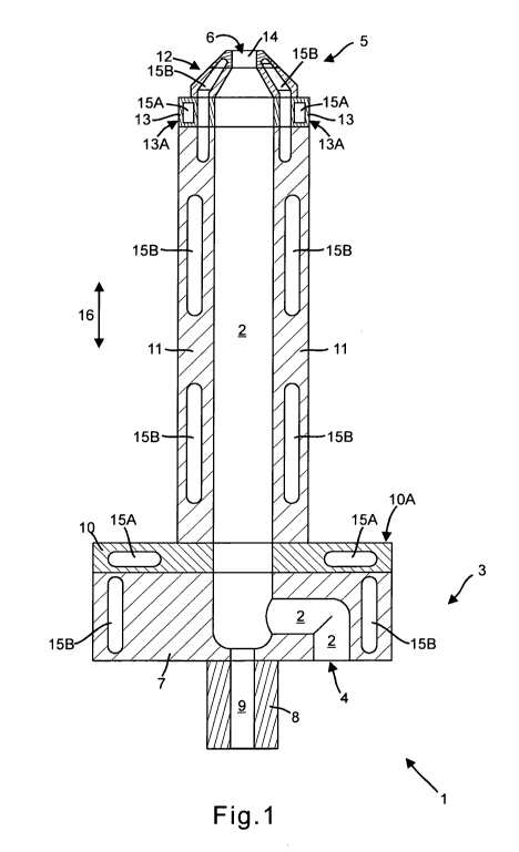
makes contact with
the relatively cool mold at its one end region. This is necessary for sealing
reasons and for
stability.
[0004] The contact surface between the nozzle body and the mold is located on
an
insulating ring that is permanently connected to the nozzle body. Although
this hot runner
nozzle has proven itself in practice, it still has disadvantages. For
instance, despite the
insulating ring, a certain amount of the heat introduced into the nozzle body
by the heating
element is dissipated in the mold of the injection molding tool, which reduces
the
temperature in this part of the nozzle body.
[0005] In the central region of the nozzle located between the end regions,
no heat is
dissipated in the mold. Consequently, heat accumulation is present here
resulting in a higher
temperature.
[0006] For this reason, the object is to create a hot runner nozzle of the
type mentioned
above that permits as uniform a temperature level as possible over its nozzle
length when
heated in the melting position.
[0007] This object is achieved by the invention in that the nozzle body has
at least one
cavity in addition to the passage channel and a guide channel, provided, if
applicable, for a
closing needle.
[0008] In an advantageous manner, during the construction of the hot runner
nozzle by
appropriately forming the at least one cavity, the heat flow in the nozzle
body can be set so
that during use of the hot runner nozzle a largely uniform temperature level
results over the
longitudinal direction of the nozzle body. As the partial region of the nozzle
body surrounding
the cavity can be designed as a single piece, leaks, such as those that may
occur at joints,
can be avoided from the outset in the region of the cavity.
1
CA 02821997 2013-06-17
[0009] The at least one cavity can be produced using a generative
manufacturing process,
in particular using selective laser sintering. In this process, the nozzle
body is created in
layers in that one thin layer of a powder material is applied each time over
the entire area in
a number of operations, for example, using a spreading knife on an appropriate
base. Based
on the geometry data, a laser beam is positioned to sinter the powder at each
processing
location corresponding to those points where the nozzle body is to be created.
The energy
supplied by the laser is absorbed by the powder and results in a localized
sintering or
melting of particles at the processing location. Then, the structure obtained
in this manner is
lowered by the thickness of the layer to apply and to structure another layer
in the same
manner. The process steps described above are repeated until the nozzle body
is finished.
[0010] In one advantageous development of the invention, the cavity is
evacuated or filled
with a medium that has a thermal conductivity different from the material of
the wall of the
nozzle body adjacent to the cavity. If the cavity is evacuated, the cavity
provides a
particularly high thermal insulation. The cavity may also contain a gas, such
as air, however,
to achieve high thermal insulation. However, it is also possible to fill the
cavity with a
preferably liquid or solid medium having high thermal conductivity. In this
way, an effective
thermal transfer to colder locations can be achieved from points where a
particularly large
quantity of heat accumulates during operation of the hot runner nozzle.
[0011] In one advantageous embodiment of the invention, the medium is a
metal having a
higher thermal conductivity than the material of the wall of the nozzle body
adjacent to the
cavity. The metal may contain, in particular, copper and/or aluminum. These
metals have
high thermal conductivity but are available at a relatively affordable cost
and are workable.
The metal or the medium is filled into the cavity when fabricating the hot
runner nozzle
preferably by way of a fill opening provided in the wall of the cavity. If
needed, the cavity may
have a vent opening in addition to the fill opening. The fill opening and, if
applicable, the vent
opening are plugged after filling the cavity. In the case of a solid medium,
the fill and/or vent
opening is preferably plugged by means of the medium itself.
[0012] In a refinement of the invention, the cavity runs in the form of a
ring around the
passage channel. In this way, a very uniform temperature level of the nozzle
body is
provided around the circumference.
[0013] It is advantageous if the nozzle body has at least one contact
surface that can be
connected to a mating surface of an injection molding tool, if the nozzle body
has at least
one first cavity adjacent to the contact surface and at least one second
cavity that is spaced
farther from the at least one contact surface than the first cavity,
[0014] - if the first cavity is filled with a first medium and the second
cavity with a second
medium that has a higher thermal conductivity than the first medium, and/or
2
CA 02821997 2013-06-17
[0015] - if the first cavity is evacuated and the second cavity filled with
a thermally
conductive medium.
[0016] This measure provides a particularly uniform temperature level all
along the nozzle
body.
[0017] In one preferred development of the invention, the nozzle body has a
nozzle tube
surrounding the passage channel wherein the nozzle tube is connected with at
least one
nozzle body part having the contact surface, this part consisting of a
material having a lower
thermal conductivity than the material of the nozzle tube and wherein the at
least one first
cavity is located in the at least one nozzle body part and the at least one
second cavity is
located in the nozzle tube. Different powder materials may also be used to
fabricate the
different partial regions of the nozzle body in a generative process. In this
way, the thermal
flow during operation of the hot runner nozzle from the nozzle body into the
mold of the
injection molding tool is reduced particularly effectively such that an even
more uniform
temperature level results along the longitudinal direction of the nozzle body.
The nozzle tube
preferably consists of metal and the nozzle body part of ceramic.
[0018] Various steels, nonferrous metals, sinter metals, ceramics, etc. are
suitable as
powder materials for the generative fabrication of the nozzle body. These
different materials
can be melted together in a high-strength manner using the laser beam. In
part, even very
wear-resistant materials can be used, for example, to build a guide for the
closing needle in
the nozzle.
[0019] In one advantageous embodiment of the invention, the nozzle body has
a
preferably one-piece nozzle tube surrounding the passage channel wherein the
nozzle tube
has at least two cavities that are spaced apart in the longitudinal direction
of the passage
channel and wherein a section of the nozzle tube that does not have any
cavities is located
in the longitudinal direction between said cavities. This provides both high
mechanical
stability for the nozzle tube and a uniform temperature level on the nozzle
tube.
[0020] If necessary, the nozzle body may have at least two cavities that
are connected to
one another by way of at least one connecting channel that has a smaller cross-
section than
the cavities. In this way, a plurality of cavities can be filled at the same
time with the first
medium and/or the second medium in a simple manner during fabrication of the
nozzle body.
[0021] In one preferred development of the invention, the at least one
cavity or one
section extends in the shape of a spiral or coil around the longitudinal
central axis of the hot
runner nozzle. As a result of this measure, the thermal conductivity can be
influenced if
necessary over the entire length of the nozzle tube.
[0022] It is advantageous if the nozzle body has a base body onto which one
partial
region is applied in layers by means of a generative method, this region
having the at least
one cavity. The base body may, in this respect, consist of a high-strength
material having the
3
CA 02821997 2013-06-17
I
required resistance to pressure, temperature and wear. The base body can be
fabricated
using a conventional manufacturing method. However, it is also conceivable to
manufacture
the base body from a used hot runner nozzle in which, for example, the needle
guide of the
closing needle is worn. In this case, the worn partial region of the needle
guide can be
removed, for example, by grinding off the hot runner nozzle and then, using
the generative
manufacturing method, reapplied on the remaining part of the hot runner
nozzle.
[0023] One exemplary embodiment of the invention is explained below
in more detail
based on the drawing. The single figure shows a longitudinal section through a
hot runner
nozzle.
[0024] Identified with 1, a complete hot runner nozzle for an
injection molding tool has a
nozzle body that has one passage channel 2 for a melt. The passage channel 2
has one
feed opening 4 at a first end region 3 facing the injection molding tool when
in the position of
use and an outlet opening 6 for the melt at a second end region 5 at some
distance from this.
[0025] The hot runner nozzle 1 is broadened at its first end region 3
forming a head
similar to that of a screw. At its end facing away from the outlet opening 6,
the first end
region 3 has a roughly disk-shaped nozzle carrier 7 on whose rear surface
facing away from
the outlet opening 6 are located the feed opening 4 and a first needle guide 8
surrounding a
guide channel 9 for a closing needle, not shown in more detail in the drawing,
that engages
in the passage channel 2. The first needle guide 8 is made of a material that
is more
resistant to wear than the material of a partial region of the nozzle carrier
7 bordering the first
needle guide 8.
[0026] The feed opening 4 is offset perpendicular to the longitudinal
direction of the hot
runner nozzle 1 with respect to the needle guide 8 and the passage channel 2
has a channel
section in the nozzle carrier 7 that runs perpendicular to the longitudinal
direction of the hot
runner nozzle 1, said section connecting with the feed opening 4 with another
channel
section running along the longitudinal axis of the hot runner nozzle 1 to the
outlet opening 6.
[0027] At the end facing away from the outlet opening 6, the first
end region has a nozzle
seat 10 that is also roughly disk shaped and connected over a flat area with
the nozzle
carrier 7, the hot runner nozzle 1 making contact with the injection molding
tool at this seat.
The nozzle seat 10 is bonded with the nozzle carrier and is made of a material
having a
lower thermal conductivity than the material of the nozzle carrier 7. The
nozzle carrier 7 may,
for example, be made of metal and the nozzle seat 10 made of ceramic.
[0028] At its front side facing away from the nozzle carrier 7, the
nozzle seat 10 is bonded
with a nozzle tube 11 that is arranged roughly concentrically with the passage
channel 2 and
runs in the longitudinal direction of the hot runner nozzle 1. The nozzle tube
11 preferably
consists of metal, in particular of steel. To thermally decouple the nozzle
tube 11 from the
4
CA 02821997 2013-06-17
injection molding tool, an air gap is provided between the outer shell of the
nozzle tube 11
and the injection molding tool.
[0029] The nozzle tube 11 has a nozzle section 12 on the end spaced away from
the
nozzle seat 10, this section being connected to the other nozzle tube 11 as a
single piece.
The nozzle section 12 has, at its free end, the outlet opening 6 and the
section tapers
conically toward the outlet opening 6. At the outlet opening 6, the nozzle
section 12 has a
second needle guide 14 located in a straight line extension of the first
needle guide 8 and
made of a material that is resistant to wear.
[0030] Adjacent to the nozzle section 12, the hot runner nozzle 1 has a ring-
shaped
shoulder at its second end region, this shoulder forming a recess holding an
insulating ring
13. The hot runner nozzle 1 makes contact with a support point of the
injection molding tool
on the insulating ring 13.
[0031] In addition to the passage channel 2 and the guide channel 9 for the
closing
needle, the nozzle body has a plurality of first cavities 15A and a plurality
of second cavities
15B. The first cavities 15A are filled with air and the second cavities 15B
with a metal having
a higher thermal conductivity than the material of the nozzle-body walls
bordering the
cavities 15A, 15B involved. The metal may be copper, in particular. The walls
bordering each
of the individual cavities 15A, 15B are connected to one another as a single
piece. In this
way, joints where melts may leak from the nozzle body are avoided on the
cavities 15A, 15B.
[0032] The cavities 15A, 15B are each of a ring shape and surround the passage
channel
2 without interruption. In the nozzle seat 10 and the insulating ring 13, a
first cavity 15A is
provided that serves to reduce the thermal loss from the nozzle body into the
injection
molding tool and/or the interior cavity of the injection molding tool.
[0033] Furthermore, a plurality of second cavities 15B is provided in the
nozzle tube 11.
Second cavities 15B that are adjacent to one another are spaced apart by
nozzle tube
sections, which have no cavities 15A, 15B, in the longitudinal direction of
the nozzle tube 11
marked by the double arrow.
[0034] In the region of the nozzle tube 11, the second cavities 15B are
located roughly in
the center between the inner and outer shells of the nozzle tube 11. With the
exception of
any fill openings provided on the cavities 15B, the second cavities 15B of the
nozzle tube 11
are spaced apart from the outer shell and the inner shell of the nozzle tube
11.
[0035] The thermal conductivity of the nozzle tube 11 is increased by the
second cavities
15B so that, while operating the hot runner nozzle 1, a largely uniform
temperature level is
reached along the nozzle tube 11. Temperature differences that may occur along
the length
of the nozzle tube 11 cause a thermal flow in nozzle tube 11 that reduces the
temperature
difference.
CA 02821997 2013-06-17
[0036] A second cavity 15B that surrounds the passage channel 2 in the shape
of a ring is
provided, also in the nozzle carrier 7. This second cavity 15B is located
between the straight
extension of the outer shell of the nozzle tube 11 and the outer circumference
of the nozzle
carrier 7 and runs concentrically with the second cavities 15B of the nozzle
tube 11. With the
exception of any fill opening provided on the second cavity 15B of the nozzle
carrier 7, the
second cavity 15B is spaced apart from the outer circumference of the nozzle
carrier 7.
[0037] All second cavities 15B may be connected to one another to influence
thermal
conductivity over the entire nozzle length.
[0038] It would
also be feasible to implement the second cavities 15B in the region of the
nozzle tube 11 and the nozzle section 12 as a single piece, for example, as a
spiral-shaped
or coil-shaped cavity winding around the central axis of the hot runner nozzle
1.
6