Note: Descriptions are shown in the official language in which they were submitted.
CA 02822205 2013-06-18
WO 2012/093280 PCT/1B2011/003182
SYSTEMS AND METHODS FOR RECYCLING STEELMAKING CONVERTER EXHAUST
RESIDUE AND PRODUCTS MADE THEREBY
FIELD OF THE INVENTION
[0001] The present invention generally relates to the field of steelmaking.
In particular, the
present invention is directed to systems and methods for recycling steelmaking
converter exhaust
residue and products made thereby.
BACKGROUND
[0002] During the process of making steel, many residues are produced.
Among these residues
is residue from basic oxygen converters. In converter-based steelmaking, high-
velocity oxygen is
injected into a basic oxygen converter, which is typically charged with molten
pig iron, scrap metals,
lime, and iron ore, in order to remove carbon and silicon from the charge and
to form molten steel.
This process produces a large volume of hot fumes that contain fine particles
of the charge materials
and carbon monoxide gas. To avoid polluting the environment, the hot fumes are
scrubbed before
being discharged into the environment. Typically, the fumes are either
quenched with water and
cleaned of suspended metal particles and other solids or passed through an
electrostatic precipitator
to remove such particulate. The remaining gas (carbon monoxide) is drawn off
and is often used as
fuel in the steelmaking process. The solids and the quenching water from the
quenching process
form a sludge that is collected, typically in a settling tank. This residue
sludge, which comprises
metallic iron particles and other solids, is generally separated into "thick"
and "thin" sludges.
[0003] The thick sludge contains the larger solids from the fumes and is
usually either discarded
into landfills or dried and used as sinter feed for blast furnaces that
produces pig iron. The thin
sludge contains the smaller solids from the fumes and is usually discarded
into landfills or used
directly "in natura" as sinter feed for blast furnaces or even directly "in
natura" into pellet feed as a
replacement for bentonite as a binder for producing the pellets. Both
materials are sent to blast
furnaces to become pig iron. Particulates, or dust, removed from the fumes by
an electrostatic
precipitator is similarly collected and is typically discarded into landfills
without being separated
into "thin" and "thick" constituents based on sizing of the particles it
contains.
1
CA 02822205 2013-06-18
WO 2012/093280 PCT/1B2011/003182
BRIEF DESCRIPTION OF THE DRAWINGS
[00041 For the purpose of illustrating the invention, the drawings show
aspects of one or more
embodiments of the invention. However, it should be understood that the
present invention is not
limited to the precise arrangements and instrumentalities shown in the
drawings, wherein:
FIG. 1 is a flow diagram illustrating a method of recycling sludge produced by
a fume scrubbing
system of a basic oxygen converter;
FIG. 2A is a schematic diagram of a continuous sludge processing system
designed and configured
to perform the method of FIG. 1;
FIG. 2B is a schematic diagram of a continuous sludge processing system
designed a configured to
process steelmaking converter fume residue having very fine particulates;
FIG. 3 is a flow diagram illustrating a specific example of a continuous-
processing method of
recycling basic oxygen converter sludge;
FIG. 4 is a photograph of dried thick converter sludge;
FIG. 5 is a photograph of dried particulate remnants of the thick converter
sludge after cleaning,
showing the remaining metallic iron particles and nonmetallic-iron particles;
FIG. 6 is a photograph of the metallic iron particles after processing the
remnant solids of the slurry
cleaning step to concentrate the metallic iron particles by separating them
from the nonmetallic-iron
particles;
FIG. 7 is a photograph of the nonmetallic-iron particles after processing the
remnant solids of the
slurry cleaning step to concentrate the metallic iron particles by separating
them from the
nonmetallic-iron particles;
FIG. 8 is a photograph of a set of briquettes consisting essentially of only
metallic iron particles
recovered from basic oxygen converter sludge;
FIG. 9 is a side elevational view of the acoustic cavitation device of the
converter sludge processing
system of FIG. 2;
FIG. 10 is an enlarged elevational perspective view of one segment of the
acoustic cavitation duct of
FIG. 9;
FIG. 11 is an enlarged view of one end of the acoustic cavitation duct segment
of FIG. 10;
2
CA 02822205 2013-06-18
WO 2012/093280 PCT/1B2011/003182
FIG. 12 is a flow diagram illustrating a method of making pellet feedstock
from steelmaking
converter fume residue;
FIG. 13 is a schematic diagram of a system for making pellet feedstock;
FIG. 14A is a diagram illustrating a pellet car containing conventional
converter feedstock pellets;
FIG. 14B is a diagram of the pellet car of FIG. 14A completely filled with
green pellets made using
the method of FIG. 12 and the system of FIG. 13;
FIG. 15 is a flow diagram illustrating a method of making sinter feedstock
from steelmaking
converter fume residue; and
FIG. 16 is a schematic diagram of a system for making sinter feedstock.
DETAILED DESCRIPTION
[0005] As described in the Background section above, a byproduct of
steelmaking processes that
utilizes basic oxygen converters, such as Linz-Donawitz (LD) converters, is a
converter sludge that
contains metallic iron particles and other solids, including nonmetallic-iron
particles, such as the
calcium oxide, silicon dioxide, aluminum trioxide, magnesium oxide, ferrous
oxide, alkalis, and
zinc. Conventionally, the larger solids in the converter sludge are isolated
into a "thick converter
sludge," and this thick sludge is either disposed of in landfills or used as
sinter feed for making pig
iron. Landfill disposal is undesirable for environmental reasons and because
the metallic iron in the
thick sludge is essentially wasted. In one example, the average metallic iron
content of thick
converter sludge is around 50%. When used as sinter feed for making pig iron,
the thick converter
sludge is mixed with iron ore fines and go normally through the conventional
iron sintering process.
When used as a briquette for direct blast furnace charge the thick converter
sludge is dried, generally
supplemented with binder and formed into briquettes that are then typically
added to a blast furnace
to make pig iron. While the metallic iron in the thick converter sludge is
being recycled in this
process, an undesirable result is that the large amount of the material in the
sinter feed that are not
metallic iron particles, such as alkalis, zinc, and the binder used to make
the briquettes causes
additional slag to form in the blast furnace.
[0006] Some aspects of the present invention are directed to processing
converter sludge so that
metallic iron particles contained in the sludge are efficiently recyclable
without the drawbacks of
conventional converter-sludge-based sinter feed. In one example, a very large
portion of the metallic
iron particles present in the converter sludge are separated from nonmetallic-
iron components of the
3
CA 02822205 2013-06-18
WO 2012/093280 PCT/1B2011/003182
sludge and then formed into coherent bodies without any binder additives or
other contaminants.
The result is bodies that have high mechanical resistance and high metallic
iron content (e.g., greater
than 80%) that can be used as feed for a basic oxygen converter and/or
electric arc furnaces,
essentially as a replacement for scrap iron. Exemplary embodiments of these
aspects are described
below in the context of several specific examples.
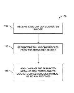
[0007] Referring now to the drawings, FIG. 1 illustrates a method 100 of
agglomerating metallic
iron particles, present in converter sludge, into coherent bodies consisting
essentially of the metallic
iron of the metallic iron particles in the sludge. Those skilled in the art
will readily understand that
this residue sludge is created in the process of scrubbing fumes from the
basic oxygen-converting
process to rid the gas in the fumes of the solids that are also present in the
fumes, such as the
metallic iron particles and nonmetallic-iron solids mentioned above.
[0008] As seen in FIG. 1, method 100 includes only a few high-level steps.
However, those
skilled in the art will readily appreciate that practical applications of
method 100 using current
technologies will typically include multiple sub-steps for effecting the
higher-level steps of
method 100. With that in mind, at step 105, a residue basic oxygen converter
sludge is received
from, for example, a fume scrubber, storage facility, or other place. At step
110, a substantial
portion of the metallic iron particles within the sludge are separated from
all of the non-magnetic-
iron material within the sludge so that essentially all that remains is the
metallic iron particles. Then,
at step 115 the metallic iron particles are agglomerated with one another into
discrete cohesive
bodies, such as briquettes, that can be handled without substantially losing
their integrity. Ideally,
these cohesive bodies are created without binders or any other additives in
order to keep the bodies
as free from nonmetallic-iron material as practicable. As mentioned above,
these cohesive bodies
composed essentially only of pure metallic iron from the metallic iron
particles in the converter
sludge can be used for any suitable purpose, such as for charging a basic
oxygen converter or electric
arc furnace.
[0009] Referring now to FIGS. 2A and 3, these figures illustrate,
respectively, a converter sludge
processing system 200 and a corresponding method 300 of processing converter
sludge using the
system of FIG. 2A to form cohesive bodies composed essentially of the metallic
iron of metallic iron
particles originally in the sludge. For convenience of working with FIGS. 2A
and 3, and
occasionally other figures as well, it is noted that the first one or two
digits of each element/step
numeral used in this disclosure correspond to the number of the figure the
reader should look at to
4
CA 02822205 2013-06-18
WO 2012/093280 PCT/1B2011/003182
see that element/step. For example, for elements having 200-series numerals
the reader should look
at FIG. 2A, and for steps having 300-series numerals, the reader should look
at FIG. 3.
[0010] As seen in FIG. 2A, converter sludge processing system 200 in this
example is located
downstream of a fume scrubbing system 202 that scrubs fumes that emanate from
an LD
converter 204 during oxygen conversion of the charge (not shown) within the
converter using a
high-pressure-oxygen lance 206. As those skilled in the art understand,
scrubbing system 202 cools
the converter fumes and scrubs particulate matter from the fumes, typically by
quenching the fumes
with water (not shown). The products of such scrubbing are the gas 208
(largely carbon monoxide)
originally contained in the fumes and converter sludge 210, which is a mixture
of the particulate
matter from the fumes with the quenching water. In this example, sludge 210 is
captured in a
settling tank 212.
[0011] Referring to FIG. 3, and also to FIG. 2A for references to converter
sludge processing
system 200, at step 305 of method 300 converter sludge 210 is subjected to
classification in which
the sludge is separated into thick converter sludge 214 and thin converter
sludge (not shown). In one
example, thick converter sludge 214 is essentially composed of all of the
solids in the sludge that are
too large to pass through a 325-mesh sieve, i.e., have sizes greater than 44
microns. Of course, other
minimum particle size cutoffs can be used as long as the desired metallic iron
particles are not
excluded from thick converter sludge 214. In the particular embodiment of
system 200 shown, this
classification is performed by an Atkins-type screw conveyor 216. However,
those skilled in the art
will understand that classification can be accomplished in any of a variety of
ways, such as using one
or more cyclones, one or more jig separators, etc. That said, Atkins-type
screw conveyor 216
contributes to the continuous-flow processing nature of exemplary system 200
that is addressed in
more detail below. FIG. 4 shows a sample 400 of thick converter sludge 214
that has been dried for
clarity. FIG. 4 illustrates how the relatively large particles 404 in thick
converter sludge 214, which
include metallic iron particles (typically solid and hollow spheres) and
nonmetallic-iron particles
(such as calcium oxide and silicon dioxide particles), are covered with binder
fines that adhere to
these particles.
[0012] Referring again to FIGS. 2A and 3, at step 310 water 218 is added to
thick converter
sludge 214, here using a conditioner/slurry pump 220, to create a slurry 222
and pump the slurry to
the next stage of system 200. In one example, water 218 is added to thick
converter sludge 214 so
that slurry 222 is about 30% solids. Generally, a suitable slurry will have a
solids percentage in a
CA 02822205 2013-06-18
WO 2012/093280 PCT/1B2011/003182
range of about 20% to about 50%. In this embodiment, conditioner/slurry pump
220 is designed and
configured to produce and pump slurry 222 having 30% solids (70% water) at a
rate of 0.1 m3/min.
[0013] At step 315, the binder fines adhering to the larger particles in
slurry 222 are removed
from the particles. This step can be referred to as a "particle cleaning step"
and can be achieved, for
example, using acoustic cavitation. In the embodiment of converter sludge
processing system 200
shown, particle cleaning step 315 is effected by a vertically oriented
acoustic cavitation device 224
in which the particles are cleaned as slurry 222 flows upward through the
device in a continuous
stream. Further details of exemplary acoustic cavitation device 224 are
described below in
connection with FIGS. 9-11. In other embodiments, other cleaning devices can
be used. FIG. 5
shows a dried sample 500 of the relatively large particles 504 from slurry 222
after particle cleaning
step 315. FIG. 5 clearly shows how particle cleaning step 315 removes the
binder fines that
originally covered the particles in thick converter sludge 214. As also seen
in FIG. 5, particles 504
include metallic iron particles 504A and nonmetallic-iron particles 504B.
[0014] Again referring back to FIGS. 2A and 3, at step 320 the now-cleaned
particles in
slurry 222 are separated into two groups, the metallic iron particles (e.g.,
particles 504A in FIG. 5)
and all other particles, i.e., nonmetallic-iron particles (e.g., particles
504B in FIG. 5), in order to
concentrate the metallic iron particles. In the embodiment of converter sludge
processing
system 200 shown in FIG. 2A, this separation is achieved using a two-stage
separator 226 having
first and second spiral stages 226A, 226B in series with one another. The
metallic iron particles are
typically heavier than the nonmetallic-iron particles, and separator 226
separates the differing
particles based on their weight in a gravity separation process. In this
example, first stage
spiral 226A is a high-grade (HG) series spiral available from Downer EDi
Mining, Carrara,
Australia. First stage spiral 226A separates slurry 222 into a primary
concentrate 228 and a primary
waste 230. It is noted that the 30%-solids composition of slurry 222 was
selected in this example
because of the particular HG spiral 226A used. Here, an HG11 spiral was used,
and this spiral is
most effective with solids percentages in a range of about 27% to about 33%.
With other spiral and
other types of separators the solids content of slurry 222 can be outside this
range as needed.
[0015] Primary concentrate 228 contains the heavier particles from slurry
222, which are largely
the desired metallic iron particles. Primary concentrate 228 is sent off for
further processing, as
described below. Primary waste 230 contains lighter particles, some of which
are metallic iron
particles. Primary waste 230 is sent to second spiral stage 226B in order to
retrieve at least some of
6
CA 02822205 2013-06-18
WO 2012/093280 PCT/1B2011/003182
these smaller metallic iron particles. In this embodiment, second spiral stage
226B is a medium-
grade (MG) series spiral available from Downer EDi Mining and separates
primary waste 230 into a
secondary concentrate 232 and a secondary waste 234. The particles in
secondary concentrate 232
are largely only metallic iron particles, whereas the particles in secondary
waste are largely only
nonmetallic-iron particles. As with primary concentrate 228, secondary
concentrate 232 is sent off
for further processing, as described below. Secondary waste 234 is sent to a
settling tank 236. After
settling, these particles 238, which include calcium carbonate and silicon
dioxide particles, are
collected and dried and can be used, for example, in cement..
[0016] At the end of processing by separator 226, the combination of
primary and secondary
concentrates 228, 232 contains the metallic iron particles in relatively high
concentration, typically
at least 80%. FIG. 6 shows a dried sample 600 of particles 604 contained in
the combination of
primary and secondary concentrates 228, 232. As seen in FIG. 6, virtually all
of particles 604 are
metallic iron particles. In contrast, FIG. 7 shows a dried sample 700 of
particles 238 that were in
secondary waste 234 discarded to settling tank 236 after processing by
separator 226. FIG. 7 clearly
shows that substantially all of particles 238 are nonmetallic-iron particles.
Although a Humphrey's-
type spiral separator 226 is used here, those skilled in the art will readily
understand that the
separation at step 320 can be achieved in any of a variety of other ways, such
as by using a cyclone
separator, a concentration table, a jig separator, and an electromagnet
separator etc.
[0017] Referring back to FIGS. 2A and 3, at step 325 primary and secondary
concentrates 228,
232, which contain a high concentration of metallic particles, are dewatered.
In the embodiment
shown, dewatering is achieved using a dewatering screw conveyor 240, although
in other
embodiments dewatering can be performed in other manners, such as using a
dewatering cyclone,
etc. The outputs of dewatering screw conveyor 240 are the particles 242 from
primary and
secondary concentrates 228, 232, which, again, are largely only metallic iron
particles, and the
mixture 244 of water and very fine particles from the two concentrates. In the
embodiment shown,
mixture 244 is sent to settling tank 236, and the water is reused in other
parts of system 200, such as
in condition/slurry pump 220, wherein it is used to create 30%-solids slurry
222 as described above.
The flow of particles 242 output from dewatering screw conveyor 240 has a
moisture content of
about 20%. At step 330, particles 242 are dried in a suitable dryer 246. In
one example, dryer 246
heats particles to about 200 C to drive the water out/off of the particles.
7
CA 02822205 2013-06-18
WO 2012/093280 PCT/1B2011/003182
[0018] All of the pieces of equipment that contribute to the
separation/isolation of the metallic
iron particles originally in converter sludge 210 can be considered,
collectively, as "separating
equipment" since they participate in the separation/isolation process. In
exemplary converter sludge
processing system 200, such separating equipment includes not only acoustic
cavitation device 224,
which removes fines from the particles in slurry 222, and separator 226, which
concentrates the
metallic iron particles in slurry 222, but also classifying screw conveyor
216, conditioner/pump 220,
dewatering screw conveyor 240, and dryer 246, all of which contribute to the
overall
separating/isolating process.
[0019] At step 335, the now-dried particles 242 are formed into cohesive
bodies, here cohesive
briquettes 248, that can be handled and stored without losing their
cohesiveness. In the embodiment
of converter sludge processing system 200 illustrated, step 335 has two
primary sub-steps 335A,
335B due to the type of equipment used. At sub-step 335A, particles 242 are
formed into loosely
bound briquettes 250 using a high-pressure former 252. In this embodiment,
former 252 is a
briquette press. As one example, former 252 can be 220-metric-ton briquette
press model B220B
available from K.R. Komarek, Wood Dale, Illinois. Because particles are
largely only metallic iron
particles (typically microspheres) and no binder is used, loosely bound
briquettes 250 have very low
mechanical resistance and, therefore, generally cannot be handled without
losing their initial
integrity.
[0020] Consequently, at sub-step 335B, loosely bound briquettes 250 are
heat-treated in a
heat treatment device 254 so as to transform the loosely bound briquettes into
cohesive
briquettes 248 that remain largely intact during normal handling and storage,
if any. In one example,
at sub-step 335B loosely bound briquettes 250 are heated to a temperature
sufficiently high, typically
greater than about 700 C, for a time long enough to transform them into
cohesive briquettes 248
having mechanical resistance and hardness that makes it possible to handle and
store them without
causing them to substantially lose their original shape. In one embodiment,
heat treatment
device 254 is a continuous-feed furnace that complements the rest of converter
sludge processing
system 200, in which the primary components are continuous-feed components. In
one example,
heat treatment device 254 is an 8-meter-long furnace that provides a 25-minute
residence time and
heats loosely bound briquettes 250 at a temperature of about 850 C to about
900 C. Under these
conditions, thermal migration amongst the atoms of the interfaces of particles
242 within loosely
bound briquettes 250 is promoted to a point that the particles become
cohesively bound together and
8
CA 02822205 2013-06-18
WO 2012/093280 PCT/1B2011/003182
form cohesive briquettes 248. Energy usage can be minimized by heating loosely
bound
briquettes 250 only enough to enable this cohesive bonding. Of course, the
particles can be heated
until fusion occurs, but this requires more energy. All of the pieces of
equipment that contribute to
the forming of cohesive briquettes 248 can be considered, collectively, as
"forming equipment." In
exemplary converter sludge processing system 200, such forming equipment
includes high-pressure
former 252 and thermal treatment device 254.
[0021] Cohesive briquettes 248 generally do not lose their cohesiveness
until reaching their
fusion point. FIG. 8 shows a set 800 of actual cohesive briquettes 248 made
using converter sludge
processing system 200, which includes the K.R. Komarek B220B briquetting press
mentioned
above, which produces, for example, briquettes that are 3m x 2.5cm x 1.5cm in
size. Once
cohesive briquettes 248 have been created, they can be used as desired. For
example, as mentioned
above cohesive briquettes can be used as charge material for a basic oxygen
converter or an electric
arc furnace.
[0022] As mentioned above, exemplary converter sludge processing system 200
is designed and
configured so that the steps of method 300 are performed with a continuous
flow through the system.
That is, all primary pieces of equipment selected for this system do not
process batches; rather, they
process in continuous flows. For example, the example used for heat-treatment
device 254 is a
furnace in which loosely bound briquettes 250 are heated as they progress
along the length of the
furnace. As other examples, Atkins-type screw conveyor 216, Humphrey's-type
spiral
separator 226, and dewatering screw conveyor 240 all operate in continuous
processing modes. That
said, those skilled in the art will appreciate that in alternative
embodiments, any one of the disclosed
pieces of continuous processing mode equipment can be replaced by
corresponding batch processing
equipment.
[0023] In addition, those skilled in the art will readily appreciate that
depending on the nature of
the equipment used, two or more pieces of equipment in converter sludge
processing system 200 of
FIG. 2A can be replaced by a single piece of equipment that achieves the same
end result as the
pieces of equipment being replaced. For example, in system 200, step 335 of
forming cohesive
bodies of the metallic iron particles is performed using high-pressure former
252 and heat treatment
device 254. However, a single piece of equipment designed and configured to
heat the particles
during pressure forming can replace two separate devices 252, 254. Those
skilled in the art will
understand where such replacements can be made.
9
CA 02822205 2013-06-18
WO 2012/093280 PCT/1B2011/003182
[0024] An important component of exemplary converter sludge processing
system 200 is
acoustic cavitation device 224 because of the role it plays in the removals of
the binder fines from
the larger particles slurry 222 that allow for the production of such high
purity metallic iron
briquettes 248. Like other components of system 200 mentioned above, acoustic
cavitation
device 224 is designed and configured to process a continuous flow of slurry
222 as it flows through
the device. In order to achieve this, acoustic cavitation device 224 has a
unique design that is more
particularly shown in FIGS. 9-11.
[0025] Referring now to FIG. 9, the exemplary acoustic cavitation device
224 shown is designed
and configured to process an about 15%-solids slurry to an about 50%-solids
slurry composed of
thick converter sludge and water at the rate of 10 m3/hour. In the particular
example of FIG. 2A, the
percentage of solids in slurry 222 is about 30%. This should be kept in mind
when reading the
following description of device 224 to understand that other embodiments can
have different
configurations, dimensions, etc., especially when designed for other
processing rates.
[0026] Acoustic cavitation device 224 includes an acoustic cavitation duct
900, an inlet 904, and
an outlet 908, and, when installed, the duct is oriented vertically with the
inlet at the lower end and
the outlet at the upper end. It is noted that it is preferred, but not
absolutely necessary, that duct 900
be oriented vertically or inclined, rather than horizontally, since a
horizontal orientation could cause
precipitation of solids within the duct. Having inlet 904 at the lower end
also helps in controlling the
time that slurry 222 (FIG. 2A) is exposed to the acoustic cavitation cleaning
action. In this example,
acoustic cavitation duct 900 is 5 meters long in the direction of flow between
inlet 904 and outlet
908, and is made up of five identical 1-meter-long segments 900A-E secured to
each other via
flanged and bolted connections 912A-D. Inlet 904 and outlet 908 are similarly
secured to acoustic
cavitation duct 900 via flanged and bolted connections 916A-B. As seen best in
FIGS. 10 and 11,
acoustic cavitation duct 900 defines an internal passageway 1000 having a
rectangular transverse
cross-sectional shape of approximately 70 mm x 32 mm in size.
[0027] As seen in FIG. 10, each acoustic cavitation duct segment 900A-E
includes eleven
ultrasonic transducers spaced evenly along that segment, with six transducers
1004A-F on one side
of that segment and five transducers 1008A-E on the other side. Transducers
1004A-F, 1008A-E
provide acoustic emissions of compression and decompression waves that promote
cavitation within
slurry 222 (FIG. 2A) as it flows continuously through duct 900. This action
not only cleans binder
CA 02822205 2013-06-18
WO 2012/093280 PCT/1B2011/003182
fines and other surficial matter from the particles in slurry 222, but it also
renders unnecessary
conventional static residence times and conventional agitators.
[0028] In this example, ultrasonic transducers 1004A-F, 1008A-E are each
piezoelectric
transducers, with transducers 1004A-F being 50 W, 25 kHz transducers and
transducers 1008A-E
being 50 W, 40 kHz transducers. Thus, entire acoustic cavitation duct 900 made
up of the five like
segments 900A-E has a total of 55 ultrasonic transducers 1004A-F, 1008A-E,
with 30 of the
transducers being 50 W, 25 kHz transducers and 25 of the transducers being 50
W, 40 kHz
transducers. Transducers 1004A-F, 1008A-E are powered in groups of five by
eleven 250 W power
supplies 920A-K.
[0029] Referring to FIGS. 2A and 9, acoustic cavitation device 224
generally works as follows.
When slurry 222 enters inlet 904, fines are bound to the metallic and
nonmetallic materials that
largely form thick converter sludge 214. As slurry 222 is exposed to acoustic
cavitation duct 900,
the metallic iron particles (see particles 504A of FIG. 5), which are
typically spherical in shape, start
to vibrate at a frequency that is determined by the ultrasound generated by
transducers 1004A-F,
1008A-E (FIG. 10). The frequency at which the metallic iron particles vibrate
is different from
(higher than) the frequency at which the nonmetallic material vibrates, and
this promotes the
removal of the fines from the metallic iron particles. In the present example,
two different
ultrasound frequencies are used to produce a uniform sound field of intense
ultrasonic cavitation
within slurry 222, which maximizes the reaction kinetics within the linear
space allotted within
acoustic cavitation duct 900. The sound energy produces drastic process rate
changes and quality
enhancements down to the molecular level.
[0030] Those skilled in the art will readily appreciate that acoustic
cavitation device 224 shown
is merely one example, and that many other configurations are possible. Design
considerations for
designing a continuous-flow acoustic cavitation device include the composition
of the slurry at issue,
the flow rate of the slurry, the applied power of the ultrasound, the
residence time of the slurry in the
acoustic cavitation duct, and the processing rate required, among others. It
appears that the power
should be greater than 7W/s and that the residence time should be at least
about 2.5 seconds for most
commercial applications. Alternative configurations of the acoustic cavitation
device can have
passageways that differ in size, transverse cross-sectional shape, length,
straightness, etc.
Alternative configurations can also have different numbers of transducers and
different transducer
locations and arrangement. Those skilled in the art will be able to design,
make, and use acoustic
11
CA 02822205 2013-06-18
WO 2012/093280 PCT/1B2011/003182
cavitation devices that provide the desired/necessary cleaning function
without undue
experimentation.
[0031] Whereas FIGS. 2A and 3 are directed to inputting thick sludge 214
(FIG. 2A) into
conditioner/slurry pump 220 (see also step 310 of method 300 of FIG. 3), FIG.
2B illustrates a
system 258 that is particular adapted for processing an input residue 262
containing relatively fine
iron-oxide containing particles as compared to thick sludge 214 of FIG. 2A.
Examples of input
residue 262 of FIG. 2B include thin sludge, such as could be taken from the
screw conveyor 216 of
FIG. 2A as the part of sludge 210 that does not make it to the top of the
conveyor as thick sludge,
and dust from an electrostatic precipitator (not shown) that would take the
place of scrubbing
system 202 in FIG. 2A.
[0032] As seen in FIG. 2B, residue 262, be it thin sludge, electrostatic
precipitator dust, etc., is
mixed with water, here in a conditioner/slurry pump 268 to create a slurry 272
and pump the slurry
to the next stage of system 258. In one example, water 218 is added to residue
262 so that slurry 272
is about 30% solids. Generally, a suitable slurry will have a solids
percentage in a range of about
20% to about 50%. In this embodiment, conditioner/slurry pump 268 is designed
and configured to
produce and pump slurry 272 having 30% solids (70% water) at a rate of 0.1
m3/min.
[0033] Conditioner/slurry pump 268 pumps slurry 272 to a disaggregating
apparatus 276 that
largely disaggregates iron-oxide-containing particles from particles that do
not contain iron oxide.
In this example, apparatus 276 is a vertically oriented acoustic cavitation
device in which the
particles are disaggregated as slurry 272 flows upward through the device in a
continuous stream.
Further details of an exemplary acoustic cavitation device 224 that can be
used as disaggregating
apparatus 276 are described above in connection with FIGS. 9-11. In other
embodiments, another
disaggregating apparatus can be used for apparatus 276.
[0034] Still referring to FIG. 2B, the now-disaggregated particles in
slurry 272 are separated into
two groups, metallic particles 280 and nonmetallic particulates 284, which
contain a relatively large
amount of iron oxide. In the embodiment of system 258 shown in FIG. 2B, this
separation is
achieved using a magnetic separator 288 having a magnet 288A that attracts
metallic particles 280,
though the separating can be accomplished using other devices known in the
art. If desired, the now
separated metallic particles 280 can be processed in the manner of particles
242 of FIG. 2A into
cohesive briquettes similar to briquettes 248 of FIG. 2A using techniques
described above. The now
12
CA 02822205 2013-06-18
WO 2012/093280 PCT/1B2011/003182
separated nonmetallic particulates 284 of FIG. 2B can be used in making either
pellet or sinter
feedstock, or both, for example in the manners described below in connection
with FIGS. 12 to 16.
[0035] FIG. 12 illustrates a method 1200 of making pellet feedstock in
accordance with various
aspects of the present invention. At step 1205, particulates are extracted
from exhaust fumes of a
steelmaking converter process to form a residue. As mentioned above, the
residue can be, for
example, sludge resulting from a fume-quenching process or dust from an
electrostatic precipitation
process, among others. At step 1210, the residue is processed to separate
metallic particles and
nonmetallic particulates from one another. In one example, this is done using
the acoustic-duct
disaggregation techniques depicted and described relative to FIG. 2B, above.
[0036] Referring now not only to FIG. 12 but also to FIG. 13 for
visualizations of the rest of
method 1200, if the now-separated, substantially nonmetallic particulates,
represented at element
numeral 1300 in FIG. 13 (these particulates can be particulates 284 of FIG.
2B), are wet following
separation at step 1210, at optional step 1215 the nonmetallic particulates
can be dried, for example,
until they reach about 4% to about 1% moisture content. In one example,
optional step 1215 can be
performed by non-heating-type drier 1304, such as a press-filter or an Outotec
vacuum-belt filter
(formerly Larox), available from Outotec Oyj, Espoo, Finland. Non-heat drying
tends to maintain
the hygroscopicity of particulates 1300, which is a desirable characteristic
for using the particulates
as a binder in a pelletization system, such as system 1308 of FIG. 13, for
creating pellet
feedstock 1312 for making pig iron.
[0037] At step 1220, nonmetallic particulates 1300, now represented by feed
bin 1316, is mixed
with one or more other materials that will be used to create pellet feedstock
1312. In this example,
those other materials include iron ore (represented by feed bin 1320),
limestone (represented by feed
bin 1324), bentonite (represented by feed bin 1328), and, if needed, coal
(represented by feed
bin 1332). All of the materials in feed bins 1316, 1320, 1324, 1328, and 1332
are combined with
one another according to a specific mix determined by the inputs used to
produce pellet
feedstock 1312. Except for particulates 1300 extracted from the exhaust fume
residue, those skilled
in the art will know how to determine mix ratios depending on the types and
character of the mix
materials, as well as the chemistry of the converter charge and other
materials added to the blast
furnace used to make the pig iron. For example, bentonite, represented by feed
bin 1328, is often
added in a range of about 4 kg to about 25 kg per metric ton of produced
pellet feedstock 1312.
Particulates 1300 are added in a suitable amount, such as about 4 kg/metric
ton of pellet feedstock to
13
CA 02822205 2013-06-18
WO 2012/093280 PCT/1B2011/003182
about 18 kg/metric ton of pellet feedstock. The materials from feed bins 1316,
1320, 1324, 1328,
and 1332 can be mixed in any suitable manner, such as by using a rotary mixer
1336 or other mixing
device, so as to produce a mix 1340 that is the precursor to pellet feedstock
1312. In FIG. 13,
mix 1340 is shown as being temporarily stored in a storage bin 1344, but this
need not be so in other
pellet forming systems that fall within the scope of the present disclosure.
100381 At step 1225, mix 1340 is processed into suitably sized green
pellets 1348 (i.e., pellets
that have not yet been heat treated). In pellet forming system 1308 of FIG.
13, this processing is
achieved by a rotating-drum-type pelletizer 1352 and a belt-type sieve 1356
that selects the properly
sized pellets output by the pelletizer. Of course, other types of equipment
can be used to create
properly sized green pellets 1348. Further description of the equipment used
to form suitably sized
green pellets 1348 is not necessary, since such equipment is known in the art
for producing
conventional pellet feedstock for making pig iron.
[0039] At step 1230, green pellets 1348 are cooked and cooled to create
finished pellet feedstock
1312. In the example shown in FIG. 13, green pellets 1348 are cooked by a
conventional pellet-
feedstock furnace system 1360 that uses pellet cars 1364, here three pellet
cars 1364A, 1364B, and
1364C are shown, to carry the initially green pellets 1348 into the furnace.
Each pellet car 1364 is
made of a high-temperature-resistance material that allows initially green
pellets 1348 to reach about
1,250 C to allow them to be cooked. The cooking process causes the initially
green pellets 1348 to
become coherent pellet feedstock 1312 that is relatively very resistant to
mechanical damage.
Following cooking, pellet feedstock 1312 are cooled, sieved as necessary to
select the proper size of
pellets, and stored, in any order. The addition of largely nonmetallic
particulates 1300 (FIG. 13)
recovered from converter exhaust fume residue into pellet feedstock 1312 is
similar to the addition
of bentonite in conventional pelletization in that both materials are
hygroscopic. However, an
important difference is that nonmetallic particulates 1300 contain iron oxide,
which raises the total
iron content of pellet feedstock 1312 relative to conventional pellet
feedstock. In one example, the
total iron content of pellet feedstock 1312 is about 0.8% by weight, whereas
the total iron content of
conventional pellet feedstock is about 0.3% by weight. In addition, pellet
feedstock 1312 has
relatively low amounts of silicon and alumina compared to conventional pellet
feedstock because of
the reduction in bentonite. Essentially, the amounts of silicon and alumina in
pellet feedstock 1312
is due to residuals in nonmetallic particulates 1300.
14
CA 02822205 2013-06-18
WO 2012/093280 PCT/1B2011/003182
[0040] When a pellet-car-based cooking technique is used for cooking green
pellets 1348,
unique properties of the green pellets resulting from the incorporation of
nonmetallic
particulates 1300 allow for much higher cooking efficiencies and cooking
throughput when
compared to conventional green pellets that do not contain nonmetallic
particulates from converter
exhaust fume residue. To illustrate, FIG. 14A illustrates a pellet car 1400,
which corresponds to any
one of pellet cars 1364 of FIG. 13, that is filled in a conventional manner
with conventional pellet
feedstock 1404. The conventional manner of filling pellet car 1400 is to
essentially line the
interior 1408 of the pellet car with already cooked conventional pellets 1404A
and then fill the
remainder of the interior with conventional green pellets 1404B. This is done
because conventional
green pellets 1404B do not have the mechanical strength (compressive
resistance) that would be
required to fill entire interior 1408 of pellet car 1400. Although pellet car
1400 could be completely
filled with green pellets 1404B if they had sufficient mechanical strength,
their limited strength does
not allow this. Consequently, the amount of green pellets 1404B that are
cooked in each load is
significantly reduced by the volume of already cooked pellets 1404 needed to
prevent crushing and
crumbling of the green pellets. Conventional cooking processes typically
require 70% to 85% green
pellets and 30% to 15% cooked pellets. In a process of the present invention,
the amount of cooked
pellets can be reduced to 0%.
[0041] In contrast, green pellets made in accordance with aspects of the
present invention that
include largely nonmetallic particulates recovered from converter exhaust
fumes, such as green
pellets 1348 of FIG. 13, have much higher mechanical strength than
conventional green pellets not
containing such particulate. For example, the present inventors have observed
that green pellets
made in accordance with the present invention have mechanical strength up to
40% greater than the
strength of conventional green pellets. Indeed, this higher mechanical
strength allows entire
interior 1408 of pellet car 1400 to be filled entirely with green pellets 1412
containing the exhaust
fume residue particulates of the present disclosure, as illustrated in FIG.
14B. Because the entire
volume of pellet car 1400 is utilized for green pellets 1412, the throughput
and efficiency of cooking
these green pellets is much higher than cooking conventional green pellets
1404B, which, again,
only occupy a portion of the volume of interior 1408 of pellet car 1400, as
illustrated in FIG. 14A.
[0042] FIG. 15 illustrates a method 1500 of making sinter feedstock in
accordance with various
aspects of the present invention. At step 1505, particulates are extracted
from exhaust fumes of a
steelmaking converter process to form a residue. As mentioned above, the
residue can be, for
CA 02822205 2013-06-18
WO 2012/093280 PCT/1B2011/003182
example, sludge resulting from a flume-quenching process or dust from an
electrostatic precipitation
process, among others. At step 1510, the residue is processed to separate
metallic particulates and
nonmetallic particulates from one another. In one example, this is done using
the acoustic-duct
disaggregation techniques depicted and described relative to FIG. 2B, above.
[0043] Referring now not only to FIG. 15 but also to FIG. 16 for
visualizations of the rest of
method 1500, if the now-separated, substantially nonmetallic particulates,
represented at element
numeral 1600 in FIG. 16 (these particulates can be particulates 284 of FIG.
2B), are wet following
separation at step 1510, at optional step 1515 the nonmetallic particulates
can be dried, for example,
until they reach about 4% to about 1% moisture content. In one example,
optional step 1515 can be
performed by non-heating-type drier 1602, such as a press-filter or an Outotec
vacuum-belt filter
(formerly Larox), available from Outotec Oyj, Espoo, Finland. Non-heat drying
tends to maintain
the hygroscopicity of particulates 1600, which is a desirable characteristic
for using the particulates
as a binder in a sinter-feedstock-making system, such as system 1604 of FIG.
16, for producing
sinter feedstock 1606 for making pig iron.
[0044] Nonmetallic particulates 1600 have all of the chemical properties of
a sinter feed, but
since it results from a process that separates the iron oxide, limestone, and
other components by size,
it is typically a very fine material, as depicted at element numeral 1600A in
FIG. 16. Typically the
size of the material is lower than 325 mesh. When nonmetallic particulates
1600 are considered too
fine for effective processing into sinter feedstock 1606, at step 1520 the
particulates are processed
into suitably sized micro-pellets 1608, for example using micro-pelletizing
equipment 1610. In one
example, "suitably sized" means a size that is larger than a 60 mesh, i.e.,
larger than about 0.25 mm.
[0045] In one embodiment of micro-pelletizing equipment 1610, nonmetallic
particulates 1600
are put into a feed bin 1612. Then, nonmetallic particulates 1600 are mixed
with a binder
(represented by feed bin 1614) and water (represented by tank 1616) in
suitable amounts using a
mixer 1618. As those skilled in the art will readily appreciate, the amounts
of binder 1614 and
water 1616 mixed with nonmetallic particulates 1600 will vary depending on the
type of binder used,
as well as the particular character and chemistry of the particulates. Binder
1614 can be any suitable
organic or inorganic binder or a combination thereof In a specific example,
binder 1614 is a pre-
gelatinized corn flour. When such corn flour is used as binder 1614, it can be
mixed with
nonmetallic particulates 1600 in a proportion in a range of about 2% to about
12% of the total
16
CA 02822205 2013-06-18
WO 2012/093280 PCT/1B2011/003182
mixture by weight. In this example, water 1616 can be added to the mixture of
particulates 1600 and
corn flour in a proportion of about 28% to about 42% of the total mixture 1620
by weight.
[0046] Mixture 1620 is then sent to an extruder 1622 that produces green
micro-pellets 1624,
which are then heated at a temperature in a range of about 80 C to about 250 C
to cook them and
give them a relatively high mechanical strength. This heating can be
performed, for example, using
a hot plate (not shown), hot belt 1626, or low-rotation furnace (not shown),
among other things. The
cooked micro-pellets 1624A are then sieved, for example using a belt sieve
1628, to separate out
particles that do not meet the established size criteria. In the foregoing
example, particulates in
cooked micro-pellets 1624A smaller than 60-mesh are removed. In this
embodiment, these
unacceptably small particles are recycled and again combined into mixture
1620, as illustrated by
recycling line 1630. In other embodiments, the unacceptably small particles
can be discarded or
used elsewhere. The acceptably sized cooked micro-pellets 1624A are micro-
pellets 1608. The
relatively much larger size of micro-pellets 1608 can be seen by comparing the
relative sizes of the
micro-pellets represented at numeral 1608A with the starting nonmetallic
particulates 1600
represented at numeral 1600A. This relatively larger size of micro-particles
1608 means that
particulates 1600 can be used without impacting the air permeability of the
sintering process
(described below) as would happen if the very small sized particulates 1600
were used without
micro-pelletization. Consequently, the productivity of the sintering plant
will not decrease relative
to producing sinter feed using conventional materials.
[00471 At step 1525, micro-pellets 1608, now represented as feed bin 1632,
is mixed with one or
more other materials to produce a mix 1634 that will be used to create sinter
feedstock 1606. In this
example, those other materials include iron ore (represented by feed bin
1636), limestone
(represented by feed bin 1638), and coal (represented by feed bin 1640). All
of the materials in feed
bins 1632, 1636, 1638, and 1640 are combined with one another according to a
specific mix
determined by the inputs used to produce sinter feedstock 1606. Except for
micro-pellets 1608 made
from particulates 1600 extracted from the exhaust fume residue, those skilled
in the art will know
how to determine mix ratios depending on the types and character of the mix
materials, as well as
the chemistry of the converter charge and other materials added to the blast
furnace used to make the
pig iron. Mixing of materials 1632, 1636, 1638, and 1640 is performed using a
mixer, here a rotary
mixer 1642, after the materials have been pre-watered at a watering station
1644. In this example,
mix 1634 is watered again at watering station 1646 and sent to a storage/feed
bin 1648.
17
CA 02822205 2013-06-18
WO 2012/093280 PCT/1B2011/003182
[0048] At step 1530, mix 1634 is processed into finished sinter feedstock
1606. In the example
shown in FIG. 16, mixed material 1634 is cooked by a conventional sinter-
feedstock furnace
system 1650 that uses sinter cars, here a single sinter car 1652 is shown, to
carry the wet mixed
material 1634 into a furnace 1654. Each sinter car 1652 is made of a high-
temperature-resistance
material that allows initially wet mixed material 1634 to reach from about 800
C to about 1,200 C
to allow the material to be cooked. The cooking process causes the initially
wet mixed
material 1634 to become a largely monolithic body 1656. Following cooking,
monolithic body 1656
is crushed by a suitable crusher 1658 and filtered by a suitable device 1660
to remove any fines 1662
unwanted in the final sinter feedstock 1606. Any removed fines 1662 removed by
filtering and/or
any fines collected in furnace 1654 can be recycled back to micro-pelletizing
equipment 1610.
Optionally, after filtering, sinter feedstock 1606 can be cooled, for example,
by cooling fans 1664
and either stored or sent directly to a pig-iron-making process.
[0049] Exemplary embodiments have been disclosed above and illustrated in
the accompanying
drawings. It will be understood by those skilled in the art that various
changes, omissions and
additions may be made to that which is specifically disclosed herein without
departing from the
spirit and scope of the present invention.
18