Note: Descriptions are shown in the official language in which they were submitted.
CA 02822270 2013-07-31
SPRINKLER ASSEMBLY
BACKGROUND
= [0001] The
statements in this section merely provide background
information related to the present disclosure and may not constitute prior
art.
[0002] The present disclosure relates to a sprinkler assembly and,
more particularly, to a sprinkler assembly that exhibits reduced energy
losses,
which may be used in both residential and commercial applications, including
storage applications, and further may be used in a control mode or a
suppression mode.
[0003] Significant energy losses occur at the sprinkler assemblies
where the fluid is dispersed. Conventional sprinkler assemblies include a base
with a passageway, an inlet opening, and a discharge opening, which is adapted
for connecting to the system piping, and a deflector that is supported spaced
from the base, typically by a pair of arms that extend from the base. The arms
are often joined at their distal ends by a boss, which is used to mount the
deflector to the arms. Pendent sprinklers and upright sprinklers typically
include
deflectors with a solid central portion and a plurality of tines that extend
radially
outwardly from the central portion for dispersing the fluid as it flows across
the
solid central portion, which is mounted to the boss and typically aligned with
the
discharge opening of the base. Sidewall sprinklers typically include a
deflector,
also with a solid central portion with tines extending from the central
portion and
a blade that is positioned above the central portion to direct the fluid that
flows
above the central portion outwardly and downwardly. In each case, when the
fluid flows from the discharge opening of the base the fluid impinges on the
boss
and on the central portion of the deflector. The boss and deflector disperse
the
fluid radially outward, and the fluid is thereafter further dispersed by the
tines,
and in the case of the sidewall sprinklers also by the blade. This results in
a
sizeable energy or head loss in the fluid at the sprinkler assembly.
Significant
savings can be realized for a sprinkler system if the supply pressure to the
sprinkler assembly can be reduced. As would be understood by those skilled in
1
CA 02822270 2013-07-31
the art, where the supply pressure to the sprinkler assemblies of a system can
be reduced, the size of the piping delivering the fluid to the sprinkler
assemblies
can be reduced and/or the size of the system pump can be downsized. If
comparable performance of a sprinkler assembly can be provided at a lower
6 pressure for any given system, the need for a pump might even be avoided.
Any
of these modifications could provide significant savings in the installation
cost of
a fire protection system. Accordingly, a sprinkler assembly that can disperse
fluid
with a reduced head loss may reduce the required pressure at the sprinkler
assembly and, hence, provide cost savings for the installation of a fire
protection
system incorporating such sprinkler assemblies.
SUMMARY
[0004] According to the present invention a sprinkler assembly is
provided that is adapted to reduce the energy and hence head loss of a fluid
as it
flows from the sprinkler assembly.
[0005] In one form of the invention, a sprinkler assembly includes a
body and a support extending from the body. The body includes a passageway,
an inlet opening, and a discharge opening. In addition, the sprinkler assembly
includes a flow-shaper member and a closure device release* positioned at the
discharge opening to close the passageway. A heat responsive trigger is
mounted to releasably retain the closure device at the discharge opening of
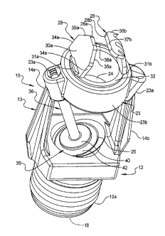
the
body and release the closure device from the discharge opening when the heat
responsive trigger is heated to a temperature associated with a fire. The flow-
shaper member has at least one contact surface for shaping the flow of fluid
25' from the discharge opening when the closure device is released from the
discharge opening. The support and the flow-shaper member are configured so
that they do not block the flow of fluid from the discharge opening along the
axis
of the body to reduce the impediment to the flow of fluid from the discharge
opening when the closure device is released from the discharge opening and
thereby reduce the head loss in the fluid flowing from the sprinkler assembly.
[0006] In one aspect, the support has an opening aligned along the
axis of the body wherein at least some of the fluid flowing from the discharge
2
CA 02822270 2013-07-31
opening flows through the opening. For example, the support's opening may
have a diameter of at least 0.4 inch and, more typically, in a range of about
0.5
to 2.0 inches.
[0007] In another aspect, the flow-shaper member may be located at
[0008] In further aspects, the flow-shaper member projects from the
[0009] In further aspects, the heat responsive trigger includes a heat
sensitive member that extends between the support and the body. For example,
the heat sensitive member may have a longitudinal axis that extends between
[0010] In another aspect, the discharge coefficient or "Ku factor of the
sprinkler assembly, which equals the flow of fluid, such as water, in gallons
per
[0011] In yet another aspect, the Response Time Index (RTI) of the
3
CA 02822270 2013-07-31
[0012] In another form of the invention, a sprinkler assembly includes a
body and a support that extends from the body. The support has a transverse
member with an opening at least generally aligned along the axis of the body =
that is larger in diameter than the discharge opening of the sprinkler body
wherein at least some, and preferably most, of the fluid flowing from the
discharge opening flows through the support.
[0013] In one aspect, the opening is adapted to shape the flow of fluid
flowing from the opening. For example, the sprinkler assembly may include a
flow-shaper with one or more flow-shaper members at or near the opening of the
support.
[0014] According to another form of the invention, a sprinkler assembly
includes a body and a frame that extends from the body. The frame has an
opening at least generally aligned along the axis of the body that is larger
in
diameter than the discharge opening of the sprinkler body wherein at least
some,
and preferably most, of the fluid flowing from the discharge opening flows
through the opening of the frame. In addition, the sprinkler assembly includes
a
flow-shaper member provided at the discharge side of the frame's opening,
which shapes the flow of fluid flowing from the opening of the frame.
[0015] In yet another form of the invention, a sprinkler assembly
includes a body, a support, which extends from the body, and a heat sensitive
trigger. The body includes an inlet opening, a passageway extending from the
inlet opening to a discharge opening, and an axis that extends from the
discharge opening. The trigger includes a heat sensitive member that extends
between a mounting surface of the support and the body, with the mounting
surface being offset from the axis of the body. In this manner, the heat
sensitive
member is offset from the axis to reduce the impediment to the flow of fluid
flowing from the discharge opening when the discharge opening is opened and
thereby reduce the energy loss in the fluid flowing from the discharge
opening.
[0016] In one aspect, the support comprises a frame with a pair of
arms. The frame includes an opening that is aligned along the axis wherein
fluid
flows through the frame. In a further aspect, the frame's opening is sized so
that
most, if not all, the fluid flows from the discharge opening of the body flows
4
CA 02822270 2013-07-31
through the frame. For example, the frame's opening may be sized so that its
diameter is at least as large as the diameter of the discharge opening.
[0017] In another aspect, the axis comprises a central axis that
extends through the centers of each of the inlet and discharge openings.
[0018] In other aspects, the sprinkler assembly includes at least one
fluid flow-shaper member at the frame, which shapes the flow of fluid passing
through the frame. Optionally, the flow-shaper member is provided at the
frame's
opening and, further, optionally mounted in the opening of the frame. For
example, the flow-shaper member may comprise a tab, which is located adjacent
the opening of the frame to thereby shape the flow of fluid flowing from the
opening of the frame. In a further aspect, the sprinkler assembly includes a
pair
of flow-shaper members. For example, the flow-shaper members may be
generally aligned on opposed sides of the frame's opening and offset from the
axis of the body to thereby at least partially envelop the flow of fluid as it
flows
from the frame's opening.
[0019] In further aspects, the sprinkler assembly includes an
annular
member and a pair of tabs that extend from the annular member. The tabs form
a pair of flow-shaper members. For example, the annular member may be
mounted in the frame's opening wherein fluid flowing through the frame's
opening flows through the annular member.
[0020] According to yet another aspect, the body of the sprinkler
includes an insert, which forms the discharge opening. For example, the insert
may include a support surface for supporting the heat sensitive member and,
preferably, a support surface that is angled with respect to the axis of the
body.
In this manner, when the heat sensitive member is compressed between the
body and the mounting surface, the compression forces will be aligned along
the
longitudinal axis of the heat sensitive member. Suitable heat sensitive
members
include a frangible bulb or the like.
[0021] Accordingly, the present disclosure provides a sprinkler
assembly that is adapted to reduce the head loss of the fluid as it flows from
the
sprinkler assembly, thus, potentially reducing the required supply pressure to
the
sprinkler assembly or increasing the pressure of the fluid as it is dispersed
from
5
CA 02822270 2013-07-31
the fire suppressant system or a combination of both. As would be understood
by those skilled in the art, where the supply pressure to the discharge
devices of
the system can be reduced, the size of the piping delivering the fire
suppressant
fluid to the discharge devices can be reduced and/or the size of the pump can
be
downsized. In some cases, the pump may be eliminated. Thus, the sprinkler
assembly of the present disclosure potentially provides for significant
savings in
the cost of the system.
[0022] Further areas of applicability will become apparent from the
description provided herein. It should be understood that the description and
specific examples are intended for purposes of illustration only and are not
intended to limit the scope of the present disclosure.
DRAWINGS
[0023] The drawings described herein are for illustration purposes only
and are not intended to limit the scope of the present disclosure in any way.
[0024] FIG. 1 is a perspective view of a sprinkler assembly of the
present disclosure; .
[0025] FIG. 2 is a side view of the sprinkler assembly of FIG. 1;
[0026] FIG. 2A is an enlarged fragmentary view of one of the flow-
shaper members of the sprinkler assembly of FIG. 2;
[0027] FIG. 3 is a similar view to FIG. 2 illustrating in phantom
the
internals of the sprinkler assembly;
. [0028] FIG. 4 is an exploded perspective view of the sprinkler
assembly of FIG. 1; FIG. 5 is an enlarged perspective view of the sprinkler
assembly with the flow-shaper members and trigger removed for clarity;
[0029] FIG. 6 is a perspective view of another embodiment of the
sprinkler assembly of the present disclosure;
[0030] FIG. 7 is an exploded perspective view of the sprinkler
assembly of FIG. 6;
[0031] FIG. 8 is a perspective view of a third embodiment of the
sprinkler assembly of the present disclosure;
6
CA 02822270 2013-07-31
[0032] FIG. 9 is an exploded perspective view of the sprinkler
assembly of FIG. 8; FIG. 10 is a plan view of the sprinkler head of FIG. 8;
[0033] FIG. 11 is a side elevation view of the sprinkler assembly
of
FIG. 8;
[0034] FIG. 12 is a cross-sectional view taken along line XII-XII of FIG.
11;
[0035] FIG. 13 is a cross-sectional view taken along line XIII-XIII
of
FIG. 10;
[0036] FIG. 14 is a side view of another embodiment of the sprinkler
assembly of the present disclosure;
[0037] FIG. 14A is a side view of the sprinkler assembly of FIG. 14
with a removable cover installed for shipping and handling purposes;
[0038] FIG. 15 is a cross-section taken along line XV-)(V of FIG.
14;
[0039] FIG. 15A is a top plan view of the sprinkler assembly of FIG.
14A;
[0040] FIG. 16 is an exploded perspective view of the sprinkler
assembly of FIG. 14;
[0041] FIG. 16A is an enlarged side view of the transverse
compression member of FIG. 14;
[0042] FIG. 16B is a top plan view of the compression member of
FIG. 16A;
[0043] FIG. 16C is an end view of the compression member of FIG.
16A;
[0044] FIG. 16D is a bottom plan view of the compression member of
FIG. 16A;
[0045] FIG. 16E is a cross-section taken long line XVIE-XVIE of FIG.
16C;
[0046] FIG. 16F is a perspective view of the flow-shaper members of
the sprinkler assembly of FIG. 14;
[0047] FIG. 16G is a side view of the flow-shaper members of FIG.
16F;
7
CA 02822270 2013-07-31
[0048] FIG. 16H is a plan view of a blank for forming the flow-shaper
members of FIG. 16F;
[0049] FIG. 17 is a perspective view of a fifth embodiment of the
sprinkler assembly of the present disclosure;
[0050] FIG. 18 is a side elevation view of the sprinkler assembly of
FIG. 17;
[0051] FIG. 19 is a top plan view of the sprinkler assembly of FIG.
18;
[0052] FIG. 19A is another side elevation view of the sprinkler
assembly of FIG. 18;
[0053] FIG. 20 is an exploded perspective view of a sixth embodiment
of the sprinkler assembly of the present disclosure;
[0054] FIG. 21 is a side view of the sprinkler assembly of FIG. 20
shown in an assembled condition;
- [0055] FIG. 22 is a second side view of the sprinkler assembly of
FIG.
21;
[0056] FIG. 23 is a top plan view of the sprinkler assembly of FIG.
22;
[0057] FIG. 24 is an exploded perspective view of a seventh
embodiment of the sprinkler assembly of the present disclosure;
[0058] FIG. 25 is a side elevation view of the sprinkler assembly
of
FIG. 24 in its assembled configuration;
[0059] FIG. 26 is a second side elevation view of the sprinkler
head of
FIG. 25;
[0060] FIG. 27 is a top plan view of the sprinkler assembly of FIG.
26;
[0061] FIG. 28 is an exploded perspective view of an eighth
embodiment of the sprinkler assembly of the present disclosure;
[0062] FIG. 29 is a side elevation view of the sprinkler assembly of
FIG. 28 in an assembled state;
[0063] FIG. 30 is a second side elevation view of the sprinkler
assembly of FIG. 29;
[0064] FIG. 31 is a top plan view of the sprinkler assembly of FIG. 30;
[0065] FIG. 32 is an exploded perspective view of a ninth embodiment
of the sprinkler assembly of the present disclosure;
8
CA 02822270 2013-07-31
[0066] FIG. 33 is a side elevation view of the sprinkler assembly
of
FIG. 32 in its assembled configuration;
[0067] FIG. 34 is a second side elevation view of the sprinkler
assembly of FIG. 33;
[0068] FIG. 35 is a top plan view of the sprinkler assembly of FIG. 35;
[0069] FIG. 36 is a perspective view of another embodiment of the
sprinkler assembly of the present disclosure; and
[0070] FIG. 37 is an exploded perspective view of the sprinkler head of
FIG. 36.
DETAILED DESCRIPTION
[0071] The following description is merely exemplary in nature and is
not intended to limit the present disclosure, application, or uses. It should
be
understood that throughout the drawings, corresponding reference numerals
indicate like or corresponding parts and features.
[0072] Referring to FIG. 1, the numeral 10 generally designates a
sprinkler assembly of the present invention. As will be more fully described
below, sprinkler assembly 10 is configured and arranged to reduce the energy
loss of the fluid as it flows from the sprinkler assembly 10. The term "fluid"
is
used broadly herein and includes substances that are capable of flowing, for
example, water, foam, water/foam mixture, gas, powder, and other known fire
suppressant materials. In the illustrated embodiment, sprinkler assembly 10 is
illustrated as a sidewall sprinkler assembly 10; however, as will be more
fully
appreciated from the description that follows, the sprinkler assembly of the
present invention may comprise a pendent sprinkler assembly or an upright
sprinkler assembly. In addition, as described below, the various sprinklers of
the
present invention may be used in residential or commercial applications,
including storage applications, and, further, may be configured to operate in
a
control mode or a suppression mode. Hence, their "K" factor may vary, where
the "K" factor equals the flow of fluid, such as water, in gallons per minute
through the passageway divided by the square root of the pressure of fluid fed
into the inlet of the sprinkler body in pounds per square inch gauge. For
9
CA 02822270 2013-07-31
example, the "Ku factor of the sprinkler assemblies of the present invention
may
be in a range of about 2.8 to 50.4.
[0073] Further, any one of the sprinkler assemblies of the present
invention may be configured as a fast response sprinkler as defined by the
response time index. The response time index of a sprinkler is referred to as
"RTI", which is a measure of the sensitivity of the thermal element of a
sprinkler.
RTI is usually determined by plunging a sprinkler into a heated laminar
airflow
within a test oven. RT1 is calculated using operating time of the sprinkler,
operating temperature of the sprinkler's heat-responsive element (as
determined
in a bath test), air temperature of the test oven, air velocity of the test
oven, and
the sprinkler's conductivity: Fast response sprinklers have an RT1 typically
less
than 50 (m-s)1/2.
[0074] As will be more fully described below, the sprinkler assemblies
of the present invention reduce the friction between the fluid and the
sprinkler
assembly and, hence, the energy loss of the fluid as it flows from the
sprinkler
assembly. Consequently, a sprinkler assembly of the present invention provides
an optimally-sized sprinkler that will be able to cover greater areas for a
given
pressure than conventional sprinklers of the same size.
[0075] As best seen in FIGS. 1-4, sprinkler assembly 10 includes a
sprinkler body 12, a support 13 that extends from body 12, and one or more
fluid
flow-shaper members 28. Body 12 and support 13 preferably comprise a brass
casting. Though, it should be understood that the body and support may be
separately formed and, further, may be formed from other materials and by
other
forming methods. Body 12 comprises a generally tubular body with a threaded
portion 12a for connecting the sprinkler assembly to a fluid supply line and,
further, includes an inlet opening 18, a discharge opening 20, and a fluid
passageway 22. Passageway 22 extends between inlet opening 18 through
threaded portion 12a to discharge opening 20 so that when body 12 is coupled
to the supply line and sprinkler assembly 10 is opened or actuated, such as in
the case of a fire, fluid will flow from inlet opening 18 through passageway
22
and out from discharge opening 20.
CA 02822270 2013-07-31
[0076] As best seen in FIG. 4, sprinkler assembly 10 further includes
a
closure device (39) releasably positioned at discharge opening 20 of body 12
to
close passageway 22 and a heat responsive trigger 36 mounted in a manner to
releasably retain closure device 39 at discharge opening 20 of body 12 to
thereby maintain passageway 22 closed until trigger 36 is activated.
[0077] To reduce the energy loss of the fluid as it flows from
sprinkler
assembly 10, support 13 is configured to allow at least a portion and,
optionally
most, if not all, of the fluid to flow through support 13 rather than into and
around
the support 13. In addition, as will be more fully described below, at least a
portion,
and optionally most of the fluid flows between one or more flow-shaper members
28,
which direct and shape the fluid in a desired pattern in contrast to
conventional
sprinkler assemblies that typically include frames and deflectors that deflect
and
redirect the fluid and form barriers around which the fluid must flow.
[0078] In the illustrated embodiment, support 13 comprises a frame
that
includes a pair of arms 14a and 14b and a transverse member 23 that joins the
ends
of arms 14a and 14b and which is spaced from discharge opening 20. Arms 14a
and
14b extend generally away from discharge opening 20 on opposed sides of body
12
and, as noted, are joined by transverse member 23. While two symmetrically
positioned arms are illustrated, it should be understood that support 13 may
include
one, two, three, or four or more arms, for example three or four arms that are
all
symmetrically positioned around and spaced away from longitudinal axis 26. As
would be understood by those skilled in the art, support 13 is substantially
rigid so as
to provide support for the flow-shaper members and, further, support for a
heat
responsive trigger, as will be more fully described below.
[0079] In the illustrated embodiment, transverse member 23 of support
13
comprises an annular portion 23b and a pair of bosses 23a that align and mount
the
annular portion 23b between arms 14a and 14b. The annular portion 23b provides
an opening 24 with a center 24a (FIG. 3) that is at least generally aligned
along
longitudinal axis 26 (FIG. 3) of sprinkler assembly 10 and over discharge
opening
20. Longitudinal axis 26 extends through body 12 and through inlet opening 18,
discharge opening 20, and fluid passageway 22. In the illustrated embodiment
longitudinal axis 26 comprises a generally central axis that passes through
the
11
CA 02822270 2013-07-31
centers of the inlet and discharge openings. The alignment of the discharge
opening
20 and opening 24 in the transverse member allows the body 12 and support 13
to
be integrally molded by a casting process wherein a single core member or a
pair of
coaxial core member scan be utilized to form the openings 20 and 24.
[0080] The opening or the inner diameter 24 of the annular member is
at least 0.4 inches in diameter and, more typically, in a range of about 0.5
to 2.5
in diameter. Further, opening 24 may be at least as large in diameter as
discharge opening 20 and, further, may be larger in diameter than discharge
opening 20. In this manner, the flow of fluid from body 12 is substantially
unimpeded by support 13 and, instead, may flow through support 13 through
opening 24. As a result, the flow of fluid is directed and shaped rather than
redirected. Consequently, the energy loss of the fluid as it flows through the
frame is reduced, if not eliminated. Furthermore, although opening 24 is
depicted
as a right cylindrical opening with straight sides, the inner surface of
opening 24
may be tapered inwardly or outwardly. In addition, opening 24 may have a
n oncircu la r cross-section.
[0081] In order to then direct the fluid in a desired spray pattern,
one or
more fluid flow-shaper members 28 are located adjacent or at opening 24.
Further,
flow-shaper members 28 may be offset from longitudinal axis 26 of the
sprinkler
head body. As best seen in FIG. 3, fluid flow-shaper members 28 include
inwardly
facing surfaces 28a and 28b that are angled with respect to longitudinal axis
26 and,
further, because they are offset from longitudinal axis 26 they at least
partially
envelop the column of fluid as it flows from discharge opening 20 and through
opening 24 to thereby shape the flow of the fluid so that it flows in a
desired direction
and/or pattern. For example, in a sidewall sprinkler, fluid flow-shaper
members 28
direct the flow of fluid outwardly and downwardly, with some of the fluid
lifted to
project the fluid across the room, for example, and some of the fluid directed
laterally
downward to provide wall wetting. It should be understood, therefore, that
fluid flow-
shaper members 28 may be configured to direct fluid uniformly or direct fluid
in some
directions more than in other directions.
12
CA 02822270 2013-07-31
[0082]
Referring to FIG. 2, when fluid flows from discharge opening 20,
the fluid generally forms a column of fluid, which is substantially
unencumbered
by any structure until it contacts flow-shaper members 28. In other words,
sprinkler assembly 10 has a flow path from discharge opening 20 that is
unencumbered by frame 14. Furthermore, when the fluid is contacted by flow-
shaper members 28, flow-shaper members 28 operate on the column of fluid
from its outer surface radially inward-in contrast to a conventional deflector
and
frame, which act as abutments and then redirect the fluid and spread the
column
of fluid generally from its center to fan the fluid radially outward and,
thereafter,
disperses the fluid as the fluid flows around the deflector. As would be
understood, therefore, in a conventional sprinkler, the fluid experiences
significant energy loss due to the friction and deflection between the fluid
and the
frame and the deflector.
[0083] In the
illustrated embodiment, fluid flow-shaper members 28
are formed as a pair of tabs 30a and 30b that are mounted to or formed with an
annular member 32, which together form a flow-shaper. It should be understood
that
the number of tabs, the size of the tabs, the shape of the tabs, and the
location of
the tabs may vary depending upon the desired fluid dispersement pattern.
Annular
member 32 includes an annular wall 32a and central opening 32b. In addition,
annular member 32 includes first and second ends 32c and 32d and is sized to
fit
and mount in opening 24 of annular portion 23b support 13 and, further,
configured
so that the fluid flows through annular member 32. In this manner, the fluid
flow-
shaper members are attached to support 13 by mounting annular member 32 in
support 13. It should be understood that flow-shaper members 28 may
alternatively
be attached to support 13 by attaching flow-shaper members 28 to support 13,
for
example by welding the flow-shaper members to the support, such as to annular
portion 23b, or by integrally forming the support 13 with the flow-shaper
members.
Flow shaper members 28 can be formed, cut or otherwise machined into the
support
structure so as to be formed integrally therewith. Alternately, tabs 30a and
30b may
be mounted by a member that mounts about support 13 and annular member 32
outwardly of opening 24.
13
CA 02822270 2013-07-31
[0084] In this
application, opening 32b of annular member 32 is
preferably at least as large in diameter as discharge opening 20. In this
manner,
most, if not all, the fluid discharged from discharge opening 20 may flow
through
support 13 unimpeded by support 13 or annular member 32.
[0085] As best seen in FIGS. 1 and 4, tab 30a comprises a solid,
generally polygon-shaped plate with a base 31a that attaches the tab to or is
formed with the annular member 32 at first end 32c. The plate includes spaced,
generally parallel edges 34a that extend laterally outward from annular member
32. At its outer end, the plate includes angled edges 35a that taper inwardly
from
edges 34a and terminate at a transverse edge 36a that extends generally
transverse across opening 32b and opening 24. The width (FIG. 1) of tab 30a
may fall in a range of 0.300 to 3.000 inches. The length of tab 30a may fall
in a
range of 0.200 to 1.300 inches. It should be understood that other shapes and
sizes may also be utilized.
[0086] Tab 30b also attaches to or is formed with annular member 32
at first end 32c by a base 31b and comprises a generally rectangular plate
with
trapezoidal-shaped notches 34b at its opposed edges 35b, as best shown in
FIG. 2A. In addition, tab 30b may include one or more slotted openings 36b.
Slotted opening 36b allows some of the fluid to flow through tab 30b, as would
be understood by those skilled in the art. The number, size, and shape of
slotted
openings 36b can be varied in order to obtain a desired flow pattern. At its
outer
end, the plate is bent or curved toward tab 30a with its outer edge 37b
extending
generally parallel to edge 36a of plate 30a. In addition, edge 37b may include
a
pair of notches 38b (FIG. 2A). In this manner, tab 30b is arranged to lift
some of
the fluid flowing from opening 24 and to fan the fluid laterally outward and
downward. The width (FIG. 1) of tab 30b may fall in a range of 0.3 to 3
inches.
The length (FIG. 3) of tab 30b may fall in a range of 0.2 to 1.3 inches,
although
other sizes may be utilized depending upon the desired flow pattern.
[0087] In the illustrated embodiment, tabs 30a and 30b extend from
end 32c from opposed sides and are generally aligned along an axis 30c that
extends through the center axis 32e of annular member 32. However, it should
14
CA 02822270 2013-07-31
be understood that tabs 30a, 30b or additional tabs may be located at other
locations around end 32c depending on the desired spray pattern.
[0088] As noted above, trigger 36 is mounted so as to retain
closure
device 39 in position over discharge opening 20. In the illustrated
embodiment,
trigger 36 comprises a heat sensitive member 38 that is mounted between
support 13 and closure device 39. Heat sensitive member 38 is supported on
one end in closure device 39, which includes a generally cup-shaped member or
support 40 that supports one end of member 38 at opening 20. In addition,
closure device 39 includes an annular spring seal 42 (FIG. 4) positioned
between support 40 and body 12 about opening 20, which urges support 40
outwardly from body 12 when heat sensitive member 38 is triggered by a
temperature associated with a fire and releases its compression forces on seal
42.
[0089] The opposed end of heat sensitive member 38 is supported in
a recess 44 formed in frame 14 (best shown in FIG. 3), which includes a
transverse opening 46 therethrough for receiving a set screw 48. Set screw 48
applies a compressive force on the opposed end of member 38, which in turn
applies a compressive force on support 40 to compress seal 42 against body 12
to
thereby seal opening 20.
[0090] In the illustrated embodiment, boss 23a at the juncture of
annular portion 23b and arm 14a provides recess 44. As best seen in FIG. 3,
recess
44 provides a mounting surface that is offset from longitudinal axis 26 of
sprinkler
assembly 10. Similarly, opening 20 is provided by an insert 50 that is
inserted into
passageway 22, which provides an angled support surface for the lower end of
heat
sensitive member 38. As best shown in FIG. 4, insert 50 comprises a
cylindrical
member, such as an annular cylindrical member 52, with an angled annular
surface
54 at or adjacent its outer end that forms an angled seat 56 for seal 42 to
thereby
provide the angled support surface for the opposed end of heat sensitive
member
38. In this manner, the compressive forces applied to heat sensitive member 38
are
aligned along its longitudinal axis. As would be understood, the size and
stiffness of
frame 14 permits heat sensitive member 38 to be loaded along its longitudinal
axis,
which is offset from the axis of sprinkler assembly. In addition, by providing
an
angled support surface (seat 56) for the end of heat sensitive member 38, the
forces
on seal 42 are then preferably oriented so that minimal or no lateral forces
are
CA 02822270 2013-07-31
generated at seal 42, which otherwise could potentially dislodge seal 42 from
being
seated on body 12 and sealing opening 20.
[0091] As best seen in FIG. 3, insert 50 rests on a shoulder 58
provided in passageway 22 of body 12. In order to seal insert 50 in passageway
22,
an annular seal 60 is provided between shoulder 58 and insert 50. However, it
should be understood that the angled seat or support surface for heat
sensitive
member 38 may be otherwise provided or formed, such as by machining the angled
surface into body 12. In this manner, the offset of the trigger also minimizes
the
impediment to the flow of fluid flowing from the body of the sprinkler
assembly 10.
[0092] In the illustrated embodiment, heat sensitive member 38
comprises a heat sensitive frangible bulb 38a. Furthermore, the wider, rounded
end
38b of bulb 38a is seated in support 40. The narrower, reduced neck 38c of
bulb 38a
is inserted into recess 44. Thus, bulb 38a is inverted from a conventional
sprinkler
application-where the narrower, reduced neck of the glass bulb is typically
inserted
into the discharge orifice of the sprinkler head.
[0093] As noted above, though illustrated as a sidewall sprinkler
assembly, the sprinkler assembly of the present invention may comprise an
upright
or pendent style sprinkler assembly. In addition, the sprinkler assembly may
comprise a residential sprinkler or a commercial sprinkler, including a
storage
sprinkler. Therefore, the discharge coefficient or "K-factor" of the sprinkler
assembly
may vary widely from 2.8 to 50.4. For example, for a residential sprinkler,
the K-
factor normally ranges from about 2.8 to 8. For a commercial non-storage
sprinkler,
the K-factor will normally range form about 2.8 to 8Ø For a storage
sprinkler, the K-
factor will be the largest, typically from about 11.2 to 50.4. It should also
be noted
that annular member 32 with flow-shaper members 28 may be changed to provide
different distribution patterns without modifying transverse member 23. Thus,
the
cast component of sprinkler 10 can remain unchanged while the annular member
32
and flow-shapers 28 can
16
CA 02822270 2013-07-31
be modified inexpensively to obtain desired distribution patterns.
Furthermore,
the orifice size through the seal insert 50 may be inexpensively changed to
provide different K-factors while the remaining components can remain
unchanged.
[0094] Referring to FIG.
6, the numeral 110 generally designates a
second embodiment of the sprinkler assembly of the present invention.
Sprinkler
assembly 110 is of similar construction to sprinkler assembly 10 and includes
a
body 112, a support 113, in the form of a projecting frame, a heat sensitive
trigger 136, which extends between body 112 and support 113 in a similar
manner to trigger 36, and a closure device 139. For further details of closure
device 139 and trigger 136 reference is made to the closure device 39 and
trigger 36 of the previous embodiment.
[0095] In the
illustrated embodiment the shape of body 112 and frame
arms 114a and 114b have been slightly modified, with arms 114a and 114b
having a generally rectangular cross-section; though it should be understood
that
the shape of the frame and body may be varied. In addition, frame arms 114a
and 114b are joined at their respective ends by a transverse member 123
formed from a generally oval-shaped body with an opening 124, which is also at
least generally aligned with the discharge opening 120 of body 112. For
further
general details of body 112, trigger 136, and frame 114, and the size of the
openings, reference is made herein to sprinkler assembly 10.
[0096] In the illustrated embodiment, flow-shaper members 128 are
similarly provided by a pair of tabs 130a and 130b mounted to or formed with
an
annular member 132 to form a flow-shaper. However, the configuration of tab
130a is modified from tab 30a and includes at its outer free edge 136a a
central
flat edge 136b bounded by a pair of arcuate-shaped edges 136c and 136d.
Arcuate-shaped edges 136c, 136d may be semi-circular, for example, and
provide additional dispersion of the fluid as it flows between the two flow-
shaper
members. The edges 136a through 136d define a finger shape that distributes
the water in a desired pattern. It should be noted that multiple fingers may
be
desired to achieve different distribution patterns.
17
CA 02822270 2013-07-31
[0097] Similar to the previous embodiment, annular member 132
mounts tabs 130a and 130b in opening 124 so that the flow-shaper members
shape the flow of fluid as it flows from frame 114. Further, annular member
132
has an opening that is preferably at least as large and, more preferably,
larger
than the discharge opening of body 112, similar to the previous embodiment.
[0098] Referring to FIG. 8, the numeral 210 generally designates a
third embodiment of the sprinkler assembly of the present invention similar to
sprinkler assembly 110 but with a modified body 212, trigger 236, and closure
device 239. Therefore, for the details of frame 214 and flow-shaper members
228, reference is made to frame 114 and flow-shaper members 128.
[0100] In the illustrated embodiment, body 212 includes a threaded
portion 212a for connecting the sprinkler assembly to a fluid supply line, an
inlet
opening 218, a discharge opening 220, and a fluid passageway 222.
Passageway 222 extends between inlet opening 218 through portion 212a to
discharge opening 220, which extends in a plane generally parallel and spaced
from the plane of inlet opening 218. in this manner, a conventional body may
be
employed and, as will be more fully described, retrofit to accommodate the
angularly offset heat sensitive member 238.
[0101] Trigger 236 includes a heat sensitive member 238, similar to
member 38, which is supported in closure device 239 by trigger support 240,
which is seated in discharge opening 220 over an annular spring seal 242 (FIG.
9). As illustrated in FIGS. 12 and 13, trigger support 240 includes i cup
shaped
body 244a, with an annular rim 244b that rests on spring seal 242, and an
annular seat 244c that sits in the seat formed by rim 244b. Spring seal 242,
which is positioned between trigger support 240 and body 212 about opening
220, urges support 240 outwardly from body 212 when heat sensitive member
238 releases its pressure on support 240 when triggered by a temperature
associated with a fire.
[0102] Similar to the previous embodiments trigger member 238
comprises a heat responsive element such as a frangible bulb, with the larger
end of member 238 supported in trigger support 240 by a bracket 250. Bracket
250 adapts closure device 239 to provide an angled support surface for trigger
18
CA 02822270 2013-07-31
member 238. In the illustrated embodiment, bracket 250 comprises an inverted
generally U-shaped flange 250a with three depending arms 250b, 250c, and
250d. Flange 250a includes a recess or opening 252 for forming a seat. Arm
250b rests on annular seat 244c with the other arms (250c, 250d) straddling
rim
244b and resting on annular rim 220a of body 212, which extends around
opening 220. Recess 252 is angled with respect to axis 226 (FIG. 13) so as to
provide an angled support or mounting surface for holding the end of member
238. The opposed end of heat sensitive member 238 is received in a recess 246
of frame 214, which is offset from axis 226 to provide a second support or
mounting surface similarly angled with respect to axis 226. In this manner,
similar to the previous embodiments, member 238 is supported between body
212 and frame 214 on mounting surfaces that are both angled with respect to
axis 226 of sprinkler assembly 210 so that trigger member 238 is angled offset
from axis 226. Therefore, it should be understood that bracket 250 or a
similar
bracket may be used to retrofit an existing conventional sprinkler to hold an
offset trigger, provided the frame is provided with an offset socket for
receiving
the other end of the trigger.
[0103] Referring to FIGS. 14-16, the numeral 310 generally designates
a fourth embodiment of the sprinkler assembly of the present invention, which
is =
similar to sprinkler assemblies 110 and 210 with a modified trigger 336.
Therefore, for the details of body 312, and support 313 (and frame 314),
reference is made to bodies 112,212, and supports 113,213.
[0104] In the illustrated embodiment, trigger 336 includes a heat
sensitive member 338, which in the illustrated embodiment comprises a
frangible
bulb that is generally aligned along axis 326 of sprinkler assembly 310. It
should
be understood that member 338, like members 38, 138, and 238, may be formed
from a fused link, such as described in U.S. Patent No. 6,918,545. Heat
sensitive
member 338 is supported on one end on closure device 339 by a heat sensitive
member support 340, which is similar to support 240 except that it supports
the
narrower end of heat sensitive member 338 in opening 320 of body 312. In
addition, an annular spring seal 342 (FIG. 16) of closure device 339 is
positioned
between
19
CA 02822270 2013-07-31
=
support 340 and body 312 about opening 320, which urges support 340
outwardly from body 312 when heat sensitive member 338 releases pressure on
support 340 when triggered by a temperature associated with a fire. The other,
larger end of heat sensitive member 338 is mounted to frame 314 by a
transverse compression member, such as yoke 343.
[0105] Yoke 343 extends between arms 314a and 314b below
transverse member 323 and comprises a hollow wedge-shaped member with a
slotted recess 343a for holding the larger end of heat sensitive member 338
therein. Yoke 343 is supported in position by heat sensitive member 338 and
two
compression screws or fasteners 348 that extend through transverse recesses
or openings 346 provided in transverse member 323 to thereby compress yoke
343 against trigger member 338. The fasteners 348 can be disposed generally
parallel to the axis 326 of the body 312, as shown in Fig. 14 or can be
angularly
disposed relative thereto as shown in Figure 16. In the illustrated
embodiment,
the hollow wedge-shaped compression member includes an upper wall 343a
and a pair of spaced apart side walls 343b, 343c and a pair of end walls 343d,
343e. Upper wall 343a is generally an inverted V-shape wall with an apex 343f,
which is generally centrally located between end walls 343d, 343e. The angled
portions of wall 343a may form an angle from horizontal (with reference to FIG
16A) in a range of 150 to 300 and, more preferably, about 20 . Located along
the
longitudinal central axis 343g of yoke 343 and at apex 343f is an opening 343j
which is aligned with a recess in the underside of wall 343a to form a seat
for the
upper end of heat sensitive member 338. Upper wall 343a also includes a pair
of
recesses 343h for receiving the ends of compression screws 348. Optionally,
yoke 343 includes a downwardly depending arm 343k, which facilitates the
ejection of support 340 from the sprinkler when the heat sensitive member is
triggered. In the illustrated embodiment, arm 343k extends downwardly from
side
wall 343b and provides a pivot point for support 340 so that when support is
ejected from discharge opening 320, support 340 and the compression member
contact but then pivot and eject outwardly from the sprinkler.
[0106] As would be understood, yoke 343, therefore, forms a
bridge to support the larger end of heat sensitive member 338 at a distance
CA 02822270 2013-07-31
spaced inwardly from transverse member 323 of frame 314. When compressed
and not subject to significant lateral forces, yoke 343 and heat sensitive
member
338 are stable and will remain aligned between frame 314 and body 312.
However, once heat sensitive member 338 is exposed to a temperature
associated with a fire and heat sensitive member 338 no longer maintains its
structural integrity, yoke 343 will no longer be stable and will fall away
from
frame 314 along with the remnants of heat sensitive member 338 and support
340, as, would be understood by those skilled in the art. In addition, side
walls
343b, 343c include flared central portions 343m, 343n to increase the
instability
of yoke 343 when heat sensitive member 338 is exposed to a heat sufficient to
cause member 338 to break,
[0107] Referring
to FIGS. 16F-16H, flow-shaper members 328 are
of similar construction to flow-shaper members 128. For example, flow-shaper
members 328 are provided by tabs 330a, 330b, which are formed or otherwise
provided on an annular member 332. In addition, as best seen in FIG. 16G, like
tab 30a, tab 330a may be angled at an angle A from a line parallel to a
central
axis 336 of annular member 332 in a range, for example, of 100 to 600 and,
more
typically, in a range of 200 to 40 , similar to the previous embodiments.
Similarly,
tab 330b may be angled at an angle B with respect to a line parallel to axis
336
in a range of 00 to 40 and, more typically, in a range of 100 to 20 , also
similar to
the previous embodiments.
[0108] Tab 330b also includes an enlarged inverted U-shaped portion
330c at its outer end, which when formed is angled relative to the base
portion
330d of tab 330b. Further, as best seen in FIG. 16G, portion 330c may be
angled with respect to the same line as tab 330b at an angle C in a range of
30
to 90 and, more typically, in a range of 50 to 70 .
[0109] As best seen in FIG. 16H, flow-shaper members 328 may be
formed with an annular member 332 as a blank 339, with opposed ends 339a
and 339b of blank 339 including interlocking features, such as a tab 339c and
a
recess 339d. In addition, annular member 332 may be provided with arcuate
indentations or cut-outs 333a, 333b at its upper edge 332a. However, it should
21
CA 02822270 2013-07-31
be understood that sprinkler assembly 310 may alternately incorporate flow-
shaper members 28, described in reference to the first embodiment.
[0110]
Referring to FIGS. 17-19, the numeral 410 generally designates
a fifth embodiment of the sprinkler assembly of the present disclosure. In the
illustrated embodiment, sprinkler assembly 410 comprises a pendent sprinkler
assembly but incorporates a generally similar body 412, frame 414, and closure
device 439 to the bodies, frames, and closure devices of sprinkler assemblies
110, 210, and 310 but incorporates a modified trigger 436 and flow-shaper
members 428. For the general details of frame 414, body 412, and closure
device 439, therefore, reference is made to frames 114, 214, and 314, bodies
112, 212, and 312, and closure devices 139, 239, and 339, though it should be
noted that base flange 412b and transverse member 423 have a modified shape
to provide a more robust body and frame.
[0111] In the
illustrated embodiment, flow-shaper members 428 are
formed by a plurality of fingers or tines 430 that are mounted or formed on an
annular member 432, which together form a flow-shaper. Similar to the previous
embodiments, annular member 432 is positioned in opening 424 of transverse
member 423. Each tine 430 includes a first portion that extends outwardly from
annular member 432 (in a direction away from opening 424) and a second
portion bent or rolled radially inward toward axis 426 and, further, in a
manner so
that the end portions 430a of tines 430 generally lie in a common plane spaced
from opening 424. In addition, each tine 430 includes tapered side edges 430b,
430c so that when the second portions of tines 430 are bent or rolled toward
axis
426, tines 430 are spaced apart to form radially arranged spaces or
passageways 43Ia through which the fluid flowing from discharge opening 420
and through opening 424 can flow. Further, the distal ends 430d of tines 430
are
spaced apart so that they are offset from axis 426 and form a central,
circular
opening 43Ib there between, in to which passageways 431a open. In this
manner flow-shaper members 428, like the flow-shaper members of the previous
embodiments, are offset from axis 426 and do not redirect the flow of the
fluid,
and instead allow the fluid to flow between the flow-shaper members to reduce
the friction loss and, further, operate on the column of fluid radially inward
from
22
CA 02822270 2013-07-31
the outer surface of the column of fluid. In the illustrated embodiment tines
430
are trapezoidal in shape and are evenly spaced around opening 431b and,
further, generally have the same lengths. Alternately, tines 430 may be
rectangular or triangular in shape and/or have different lengths. In addition,
tines
430 may be spaced around opening in a non-uniform arrangement.
[0112] Trigger 436 includes a heat sensitive member 438 in the form of
a fuse plate assembly, which is formed from two plates 438a and 438b that are
fused together by a fusible material, which generally liquefies or melts upon
exposure to a temperature associated with a fire. Plates 438a and 438b are
biased against the retention force of the fusible material by a pair of lever
arms
439a and 439b, which urge the plates outwardly from the sprinkler assembly
when the fusible material melts. For further details of trigger 436, reference
is
made herein to U.S. Pat. No. 6,152,236, which is incorporated by reference
herein in its entirety.
[0113] Similar to trigger member 338 of trigger 336, lever arms 439a
and 439h are held in position by a transverse compression member 449, which
forms a bridge and supports the ends of the lever arms inwardly from
transverse
member 423 between frame arms 414a and 414b. Member 449 is similarly
compressed against lever arms 439a and 439b by compression screws or
fasteners 448. In the illustrated embodiment, lever arm 439a comprises a
generally S-shaped arm, with its upper portion urged into contact with
transverse
compression member 449 by arm 439b, which comprises a generally linear
member. The lower portion of each arm is extended through respective opening
438d and 438e formed between plates 438a and 438b and apply outward lateral
forces on the respective Plates 438a and 438b. In this manner, when the
fusible
material melts, plates 438a and 438b are urged outwardly by arms 439a and
439b. Further, the lower end of arm 439b is compressed against a closure
device 439, which is formed by a circular member 441 that covers opening 420
and is sealed against the discharge opening with an annular seal (not shown).
[0114] Referring to FIGS. 20-23, the numeral 510 generally designates
a sixth embodiment of the sprinkler assembly of the present disclosure.
Sprinkler
assembly 510 is also a pendent sprinkler and may comprise a residential or a
23
CA 02822270 2013-07-31
commercial sprinkler and, further, may be configured for use as a suppression
sprinkler or a control sprinkler. As can be appreciated from FIG. 20,
sprinkler
assembly 510 is generally similar to sprinkler assemblies 110, 210, and 310,
but
includes a closure device 539 and trigger 536 similar to closure device 39 and
trigger 36 and, further, includes a modified flow-shaper 528. For the general
details of frame 514 and body 512, reference is made to frames 114, 214, and
314, and bodies 112, 212, and 312. For further details of closure device 539
and
trigger 538, reference is made to device 39 and trigger 36.
[0115] As best
seen in FIG. 23, flow-shaper 528 includes a plurality of
fingers or tines 530 that are mounted or formed on a cylindrical wall or an
annular member 532, which is positioned in opening 524 of transverse member
523, but which are joined at their respective distal ends 530d by an annular
member 531. Annular member 531 has an outer diameter greater than the
diameter of discharge opening 20. For example, the minimum outer diameter of
annular member 531 is 0.005 or more inches greater than the maximum
diameter of discharge opening 520. In illustrated embodiment, member 531
comprises an annular plate with a planar inner surface (surface facing
discharge
opening 520) and a planar outer surface which faces in the direction along
axis
526 away from body 512.
[0116] Similar to tines 430, tines 530 extend from annular member 532
outwardly (away from body 512) and are bent or rolled radially inward toward
axis 526 and, further, so that the end portions 530a of tines 530 lie in a
common
plane spaced outwardly from opening 524 (away from body portion 512). In
addition, each tine 530 includes tapered side edges 530b, 530c so that when
tines 530 are bent or rolled toward axis 526, tines 530 are spaced apart to
form
radially arranged spaces or passageways or slots 531a through which the fluid
flowing from discharge opening and through opening 524 can flow. As noted, the
distal ends 530d of tines 530 are joined by member 531, with a central
circular
opening 531b. Opening 531b is preferably aligned along axis 526 of body 512.
Further, opening 531b preferably has a diameter less than the diameter of
discharge opening 520.
24
CA 02822270 2013-07-31
[0117]
Optionally, member 531 may include a plurality of inwardly
projecting finger or tines 531c that extend radially inward toward axis 526
into
opening 531b. In the illustrated embodiment tines 531c are rectangular in
shape
and are evenly spaced around opening 531b and, further, have the same or
comparable lengths. Alternately, tines 531c may have triangular shapes and/or
have different lengths. In addition, tines 531c may be spaced around opening
in
a non-uniform arrangement.
[0118] In this
manner flow-shaper 528, like the flow-shaper members
of the previous embodiments, generates a lower friction loss in the fluid as
the
fluid flows from the sprinkler assembly. In addition, some of the fluid
flowing from
discharge opening 520 may pass through flow-shaper 528 without contacting
any structure.
[0119] Referring
to FIGS. 24-27, the numeral 610 generally designates
a seventh embodiment of the sprinkler assembly of the present disclosure
similar
to sprinkler assemblies 110, 210, 310, and 510, with a trigger 636 similar to
trigger 336 and a flow-shaper 628 similar to flow-shaper 528. For the general
details of body 612 and frame 614, reference is, therefore, made to bodies
112,
212, 312, and 512 and frames 114, 214, 314, and 514. For details of flow-
shaper
628, reference is made to flow-shaper 528. Sprinkler assembly 610 is similarly
configured as a pendent sprinkler and may be used in commercial or residential
applications and, further, may be used in a suppression or control mode.
[0120] Referring
to FIGS. 28-31, the numeral 710 generally designates
an eighth embodiment of the sprinkler assembly of the present disclosure,
which
is similar to sprinkler assemblies 10, 110, and 510, with a modified flow-
shaper
728. For the general details of frame 714, body 712, closure device 739, and
trigger 736, reference is made to frames 14, 114, and 514, bodies 12, 112, and
512, closure devices 39, 139, and 539, and triggers 36, 136, and 536.
[0121] In the
illustrated embodiment, flow-shaper 728 includes an
annular member 729a and a plurality of fingers or tines 730 that extend
radially
outward from annular member 729a. Tines 730 and annular member 729a are
supported by a cylindrical wall or annular member 732 that inserts into
opening
724 of transverse member 723. Tines 730 and annular member 729a are
CA 02822270 2013-07-31
supported by a cylindrical wall 732 and spaced therefrom by a plurality of
radially
extending, circumferentially spaced arms 729b. Notably as in the case of any
of
the flow-shaper members, tines 730, annular member 729a, annular member
732, and arms 729b may be formed as a single member or may be assembled
and joined together by, for example, welding.
[0122] Similar to the previous embodiments, flow-shaper 728 is
mounted to frame 714 by annular member 732, which is positioned in opening
724 of transverse member 723. Tines 730 extend in a common plane from
annular member 729a and are radially spaced between arms 729b. Further,
tines 730 have generally equal length but terminate inwardly of the inner
circumference of annular member 732 to thereby define through passageways
731a between tines 730 and annular member 732 through which the fluid flowing
from discharge opening 720 and through opening 724 can flow. Further, annular
member 729a includes an opening 731b, which may have a maximum diameter
less than the minimum diameter of discharge opening 720. Optionally, flow-
shaper 728 includes a second plurality of tines 729d that extend radially
inwardly
from annular member 729a into central opening 73 lb. In this manner, flow-
shaper 728, like the flow-shapers of the previous embodiments, generates lower
friction and results in a lower head loss in the fluid flowing from sprinkler
assembly 710.
[0123] Referring to FIGS. 32-35, the numeral 810 generally
designates
another embodiment of the sprinkler assembly of the present disclosure similar
to sprinkler assembly 710, with a modified body 812, frame 814, closure device
839, and trigger 836. Therefore, for general details of flow-shaper 828,
reference
is made to flow-shaper 728. For further details of body 812, frame 814,
closure
device 839, and trigger 836, reference is made to bodies 312,612, frames 314,
614, closure devices 339, 639, and triggers 336, 636.
[0124] Referring to FIGS. 36 and 37, the numeral 910 generally
designates another embodiment of a sprinkler assembly of the present
disclosure. Sprinkler assembly 910 comprises an early suppression fast
response sprinkler (ESFR) and includes a sprinkler body 912, a frame 914,
which extends from body 912, a closure device 939, and a trigger 936. Frame
26
CA 02822270 2013-07-31
914 is of similar construction to the previous embodiment and includes an
annular member 923, which is spaced from body 912 by a pair of arms 914a and
914b. Further, mounted in opening 924 of annular member 923 is a flow-shaper
928, as will be more fully described below.
[0125] Closure device 939 comprises a disk 939a that rests on an
annular seal 939b provided at discharge opening 920. In the illustrated
embodiment, trigger 936 comprises a pair of plates that are joined by fusible
material and are mounted adjacent the discharge opening of body 912 by pair of
lever arms 936a and 936b. Arms 936a and 936b extend through a lever support
936c and are biased outwardly from base 912 by a set screw 939d that is
threaded into lever support 939c and engages disk 939a. For further details of
a
suitable trigger, reference is made to U.S. Pat. No. 6,367,559.
[0126] Similar to flow-shaper 728, flow-shaper 928 includes an annular
member 1029a and a plurality of fingers or tines 1030 that extend radially
outward from annular member 1029a. Tines 1030 extend into a common plane
from annular member 1029a and are radially spaced to thereby form a plurality
of slotted openings around the periphery of flow-shaper member 928. Tines
1030 and annular member 1029a are supported by a plurality of elongate
flanges 1032, which form an annular support that extends downwardly from
annular member 1029a for insertion into annular member 923. In addition, flow-
shaper 928 includes a second plurality of tines 1029d that extend inwardly
from
annular member 1029a into central opening 1031b of annular member 1029a. In
the illustrated embodiment, the second plurality of tines 1029d comprise
triangular-shaped tines, with distal ends 1029e that are spaced inwardly from
the
central axis 928a of flow-shaper 928 to thereby form a central opening 103 lb.
Alternately, the distal ends 1029e of tines 1029d may be joined, for example,
by
a second inner annual member. Second plurality of tines 1029d are radially
spaced to form a second plurality of slotted openings inwardly of annular
member 1029a and, further, that are in fluid communication with central
opening
27
CA 02822270 2013-07-31
103 lb. In addition, tines 1029d extend in the same plane as tines 1030 and
annular member 1029a.
[0127] In the illustrated embodiment, annular member 1029a has a
larger diameter than annular member 729a described in reference to flow-shaper
728. Further, although tines 1029d generally have equal lengths, they are
generally greater in length than tines 729d of flow-shaper 728. Similar to
flow-
shaper member 728, central opening 103Ib has a maximum diameter less than
the minimum diameter of discharge opening 920.
[0128] As noted, any of the above-described sprinkler assemblies may
be configured as a residential sprinkler or a commercial sprinkler, including
a
storage sprinkler. Hence, their "K" factor may vary, where the "K" factor
equals
the flow of fluid, such as water, in gallons per minute through the internal
passageway divided by the square root of the pressure of fluid fed into the
tubular body in pounds per square inch gauge. For example, the sprinkler
assemblies may have a "K" factor of 2.8 to 50.4. Further at least sprinkler
assemblies 410, 510, 610, 710, and 810 maybe configured as suppression or
control sprinklers. Hence, their R-ri valves may vary from 10 to 300 (m-s)1/2.
[0129] As would be understood from the foregoing description, the
present disclosure provides a sprinkler assembly that reduces the energy loss
in -
the fluid that flows from the sprinkler assembly. This may be achieved in a
number of ways. First, the frame may be adapted to allow the fluid to flow
through the frame substantially unimpeded¨in other words the fluid is not
dispersed and then redirected and, instead, it is directed by flow-shaper
members. Though it should be understood in some applications some of the fluid
may be redirected. Secondly, the sprinkler assembly may include one or more
flow-shaper members that at least partially envelope the column of fluid as it
flows from the discharge opening and, further, in most embodiments operates on
the outer surface of the column of fluid and radially inward of the column so
that
the fluid is shaped in its desired direction, in essence, by a single contact
with
the flow-shaper member or members. This is in stark contrast to a conventional
frame/deflector arrangement that requires essentially a two step process: (a)
first
the fluid is impinged on the frame, such as the conical boss that joins the
frame's
=
28
CA 02822270 2013-07-31
arms in most sprinkler assemblies, to redirect and disperse the fluid onto the
deflector, and thereafter, (b) the fluid flows across and around the
deflector,
which then disperses the fluid in its final desired pattern. Thirdly, the
trigger may
be offset from the axis of the sprinkler body. Various combinations of these
features are combined in the illustrated embodiments; however, it should be
understood that any one or more of the features can be recombined with other
features, including conventional features, to achieve an improved sprinkler
assembly of the present invention. Further at least sprinkler assemblies 410,
510, 610, 710, and 810 may be configured as suppression or control sprinklers.
[0130] While several embodiments of the sprinkler assembly have
been shown and described, other changes and modifications will be appreciated
by those skilled in the art. For example, as previously noted, the frame and
body
may be formed as a single cast member. Alternately, the frame and body may be
formed from separate components that are then assembled. The number and
shape of the flow-shaper members may be varied. Further, as mentioned, the
flow-shaper member or shaper members may be formed or mounted as an
integral part of the frame. In addition, the sprinkler assembly may employ
other
types of trigger assemblies. Therefore, it will be understood that the
embodiments shown in the drawings and described above are merely for
illustrative purposes, and are not intended to limit the scope of the
invention that
is defined by the claims, which follow as interpreted under the principles of
patent law including the doctrine of equivalents.
29