Note: Descriptions are shown in the official language in which they were submitted.
= CA 02822290 2013-07-19
PCT/ SE 2012 /
0 5 0 1 0 4
0 5 2.7.3
1
Applicant: Husqvama AB, SE-561 82 Huskvama, Sweden P2673PC01
WALL OR FLOOR CHAINS.AW
Field
The present disclosure relates to wall or floor saws and specifically a wall
or floor saw having a
chainsaw cutting element.
Background
A wall saw or floor saw is used for cutting openings in either a wall or
floor. While some saws
are designed specifically to cut only a wall or a floor, other are designed to
cut both a wall and a
floor. A wall or floor saw typically uses a circular cutting blade to cut the
opening. The blades
of the wall or floor saw are typically large and require a safety cover to
prevent debris from
being spread around the area in which the saw is being used.
Brief Description of Drawings
Implementations of the present application will now be described, by way of
example only, with
reference to the attached Figures, wherein:
FIG. 1 illustrates a saw for cutting a wall or floor according to an
exemplarily embodiment of the
present disclosure;
FIG. 2 illustrates a front elevation view of chain bar and associated
tensioning member according
to an exemplarily embodiment of the present disclosure;
FIG. 3 illustrates a side elevation view of chain bar and associated
tensioning member of FIG. 2;
FIG. 4 is a detail view of the chain bar and associated tensioning member to
an exemplarily
embodiment of the present disclosure;
= CA 02822290 2013-07-19
Pcri SE 2012 / 0 5 0 10 it
2
FIG. 5 is a sagittal section of an exemplary chainsaw cutting assembly and
drive assembly;
FIG. 6 is front isometric and partial cutaway view of an exemplary chainsaw
cutting assembly
having two directly engaged gears;
FIG. 7 is an isometric view of the two gears of FIG. 6;
FIG. 8 is a front isometric, partial cutaway view of an exemplary chainsaw
cutting assembly
having two geared pulleys, a gear belt, and tension adjustment mechanism;
FIG. 9 is an elevational view of the two geared pulleys, gear belt and tension
adjustment
mechanism of FIG. 8;
FIG. 10 is an isometric view of the two geared pulleys, gear belt and tension
adjustment
mechanism of FIG. 8;
FIG. 11 is a front isometric, partial cutaway view of an exemplary chainsaw
cutting assembly
having two vee-belt pulleys, a vee-belt, and tension adjustment mechanism;
FIG. 12 is an isometric view of the two pulleys, vee-belt and tension
adjustment mechanism of
FIG. 11;
FIG. 13 is a front isometric, partial cutaway view of an exemplary chainsaw
cutting assembly
having two vee-belt pulleys, a vee-belt, and a tension adjustment assembly
including two tension
adjusting mechanisms;
FIG. 14 illustrates a section view of the drive gears within a housing of the
saw at line 14-14 of
FIG. 3;
FIG. 15 illustrates a drive gear according to an exemplarily embodiment of the
present
disclosure;
FIG. 16 is a cross-section of the drive gear of FIG. 14 at line 16-16;
FIG. 17 is a detail view of portion of cross-section of the cross-section in
FIG.16;
FIG. 18 is side view of the saw according to present disclosure;
CA 02822290 2013-07-19
PC11 SE 2012 /050104
3
FIG. 19 is an elevation view of saw in a protected sword orientation according
to an exemplarily
embodiment of the present disclosure;
FIG. 20 is an elevation view of saw in a second orientation according to an
exemplarily
embodiment of the present disclosure;
FIG. 21 is an elevation view of saw in a third orientation according to an
exemplarily
embodiment of the present disclosure;
FIG. 22 is an elevation view of saw in a fifth orientation according to an
exemplarily
embodiment of the present disclosure;
FIG. 23 is an exemplarily partial view of the saw and saw arm illustrating
relative angles of two
positions of the saw arm;
FIG. 24 is a block diagram of exemplarily components of one embodiment
according to the
present disclosure;
FIG. 25 is an exemplarily flow chart of a method according to the present
disclosure;
FIG. 26A illustrates a saw for cutting a wall or floor according to another
exemplarily
embodiment of the present disclosure;
FIG. 26B illustrates a saw for cutting a wall or floor according to yet
another exemplarily
embodiment of the present disclosure;
FIG. 27 is a perspective view of a chain bar unit according to an exemplarily
embodiment of the
present disclosure;
FIG. 28 is a rear view of the chain bar unit according to an exemplarily
embodiment of the
present disclosure;
FIG. 29 is a side view of a coupling mechanism according to an exemplarily
embodiment of the
present disclosure;
FIG. 30 is a front view of a chain bar unit according to an exemplarily
embodiment of the
present disclosure;
' CA 02822290 2013-07-19
PCTi SE 2012)050104
4
FIG. 31 is a section view of the chain bar unit according to FIG. 30 at
section line T-T.
Detailed Description
The present disclosure relates to wall saws or floor saws. The term wall saw
and floor saw are
often used interchangeably as the types of saws can often be used for either
application. A wall
saw is a saw that is designed to cut an opening in a wall of a structure
typically a concrete
structure. A wall saw can use a circular cutting blade, a chain saw or a wire
saw. A floor saw is
typically the same saw but configured to cut the floor of a structure. These
saws are typically
secured to the wall or floor via mounting brackets and move along a track. The
present
disclosure applies equally to floor or wall saws (hereinafter referred
generically as a "saw"). The
term "memory" refers to transitory memory and non-transitory memory. For
example, non-
transitory memory can be implemented as Random Access Memory (RAM), Read-Only
Memory
(ROM), flash, ferromagnetic, phase-change memory, and other non-transitory
memory
technologies.
The present disclosure presents improvements to a chain saw for use with a
wall or floor saw. In
at least one embodiment, the chain saw can be removably coupled to the saw. A
safety cover
attachment mechanism for affixing a safety cover around the chain bar of the
chain saw is
presented. The safety cover as described herein can also function as a guide
for the chain bar of
chain saw. Additionally, a chain tensioning mechanism is disclosed for
adjusting the tension of
the chain or cutting element traversing the perimeter of the chain bar is
disclosed. A clutch
mechanism for allowing a drive gear to slip when torque is exceeded is also
disclosed.
Additionally, a positioning system is disclosed for controlling the saw during
a cut is disclosed.
In at least one embodiment, an interchangeable chainsaw cutting assembly is
disclosed that can
be adapted for rotatable installation upon a pivotable arm of a wall saw in
exchange for a circular
saw blade. The interchangeable chainsaw cutting assembly can include one or
more components
as presented herein. For example, the interchangeable chainsaw cutting
assemble can include a
safety cover and a chain bar unit. In another example, the interchangeable
chainsaw cutting
assembly can include a safety cover and a chainsaw assembly housing. In yet
other examples,
the interchangeable chainsaw cutting assembly can include just the chain bar
unit or the chains
CA 02822290 2013-07-19
0
PCT/ SE 2012 0 5 04 1
saw assembly housing. Furthermore, the chain tensioning mechanism as disclosed
can be
optionally included with the interchangeable chainsaw cutting assembly.
Furthermore, a clutch
mechanism can be included with the interchangeable chainsaw cutting assembly.
Details of
some exemplarily implementations of the above improvements are given below.
The
5 implementations as presented herein can have elements which are
optionally included.
A saw according the present disclosure can implement one or more of these
improvements. In at
least one embodiment, the saw can include all of the improvements.
Additionally, these
improvements can be implemented on other types of saws or machines as well.
FIG. 1 illustrates an exemplarily saw 100 according to the present disclosure.
The saw 100 is
coupled to a power driver 200 which in turn is coupled to a controller 300. In
the illustrated
example, the coupling of the power driver 200 to the saw 100 is via wires 202.
The wires 202
can be arranged to provide power to one or more motors on the saw 100. The
wires 202 can also
carry data from the saw to the power driver 200 and/or the controller 300.
While only two wires
202 are illustrated, it is appreciated that multiple wires can be inside each
one of the wires 202.
Furthermore, additional wires can be included to provide the power and data to
and from the
saw. The controller 300 is coupled to the power driver 200 via a wire 302. The
wire 302 can
provide data to the controller 300, which can in turn be used to instruct the
power driver 200 to
transmit power and data to the saw 100. While the connection between the power
driver 200 and
controller 300 is illustrated to be a single wire 302, multiple wires can be
included within the
wire 302 or multiples wires can be implemented instead of the wire 302. In yet
other
embodiments, the controller 300 can be wirelessly coupled to the power driver
200. The
coupling of the controller 300 to the power unit 200 allows the operator to be
away from the saw
100. When provided with a wireless controller, the operator can be in a
location where wires do
not permit access.
While the coupling of the saw to the power driver has been described above in
relation to wires,
in other embodiments, the coupling of the saw to the power driver can be
through hydraulic
connections. Additionally, in at least one embodiment, an electrical feedback
connection can be
implemented in addition to the hydraulic connection to provide positioning
information to the
power driver and/or controller.
= CA 02822290 2013-07-19
PCT/ SE 2012 1
0 5 0 1 0 4
6
In addition to the illustrated wires 202, the saw can be provided with a water
supply connection.
The water supply can either be directly connected to the saw or be connected
through the power
driver 200.
The saw 100 is mounted on a rack 102 via a carriage 104. The rack 102 as
illustrated includes
one or more rails and a gear engagement mechanism, and can be mounted to a
wall or floor. The
gear engagement mechanism couples to a motor configured to drive the carriage
104 and saw
100 along the rack 102. In other embodiments, other engagement configurations
can be
included. The rack 102 is coupled to the floor via a floor mount 103. The
floor mount 103 can
be a specialized floor mounting system or can be used interchangeably when the
saw 100 is used
for cutting a wall. In the illustrated example, the floor mount 103 couples to
the lower portion of
the rack 102. The floor mount 103 also includes releasable fasteners for
coupling the floor
mount 103 to the floor. In at least one embodiment, the floor mount 103 can be
used as a wall
mount. In other embodiments, a different wall mount can be implemented.
The saw 100 includes a saw motor 106 that drives the cutting element (a chain
in the present
embodiment, not shown). In at least one embodiment, the saw motor 106 can be
the only motor
for the saw 100 and is capable of transferring power to either the cutting
element, a saw arm 112
and the carriage 104. In other embodiments, multiple motors can be
implemented, for example
individual motors can be provided for powering the saw arm 112 and carriage
104.
The saw 100 also includes a safety cover anchor mechanism 108 which is coupled
to the carriage
104. The safety cover anchor mechanism 108 allows a safety cover 110 to be
attached to the saw
via a retention member 401. The retention member 401 allows the safety cover
110 to rotate or
turn with respect to the safety cover anchor mechanism 108. In the illustrated
example, the saw
motor 106 is coupled to a saw arm 112, which in turn is coupled to the chain
bar 116. The chain
bar is adjustably mounted to a chain saw assembly housing 150, which is
slidably connected to
the safety cover 110 via guides 114. Therefore the safety cover 110 and the
connected chain saw
assembly housing 150 together form a chain bar guiding system for the chain
saw, providing
numerous advantages compared to previous chain bar guiding systems. If for
instance the saw
arm 112 is turned slightly anti clockwise from the position shown in FIG. 1
the safety cover 110
will turn slightly clockwise around the affixment mechanism 109 and the
housing 150 with saw
bar 116 will slide slightly downwards within the safety cover 110. The
retention member 401 is
CA 02822290 2014-03-20
. .
7
located at or near an outer end of the safety cover, i.e. away from the cut,
while the guides 114
are arranged to be able to guide the housing 150 essentially all the way to an
inner or cutting end
of the safety cover 110. This design enables the saw bar 116 to be essentially
fully withdrawn
into the safety cover and be in a vertical position, as shown in FIG. 20, or
the saw bar to be in a
far out position as shown in FIG. 22. The safety cover 110 is of course always
perfectly in line
with the saw bar, enabling the width of the cover to be only somewhat wider
than the saw bar
itself. Without this design a much wider, heavier and more costly safety cover
would have been
needed, very similar to a conventional wall saw safety cover. Further this
design makes the
housing 150 to automatically be turned more than 90 degrees in relation to the
outer end of the
saw arm 112 during the cut, compare FIG. 1 and FIG. 22.
Additionally, the retention member 401 having an aligned set of contact
surfaces 177 configured
to releasably fix the safety cover 110 to the incorporating concrete cutting
wall chainsaw 100 in
an operating orientation. The retention member 401 having a misaligned set of
contact surfaces
178 configured to restrain the safety cover in a misaligned orientation. The
connection 109 can
slide within contact surfaces 178 when the safety cover 110 is in a misaligned
orientation.
Furthermore, the chain bar guiding system can include a decoupling detector
that detects when
the safety cover 110 is in the misaligned orientation. The decoupling detector
transmits data to
stop the rotation of a saw motor 106 when the misaligned orientation is
detected. The signal
from the decoupling detector can be transmitted to the controller 300 or it
can be transmitted
directly to the saw motor 106 itself to prevent any further rotation until a
clear condition is
detected either by the decoupling detector or the controller 300 issues an
override signal. FIG.
18 as described below presents a side view of the retention member 401.
The chain bar 116 and associated components are illustrated in more detail in
FIG. 2-4. A saw
chain tension adjustment mechanism 118 is illustrated. The chain tensioning
mechanism
includes a variably configurable expansion mechanism operable to urge the
chain bar 116 away
from the drive sprocket 140 thereby tensioning the chain blade 142 above the
chain bar 116. Tthe
drive sprocket 140 is located a distance from one end of the chain bar 116.
The expansion
- mechanism is interposed between the chain bar and a drive sprocket for
driving a cutting chain
around the chain bar. The chain tensioning mechanism 118 as illustrated
includes a pair of
tensioning rods 120, wherein each tensioning rod 120 is adjustable to a
distance between the
= ,V CA 02822290 2013-07-19
PCT/ SE 2012 / 0 5 0 1 04
8
chain bar 116 and a drive sprocket 140. The pair of tensioning rods 120 are
substantially parallel
to the chain bar 116. As illustrated, a pair of tensioning rods 120 is coupled
to a tension
connecting member 124. Each of the pair of tensioning rods 120 are coupled at
a first end to the
tension connecting member 124. Each of the tensioning rods is also coupled to
engagement
projection 122 projecting from a second end of the tensioning rod 120 opposite
the first end. In
at least one embodiment, the engagement projection 122 can be integrally
formed on the second
end of the tension rod 120. An adjustment member 126 in the form of a knob is
coupled to the
tension connecting member 124 and provides for adjustment of the tensioning
rods 120. The
adjustment member 126 is coupled to the chain saw assembly housing 150 by a
support member
128. As the adjustment member 126 is rotated the position of the tension
connecting member
124 is changed relative to the housing 150. The adjustment in position of the
tension connecting
member 124 controls the location of the tension rods 120 within the chain saw
assembly housing
150, which in turn controls the location of the chain bar 116 relative to
chain sprocket 140. As
the chain bar 116 is separated from the chain sprocket 140, the resulting
tension in a saw chain
142 is increased. Likewise, the chain bar 116 can be adjusted so that it is
closer to the chain
sprocket 140 thereby reducing the tension in the saw chain 142. The chain
tensioning mechanism
118 can also at least one releasable fastener (130, 132). The at least one
releasable fastener (130,
132) affixes the chain bar 116 to the chain saw assembly housing 150.
The chain saw assembly housing 150 can be configured to be releasably mounted
to the saw arm
112. The saw arm can contain gearing or other mechanism to allow for coupling
of both a
chainsaw member or a circular cutting saw member on an outer end of the saw
arm 112. The
chain saw assembly housing 150 of the chainsaw cutting assembly can be as
shown in relation to
FIGS. 1-4 or be alternatively arranged as described below. The arrangements
can be used
interchangeably as contemplated by this disclosure.
A chainsaw cutting assembly 500 is described that can be removably engaged
with a saw arm
112. The gear train 525 that has been described serves as an example of a
ratio transmission 525
composed of a number of different sized round members. As described below, the
gear train or
ratio transmission 525 of the present disclosure can be configured in several
different ways.
In FIGS. 5-13, several different configurations of interchangeable concrete
chainsaw cutting
assemblies or heads 500 are shown. Universally, the disclosed chainsaw cutting
assemblies 500
=
6 / CA 02822290 2013-07-19
PCT/ SE 2012 0 5 0 104
9
are adapted for installation upon a saw arm 112. The chainsaw cutting assembly
500 is
configured and intended to be exchanged for a removed, and different type
cutting head
assembly. As an example, the different type cutting head assembly can be a
rotary saw blade
taking the form of the blade cutting head assembly.
The chainsaw cutting assembly 500 includes a chain saw assembly housing 703
having fasteners
(only partly shown) for releasably attaching the housing 703 to the outer end
of a saw arm 112 in
an installed configuration. For example, FIG. 5 shows a chainsaw cutting
assembly 500 adapted
to be releasably attached to a saw arm 112. Suitable saw arms 112 deliver a
motive force from
the outer end of the saw arm 112, preferably from the saw motor 106. By
example, the drive
motor can be an electric motor or an hydraulic motor. When the motor is an
electric motor, the
drive direction can easily be adjusted via switches. In the case where the
motor is a hydraulic
motor, the rotational direction of the drive force can be controlled using
valves to appropriately
direct the hydraulic fluid powering the motor. In at least some
implementations, the drive motor
is remotely powered, for example via a hydraulic power pack.
The gear train described earlier is one example of a ratio transmission 525
disclosed herein.
Other ratio transmissions 525 are also disclosed and are described below. In
all instances, the
ratio transmission 525 of the present disclosure comprises a plurality of
interconnected rotatable
members. Exemplarily, each rotatable member has a center mounting shaft that
is positioned at a
distal end thereof at a fixed location on the housing by a corresponding
bearing assembly. In
each example, the plurality of rotatable members comprise (include) a round,
disk-shaped driven
member 533 and a round, disk-shaped cutting chain drive member 535. The driven
member 533
can have a circumference at least twice as long as a circumference of the
cutting chain drive
member 535.
The driven member 533 has a receiver 553 that interconnects with a driveshaft
of the saw arm in
the installed configuration whereby the driven member 533 is rotated by the
saw arm 112. The
ratio of the transmissions described herein can range amongst and between
approximates of 2 to
I, 3 to 1,3.3 to 1,4 to 1,5 to 1, 6 to 1,7 to 1, 8 to 1,9 to 1 or more.
Additionally, other ratios
within those ranges are also contemplated by this disclosure. In at least one
embodiment, the
ratio of the transmission is at least 6 to 1. In another embodiment, the ratio
of the transmission is
greater than 6 to 1. In this context, the stated "ratio" refers to the number
of revolutions that will
= CA 02822290 2013-11-29
be executed by the cutting chain drive member 535 in correspondence with one
revolution
executed by the interconnected driven member 533.
Several different embodiments of ratio transmissions 525 are illustrated in
FIGS. 5-13. In FIGS.
5-7, a ratio transmission 525 is shown with gear wheels constituting the disk-
shaped driven
5 member 533 and the disk-shaped cutting chain drive member 535. As shown,
each sprocket gear
has a series of teeth 537 about its circumference.
An interchangeable concrete chainsaw cutting assembly 500 is depicted in FIG.
5, shown in an
installed configuration upon a partially illustrated saw arm 112. As shown,
the saw arm 112
includes an output portion 368 which is partially illustrated along with a
chainsaw cutting
10 assembly 500. Additionally, the output portion 368 includes a blade
drive shaft 372 drivingly
engaged with the chainsaw cutting assembly 500. The blade drive output shaft
372 can have a
circular configuration or be in the form of another shape. For example, the
blade drive output
shaft 372 can have at least a portion that is hexagonally shaped for mating
with a
correspondingly shaped receiver on, or connected with the driven member 533.
In other
implementations, the blade drive output shaft 372 can take other shapes.
As depicted in FIG. 5, a releasable fastener in the form of a blade flange
mounting bolt 416 is
utilized. As shown, the blade drive output shaft 372 is formed so that the
blade flange mounting
bolt 416 is recessed within a first bore 420 of the blade drive output shaft
372. The blade flange
mounting bolt 416 is threadedly coupled with the chainsaw cutting assembly
500. An optional
compression spring 410can be further included with the fasteners. The
compression spring 410
is located between the bottom of the second bore 412 and a retaining ring 422
on the shaft of the
bolt 416. The retaining ring 422 is fixed on the bolt axially, and is
dimensioned so as to
substantially center the bolt in the second bore 412 so that the bolt 416 is
aligned with the
threaded bore 424 in the chainsaw cutting assembly 500. The compression spring
420 biases the
bolt outward of the first bore 420. When the chainsaw cutting assembly 500 is
properly aligned
with and oriented with respect to the blade drive shaft 372, turning the bolt
416 threads the bolt
into the threaded bore 424, drawing the chainsaw cutting assembly 500 into
engagement with the
blade drive shaft 372 until the blade drive shaft 372 and the chainsaw cutting
assembly are fully
engaged as shown in FIG. 5.
CA 02822290 2013-07-19
WO 2012/105904
PCT/SE2012/050104
11
The chainsaw cutting assembly 500 is depicted in FIG. 5 to include a round,
disk-shaped driven
member 533 in the form of a driven gear wheel 636. A chain saw assembly
housing 703 is
releasably fixed to the blade drive shaft 372, and can be turned around the
center of the drive
shaft 372. In the embodiment according to Fig. 6 the housing 703 is intended
to be turned
manually and be locked in the selected turning angle by a locking device
attaching the housing
703 to a setting plate 710 attached to the outer end of the saw arm. This
would however result in
big changes of the cutting angle, i.e. the angle that the chain saw bar 116
makes with the surface
to be cut. Instead the setting plate should preferably be guided by a guide in
the safety cover, and
not be attached to the outer end of the saw arm 112. this would keep the
setting plate vertical
during the whole cut, and provide a constant cutting angle during the cut.
However this would
result in a big and complicated safety cover. Possibly a separate drive could
be arranged on the
setting plate so the setting angle could be adjusted from the controller. This
would be fairly
complicated, but could possibly enable a simpler safety cover. For the chain
saw assembly
housing 150 described earlier a much more simple solution has been chosen. A
chain bar guiding
system automatically turns the housing 150 when the saw arm is turned as
described earlier. As
illustrated, the blade drive shaft 372 is inserted into the driven gear 636
and further coupled with
the blade flange mounting bolt 416. In this manner the driven gear 636
receives power from the
blade drive shaft 372. The driven gear 636 rotates, and in turn causes the
cutting chain drive
member 535 to rotate. As illustrated in FIGS. 6 and 7, the cutting chain
driven member 533 is a
cutting chain drive gear 638. The driven gear 636 and cutting chain drive gear
638 each have
teeth 537 that are located about the respective member's circumference. The
teeth 537 of the
driven gear 636 and cutting chain drive gear 638 mesh and the cutting chain
drive gear 638 is
rotated by the driven gear 636. The cutting chain drive gear 638 is
operatively interconnected
with a drive sprocket 707, whereby rotation of the cutting chain drive member
535 rotates the
drive sprocket 707.
The drive sprocket 707 is coupled with a cutting chain. A nose sprocket 708
(not shown) can be
located at the nose 705 of the chain bar 702 and rotatably mounted to the
chain bar 702. The
nose sprocket 708 can allow for increased control over the tensioning of the
cutting chain,
reduced wear on the chain bar 702, and better alignment on the chain bar 702.
When the
chainsaw cutting assembly 500 is equipped with both a drive sprocket 707 and a
nose sprocket
708, the cutting chain can be suspended on the drive sprocket 707 and nose
sprocket 708 for
CA 02822290 2013-11-29
12
circulation about the chain bar 702. In the embodiments without the nose
sprocket 708, the drive
sprocket 707 drives the chain in circulation about the chain bar 702 with the
nose 705 of the
chain bar 702 positioning the cutting chain as it circulates about the chain
bar 702.
Additionally, driven gear bearings 640 are located about the driven gear shaft
641 and cutting
chain drive gear bearings 642 are located about the cutting chain drive gear
shaft 643. The
placement and sizing of the driven gear bearings 640 and cutting chain drive
gear bearings 642
can increase the life of the bearings. As spacing between the bearing
assemblies is increased,
their size can be commensurately increased to yield more robust assemblies
that provide longer
and more reliable operational life.
An isometric and partial cutaway view of the chainsaw cutting assembly 500 is
illustrated in
FIG. 6. As illustrated, the cutaway exposes the driven gear 636 and cutting
chain drive gear 638.
As drawn to scale at least in FIG. 7, the driven gear 636 has a circumference
at least twice as
long as a circumference of the cutting chain drive gear 638. The greater
circumference of the
driven gear 636 causes the cutting chain drive gear 638 to rotate at a higher
revolution per
minute as compared to the speed of that corresponding driven gear 636. This
increased speed
facilitates the cutting chain being rotated at a desired speed, or revolutions
per minute. In some
embodiments, the circumference of the driven gear 636 can be as great as five
times that of the
circumference of the cutting chain drive gear 638.
As illustrated in FIG. 6, the chain bar 702 is positioned so that a portion of
the chain bar 702 is
over the housing 703. The chain bar 702 includes a mounting slot 652 for
accepting a mounting
device of the housing 703. Additionally, the chain bar 702 can accept a
cutting fluid such as
water.
FIG. 7 illustrates the driven gear 636 engaged with the cutting chain drive
gear 638. As FIG. 7 is
drawn to scale, the driven gear 636 has a circumference about 3.3 times larger
than that of the
cutting chain drive gear 638. The gears can each be coupled to a respective
support shaft using a
keyway or the like. In other embodiments, the gears can be bonded or welded to
the shaft.
When the chainsaw cutting assembly 500 is configured with two direct engaged
gears as
illustrated in FIGS. 6 and 7, the resulting direction in which the chain is
driven is opposite to the
rotational drive direction received from the blade drive shaft 372. In some
instances, the
CA 02822290 2013-07-19
WO 2012/105904
PCT/SE2012/050104
13
rotational difference in direction is considered undesirable. In order to
accommodate the change
of direction when two gears are directly engaged with one another, a reverse
direction of the
drive output shaft 372 may be required. The reverse direction can be achieved
using a valve
mechanism when the motor is a hydraulic motor. When the motor is an electric
motor, a switch
and/or transformer can be implemented to reverse the output rotational
direction. In some
circumstances, the requirement that the drive direction be reversed is
undesirable as it can
increase cost and/or user confusion when operating the chainsaw cutting
assembly 500.
In an alternative embodiment, and as depicted in FIGS. 8-13, a looped member,
mechanism,
chain, belt or band 624 is operatively engaged about portions of the
circumference of the driven
member 533 and the circumference of the cutting chain drive member 535 whereby
the driven
member 533 rotates the cutting chain drive member 535. In at least one
embodiment, a variably
configurable tension adjustment mechanism 626 can be engaged with the looped
member 624.
The tension adjustment mechanism 626 can be a round, disk-shaped wheel having
a
circumference abuttingly engaged upon an exterior peripheral surface of the
looped member 624.
The position of the tension adjustment mechanism 626 determines how much
inward pressure is
exerted on the looped member 624 and in turn, how much the looped member 624
is displaced
and correspondingly tightened. Advantageously, the position of the tension
adjustment
mechanism 626 can be variably controllable, and in one example, it is biased
inwardly on the
looped member 624 thereby acting as a take-up mechanism for slack that may
occur.
In these spaced-apart configurations, the driven member 533 is separated by
space, for example
clear space 630, apart from the cutting chain drive member 535. The distance
by which the
driven member 533 and the cutting chain drive member 535 are separated can be
less than the
diameter of either the driven member 533 or the cutting chain drive member
535. In another
example, the amount of clear space 630 separating the driven member 533 from
the cutting chain
drive member 535 measures less than the radius of either the driven member 533
or the cutting
chain drive member 535. In this manner, suitable clearance spacing is provided
between the
members 533 and 535, but the compact package of the gear train is still
maintained.
A goal is to set transmission member separation as described so that the
spacing 630 between the
driven member 533 and the cutting chain drive member 535 accommodates
sufficiently robust
bearing assemblies for the members' mounting shafts to facilitate more than an
hour of operation
CA 02822290 2013-07-19
WO 2012/105904
PCT/SE2012/050104
14
from a particular interchangeable concrete chainsaw cutting assembly or head
500. In an
exemplary embodiment, the gear train 525 can endure at least two hours of
operation due to the
robust bearing assemblies having circumferences greater than the gear/pulley
members 533, 535
mounted thereto; in at least one embodiment, the endurance tests to over two
hours of use.
When the driven member 533 and cutting chain drive member 535 are sprocket
gears 539, such
as shown in FIG. 7, each has a series of teeth 537 about the respective
member's circumference
and the looped mechanism 624 is a roller chain (not illustrated). When the
roller chain is
utilized, the driven member 533, in the form of a gear, is separated by clear
space 630 apart from
the cutting chain drive member 535, also in the form of a gear. As described
above, the clear
space 630 between the driven gear 636 and cutting chain drive member 535 is a
distance less
than the diameter of either the driven gear 636 or the cutting chain drive
gear 638. In another
implementation, the distance of separation by clear space 630 is less than the
radius of either the
driven gear 636 or the cutting chain drive gear 638. In other implementations,
the distance of
separation can be as described above regarding suitable separation for
accommodating the
bearings for the drive gear bearings 640 and chain cutting drive gear bearings
642. The distance
of separation is such that the driven gear 636 and cutting chain drive gear
638 are radially spaced
apart. The radially spacing can be distances similar to that described above.
As presented with respect to FIGS. 8-13, the present disclosure further
includes other looped
mechanisms 624 operatively engaged about portions of the circumference of the
driven member
533 and circumference of the cutting chain drive member 535, whereby the
driven member 533
rotates the cutting chain drive member 535. The specific embodiments presented
in these figures
can be configured as described above, as well. The looped mechanisms 624 as
presented herein
can be longer or shorter than illustrated. As the length of the looped
mechanism 624 is increased
the life of the looped mechanism 624 can be increased as the wear on
individual parts of the
looped mechanism 624 is decreased. Additionally, a tension adjustment
mechanism 626 is
illustrated herein. In at least one embodiment, the tension adjustment
mechanism 626 can be
omitted. When the tension adjustment mechanism 626 is omitted the looped
mechanism 624 can
have an increased life. The implementation of the tension adjustment mechanism
626, however,
allows for greater control over the slippage of the looped mechanism as it
engages with at least
the cutting chain drive member 535.
CA 02822290 2013-07-19
WO 2012/105904
PCT/SE2012/050104
In FIGS. 8-10, a looped mechanism 624 in the form of a timing-style, toothed
or geared belt 645
is illustrated. The geared belt 645 serves similarly to the above described
roller chain. FIG. 8 is
an isometric and partial cutaway view of an exemplary chainsaw cutting
assembly 500. As
illustrated, the driven member 533 and cutting chain drive member 535 are gear
pulleys. These
5 gear pulleys can be configured as described above. Specifically, and as
illustrated in FIG. 8, the
driven member 533 is a driven gear pulley 644 and the cutting chain drive
member 535 is a
cutting chain drive gear pulley 646. The driven geared pulley 644 includes a
series of teeth 537
about its circumference and the cutting chain drive member 535 includes a
series of teeth 537
about its circumference. A geared drive belt 645 connects the driven gear
pulley 644 and cutting
10 chain drive gear pulley 646. Additionally, a tension adjustment
mechanism 626 that is a round,
disk-shaped wheel having a circumference abuttingly engaged upon an exterior
peripheral
surface of the geared drive belt 645 is illustrated. An elevational view of
the driven gear pulley
644, cutting chain drive gear pulley 646, tension adjustment mechanism 626 and
gear drive belt
645 is illustrated in FIG. 9. As illustrated, the driven gear pulley 644
features a hexagonal
15 aperture 647. The hexagonal aperture 647 is configured to accept the
blade drive shaft 372. A
perspective view of the same arrangement is presented in FIG. 10.
FIGS. 11-12 present a looped mechanism in the form of a vee-belt 649 having
multiple insert
ridges or vees. The vee-belt 649, as illustrated, has four vees. FIG. 11 is an
isometric and
partial cutaway view of another chainsaw cutting assembly 500. As shown, the
driven member
533 is a driven vee-belt pulley 648 and the cutting chain drive member 535 is
a cutting chain
drive vee-belt pulley 650. These vee-belt pulleys can be configured as
described above in
relation to the driven member 533 and cutting chain drive member 535.
Specifically, as
illustrated, the driven vee-belt pulley 648 includes four vees. The cutting
chain drive vee-pulley
650 also includes four vees. The vee-belt connects the driven vee-pulley 648
and the cutting
chain drive vee-pulley 650. Additionally, a tension adjustment mechanism 626
that is a round,
disk-shaped wheel having a circumference abuttingly engaged upon an exterior
peripheral
surface of the vee-belt 649 is illustrated.
In another embodiment illustrated in FIG. 13, two tension adjustment
mechanisms 626 are
implemented. The additional tension adjustment mechanism 626 allows for
increased control
over the vee-belt 649. When a single tension adjustment mechanism 626 is
included it controls
CA 02822290 2013-11-29
16
the engagement of the looped mechanism 624 (for example a chain or belt) when
it engages with
the cutting chain drive member 535 as described above. The inclusion of an
additional tension
adjustment mechanism 626 allows for enhanced control over the engagement of
the looped
member with the cutting chain drive member 535. Specifically, the inclusion of
two tension
adjustment mechanism 626 allows for greater control when the looped mechanism
624, for
example the vee-belt 649, can be driven in a clockwise or counter-clockwise
direction. As
described above, the ability to change the direction of the looped mechanism
624 can allow for
the ability to control the direction of cutting by the chainsaw cutting
assembly 500.
A section view of the drive mechanism of FIG. 3 along section lines 14-14 is
shown in FIG. 14.
The drive mechanism includes a drive gear 160 and output gear 170. The output
gear 170 rotates
within a bearing 180. The drive gear is located within the chain bar mounting
housing 150. A
detailed view of the drive gear 160 is shown in FIG. 15. As shown the drive
gear 160 includes a
gear wheel 162 having gear teeth 161 and at least one fastening mechanism 164.
As illustrated
there are a plurality of fastening mechanism 164. An input connection 190 is
coupled to the
output shaft of the saw arm. While the drive gear 160 is illustrated with a
gear wheel having
teeth 161, as described above, the gear wheel can instead be configured to
drive a belt or the like.
A section view of the drive gear 160 along the line 16-16 of FIG. 15 is
illustrated in FIG. 16. As
illustrated the drive gear 160 includes a clutch mechanism. A detailed view of
a portion of FIG.
16 is illustrated in FIG. 17. The clutch mechanism of FIG. 17 includes a gear
wheel 162, a drive
wheel 169, a clutch plate 167, at least one fastening mechanism 164, and a
biasing wheel 165.
The clutch mechanism allows the gear wheel 162 to slip in relation to the
drive wheel 169.
When the saw 100 is provided with the illustrated clutch mechanism, the saw is
provided with a
mechanism to prevent damage to the saw chain. The output shaft of the saw arm
is capable of
providing enough torque to the drive gear 160 and in turn the saw chain so as
to cause damage to
the saw chain. The clutch mechanism provides for slipping engagement of the
gear wheel 162
relative to the drive wheel 169. In at least one embodiment, the slip
engagement of the drive
wheel 162 is based upon the desired torque at the output gear 170. In order to
control the slip of
the clutch mechanism, the present disclosure contemplates two adjustment
mechanisms. The
first is adjusting the torque of the at least one fastening mechanism 164. By
adjusting the torque
CA 02822290 2013-07-19
WO 2012/105904
PCT/SE2012/050104
17
of the fastening mechanism 164, the amount of slip can be reduced or
increased. For example, if
the at least one fastening mechanism 164 is tightened the amount of torque
that can be
transferred to the gear wheel 164 from the drive wheel 169 is increased.
Conversely, if the at
least one fastening mechanism is loosened, the amount of torque transferred
from the drive
wheel 169 to the gear wheel 162 is decreased.
The amount of torque transferred from the drive wheel 169 to gear wheel 162
can also be
adjusted by configuring the biasing wheel 165 and clutch plate 167. The
biasing wheel 165
includes at least one biasing member 166. The biasing wheel 165 can have a
plurality of biasing
members 166. For example as illustrated, three biasing members 166 are
provided. The number
of biasing members 166 can be used to adjust the torque transferred from the
drive wheel 169 to
gear wheel 162. In at least one embodiment, each of the plurality of biasing
members 166 is
identical and capable of exerting the same amount of biasing force.
The gear wheel 162 is coupled to the drive wheel 169 by the at least one
fastening member 164.
For example, the at least one fastening member 164 is a bolt as illustrated.
In other
embodiments, the at least one fastening member 164 could be another type of
fastening member
for example a screw, rivet, pin and the like. When the at least one fastening
member 164
additional fastening components can be included. For example, at least one
fastening block 163
can be included. The at least one fastening block 164 can be a disc that
contacts the biasing
wheel on the side opposite the clutch plate 167. The at least one fastening
block 164 can also be
sized to engage with just a portion of the biasing wheel 165, for example
portion having an
exposed biasing member 166 can be contacted. The at least one fastening
mechanism 164 passes
through a through hole in the drive wheel 169. A distal end of the at least
one fastening member
164 is coupled to fixing member 168. The at least one fixing member 168 is
affixed to the drive
wheel 169. The at least one fixing member 168 is threaded for threading
engagement with the at
least one fastening member 164. The at least one fixing member 168 is located
on an opposite
side of the drive wheel 169 and gear wheel 162 from the clutch plate 167,
wherein the clutch
plate 167 and the at least one fixing member 168 form a sandwich with the
drive wheel 169 and
gear wheel 162 located therebetween.
FIG. 18 illustrates a side view of the saw including safety cover 110. As
illustrated the saw 100
includes a carriage 104. The carriage 104 includes rollers for rolling along
the rack 102.
CA 02822290 2014-03-20
18
Additionally, the carriage includes a rack gear engagement portion that
engages with the gears
on the rack 102. The rack gear engagement portion can be driven by the saw
motor 106 or a
separate motor. The cover engagement mechanism 400 secures the cover 110 to
the saw 100.
A retention member 401 includes an aligned set of contact surfaces 177
configured to releasably
fix the safety cover 110 to the saw 100. The safety cover affixment mechanism
402 couples the
safety cover 110 to a safety cover anchor mechanism 108 extending from the saw
100. The
safety affixrnent mechanism 402 rotatably couples the safety cover 110 to the
safety cover
anchor mechanism 108. The safety cover affixment mechanism 402 decouples from
the safety
cover anchor mechanism 108 when a predetermined force at the safety cover
affixment
mechanism 402 is exceeded. Additionally, a safety cover securement mechanism
can be
included to retain the safety cover 110 when the safety cover afflxment
mechanism 402 has
decoupled.
FIGS. 19-22 illustrate the control of the cutting depth of the chain bar and
related motion of the
carriage and saw arm. The illustrations show a couple of positions of the saw
as it cuts a vertical
is cut in a floor. In other embodiments, the saw 100 can also be used to
cut horizontally in a wall.
As described herein, the saw is capable of doing a plunge cut against a
vertical barrier while
moving the cutting edge of the chain bar in a vertical direction,
In FIG. 19, the saw 100 is in a protected sword orientation. The protected
sword orientation can
be achieved by having the operator indicate that a protected sword orientation
is desired via
controller 300. In one embodiment, the saw 100 returns the chain bar 116 and
saw arm to a
protected sword orientation. If the protected sword orientation is not
substantially vertical or
horizontal (in the case of a wall saw) the operator can make a correction
request. When the
correction mode is entered, the operator can align the chain bar 116 and saw
arm (bidden). Once
the operator has confirmed alignment, the saw 100 is in a start position in
which the saw arm and
chain bar are substantially parallel to one another, The operator then
interacts with the controller
to control the position of the saw 100 relative to the position that the cut
should be made. The
operator can instruct the saw 100 to move along the rack 102. Additionally,
the operator can
instruct a depth of cut to be made. The cut can be instructed to be made in
one direction or along
a curved path. In the illustrated embodiments, the cut is along a single
direction (a vertical cut),
CA 02822290 2013-07-19
WO 2012/105904
PCT/SE2012/050104
19
When the vertical cut command is received by the controller and the wall 170
is to the left of the
saw, the operator can instruct a counterclockwise rotation 158 of the saw arm
112 so that the
chain bar 116 moves downward according to arrow 152. As shown in FIG. 20, the
saw arm 112
rotates in a counterclockwise direction 158, the carriage 104 moves the saw to
the right
according to arrow 154. The safety cover also rotates in a clockwise direction
156. The motion
of the components is controlled so that the motion of the carriage 104 is
substantially
simultaneously with the saw arm 112. As mentioned above, in at least one
embodiment, the saw
arm 112 can be driven by a saw arm motor or the general saw motor 106 through
a transmission.
Furthermore, the carriage 104 can be driven by separate motor or though a
transmission
connected to the saw motor 106. The amount of angular rotation and motion of
the carriage are
based upon the length of the saw arm 112 and chain bar 116.
FIG. 21 shows another view of the saw 100 as cutting continues in a vertical
direction against the
wall 170. FIG. 21 illustrates the change in direction of the carriage 104 as
the angle of rotation
of the saw arm passes ninety degrees from the start position. Until the saw
arm 112 reaches the
ninety degree position, the carriage 102 moves to the right as shown in
relation to FIG. 20. Once
the saw arm 112 reaches the ninety degree position the carriage 102 reverses
direction and
moves to the left as shown by arrow 155. The safety cover continues to rotate
in a clockwise
direction.
As shown in FIG. 22, the downward cutting can continue as described until the
saw arm 112
reaches almost one hundred and eighty degrees from its start configuration.
FIG. 23 illustrates a the saw 100 with a saw arm 112 on a rack 102. When the
saw arm 112 is in
the position with a longitudinal axis of line A, it forms an angle 0 with
respect to a vertical axis
Y. The saw arm 112 has a length of L between a saw motor connection point and
a chain saw
connection point. When the saw arm 112 rotates to a second position shown in
dashed lines
wherein the longitudinal axis of line A', the saw arm 112 forms an angle a
with respect to the
vertical axis Y. In the illustrated embodiment, the carriage 104 is shown as
being stationary. As
described above, if the operator wants the chain bar to only cut the surface
in a single direction
the carriage can move as the saw arm 112 moves. In order to determine, the
amount that the
carriage should move with respect to a change in angle, the following
calculation is performed
and the carriage motion is adjusted according thereto. In order for the chain
bar to maintain its
CA 02822290 2013-07-19
WO 2012/105904
PCT/SE2012/050104
position in the surface, the carriage must move a distance AX to the right,
when the saw arm
rotates from a degrees to 0 degrees.
FIG. 24 illustrates a block diagram of the communication between components of
the saw 100.
A controller 300 is coupled to the power driver 200. The power driver is
coupled to an arm
5 motor 107, track motor 105, and saw motor 106. When the saw 100 includes
an arm motor 107,
the saw arm 112 is controlled via the arm motor 107. The arm motor 107 can
include a
positioning system whereby the rotation of the arm motor 107 includes a
feedback mechanism to
provide precise rotational control of the arm motor 107. The track motor 105
controls the
motion of the carriage 102 as optionally described above. The track motor 105
can also be
10 equipped with a feedback mechanism to provide control data to the
controller 300 about the
position of the rotation of the track motor 105.
FIG. 25 presents an exemplary method according to an embodiment of the present
description.
As described above, the saw 100 can be configured with a controller 300 to
control the motion of
the carriage 104 and saw arm 112. The method 800 includes a determination of a
home position
15 (block 802). The home position can also be described as a sword stored
position wherein the
sword or chain bar 116 of the saw 100 is stored in a safety cover 110. The
home position as
described above can be a position where the chain bar 116 and the saw arm are
substantially
parallel to one another. In another embodiment, the home position can be a
position where the
saw arm 112 is at a particular angle with respect to the carriage 104 and the
chain bar 116. The
20 operator can visually inspect the position of the saw arm 112 and the
chain bar 116 and select an
button to input that the saw is in the home position. The operator can then
decide where to make
the cut. The method then includes receiving a cut command (block 804). The cut
command can
be received in response to the operator interacting with the controller 300.
Once the cut
command is received the controller then instructs the saw arm 112 and carriage
104 in response
to program to adjust the saw arm 112 and carriage 104 with respect to each
other as described
above. A determination of the rotation of the saw arm 112 and movement of the
carriage 104 is
made (block 806). Then the method then sends commands to the arm motor 107 and
track motor
105 to adjust the saw arm 112 and carriage 104 respectively (block 808).
Those of skill in the art will appreciate that other implementations of the
disclosure may be
practiced in network computing environments with many types of computer system
CA 02822290 2013-07-19
WO 2012/105904
PCT/SE2012/050104
21
configurations, including personal computers, hand-held devices, multi-
processor systems,
microprocessor-based or programmable consumer electronics, network PCs,
minicomputers,
mainframe computers, and the like. Implementations may also be practiced in
distributed
computing environments where tasks are performed by local and remote
processing devices that
are linked (either by hardwired links, wireless links, or by a combination
thereof) through a
communications network. In a distributed computing environment, program
modules may be
located in both local and remote memory storage devices.
Furthermore, the present technology can take the form of a computer program
product
comprising program modules accessible from computer-usable or computer-
readable medium
storing program code for use by or in connection with one or more computers,
processors, or
instruction execution system. For the purposes of this description, a computer-
usable or
computer readable medium can be any apparatus that can contain, store,
communicate,
propagate, or transport the program for use by or in connection with the
instruction execution
system, apparatus, or device. The medium can be an electronic, magnetic,
optical,
electromagnetic, infrared, or semiconductor system (or apparatus or device) or
a propagation
medium (though propagation mediums as signal carriers per se are not included
in the definition
of physical computer-readable medium). Examples of a physical computer-
readable medium
include a semiconductor or solid state memory, removable memory connected via
USB,
magnetic tape, a removable computer diskette, a random access memory (RAM), a
read-only
memory (ROM), a rigid magnetic disk, an optical disk, and non-transitory
memory. Current
examples of optical disks include compact disk ¨ read only memory (CD-ROM),
compact disk ¨
read/write (CD-R/W), DVD, and Blu RayTM.
Implementations within the scope of the present disclosure may also include
tangible and/or non-
transitory computer-readable storage media for carrying or having computer-
executable
instructions or data structures stored thereon. Additionally, non-transitory
memory also can store
programs, device state, various user information, one or more operating
systems, device
configuration data, and other data that may need to be accessed persistently.
Further, non-
transitory computer-readable storage media expressly exclude media such as
energy, carrier
signals, electromagnetic waves, and signals per se. Such non-transitory
computer-readable
CA 02822290 2013-07-19
WO 2012/105904
PCT/SE2012/050104
22
storage media can be any available media that can be accessed by a general
purpose or special
purpose computer, including the functional design of any special purpose
processor as discussed
above. When information is transferred or provided over a network or another
communications
connection (either hardwired, wireless, or combination thereof) to a computer,
the computer
properly views the connection as a computer-readable medium. Thus, any such
connection is
properly termed a computer-readable medium. Combinations of the above should
also be
included within the scope of the computer-readable media. Both processors and
program code
for implementing each medium as an aspect of the technology can be centralized
or distributed
(or a combination thereof) as known to those skilled in the art.
Computer-executable instructions include, for example, instructions and data
which cause a
general purpose computer, special purpose computer, or special purpose
processing device to
perform a certain function or group of functions. Computer-executable
instructions also include
program modules that are executed by computers in stand-alone or network
environments.
Generally, program modules include routines, programs, components, data
structures, objects,
and the functions inherent in the design of special-purpose processors, etc.
that perform
particular tasks or implement particular abstract data types. Computer-
executable instructions,
associated data structures, and program modules represent examples of the
program code means
for executing steps of the methods disclosed herein. The particular sequence
of such executable
instructions or associated data structures represents examples of
corresponding acts for
implementing the functions described in such steps.
A data processing system suitable for storing a computer program product of
the present
technology and for executing the program code of the computer program product
will include at
least one processor coupled directly or indirectly to memory elements through
a system bus. The
memory elements can include local memory employed during actual execution of
the program
code, bulk storage, and cache memories that provide temporary storage of at
least some
execution. Input/output or I/O devices (including but not limited to
keyboards, displays, pointing
devices, etc.) can be coupled to the system either directly or through
intervening I/O controllers.
Network adapters can also be coupled to the system to enable the data
processing system to
become coupled to other data processing systems or remote printers or storage
devices through
CA 02822290 2013-07-19
WO 2012/105904
PCT/SE2012/050104
23
intervening private or public networks. Modems, cable modem, Wi-Fi, and
Ethernet cards are
just a few of the currently available types of network adapters. Such systems
can be centralized
or distributed, e.g., in peer-to-peer and client/server configurations. In
some implementations,
the data processing system is implemented using one or both of FPGAs and
ASICs.
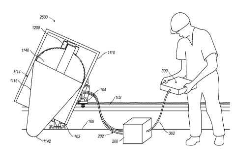
In another embodiment illustrated in FIGS. 26A, 26B, and 27-30, a chain bar
unit 2600 is
illustrated. The chain bar unit 2600 can be implemented with the above
described wall saw 100
and used in place of the chain saw assembly housing 150 described earlier. The
function of the
wall saw 100 can be the same or similar to that of the wall saw as described
above, except that
the chain bar unit 2600 is used for driving the chain or wire around the chain
bar 1116. The
tensioning mechanism described earlier could possibly be included. In at least
one embodiment,
the chain bar unit 2600 can be adapted for removable installation on the saw
arm 112. As the
chain bar unit 2600 can be removably installed on the saw arm 112, the chain
bar unit 2600 can
be easily removed for repair, for storage, and for transport. Furthermore, as
the chain bar unit
2600 can be removably installed on the saw arm 112, the chain bar unit 2600
can be
interchanged with various wall saw assemblies, and preferably with a circular
saw blade, as
described earlier.
For example, as illustrated in FIG. 26A, the wall saw 100 can include a safety
cover and a safety
cover anchor mechanism 108 which is coupled to the carriage 104. The safety
cover anchor
mechanism 108 allows the safety cover 1110 to be attached to the saw via a
retention member
401. The safety cover 1110 can be adapted to accommodate the chain bar unit
2600. The
retention member 401 allows the safety cover 1110 to rotate or turn with
respect to the safety
cover anchor mechanism 108. In the illustrated example, the saw motor 106 is
coupled to a saw
arm 112, which in turn is coupled to the chain bar 1116. The chain bar 1116 is
adjustably
mounted to a chain bar unit 2600, which is slidably connected to the safety
cover 1110 via guides
1114. Therefore the safety cover 1110 and the connected chain bar unit 2600
together form a
chain bar guiding system 2610 for the chain saw, providing numerous advantages
compared to
previous chain bar guiding systems. If for instance the saw arm 112 is turned
slightly anti
clockwise from the position shown in FIG. 26A the safety cover 1110 will turn
slightly
clockwise around the affixment mechanism 109 and the chain bar unit 2600 with
saw bar 1116
CA 02822290 2013-07-19
WO 2012/105904
PCT/SE2012/050104
24
will slide slightly downwards within the safety cover 1110. The retention
member 401 is located
at or near an outer end of the safety cover, i.e. away from the cut, while the
guides 1114 are
arranged to be able to guide the chain bar unit 2600 essentially all the way
to an inner or cutting
end of the safety cover 1110. This design enables the saw bar 1116 to be
essentially fully
withdrawn into the safety cover and be in a vertical position, or the saw bar
to be in a further out
or far out position, as described above and illustrated in relation to other
embodiments in FIGS.
20 and 22, respectively. The safety cover 1110 is of course always perfectly
in line with the saw
bar, enabling the width of the cover to be only somewhat wider than the saw
bar itself Without
this design a much wider, heavier and more costly safety cover would have been
needed, very
similar to a conventional wall saw safety cover. Further this design makes the
chain bar unit
2600 to automatically be turned more than 90 degrees in relation to the outer
end of the saw arm
112 during the cut.
As illustrated in FIGS. 26A and 26B, the chain bar unit 2600 can be coupled to
a saw arm 112.
For example, the chain bar unit 2600 can be rotatably coupled to the saw arm
112. The chain bar
unit 2600 can be slidably connected to the safety cover 1110 to slide when the
saw arm 112 is
pivoted. Thus, when the saw arm 112 is in a starting position where the saw
arm 112 is not
pivoted, the safety cover 1110 can cover a majority of the chain bar unit
2600, thereby protecting
the operator of the wall saw assembly 100 from injuring himself Then, when the
saw arm is
pivoted, as shown in FIGS. 26A and 26B, the distal end 2605 of the bar 1116 of
the chain bar
unit can be at least partially exposed from the safety cover 1110 to engage a
surface to be cut.
Other features of the safety cover 1110 can be similar to those as described
above. The safety
cover illustrated in FIG. 26A has been adapted to accommodate the chain bar
unit 2600 which
will be described in more detail below.
The chain bar unit 2600 includes a bar 1116 that can be configured to accept a
circulating chain
(not shown) around a perimeter of the bar 1116. The bar 1116 can also be
configured to accept a
wire, a cutting line, a cutting chain a chain belt, a chain band, or any other
looped cutting
member which can be received by the bar 1116 and which can circulate around
the bar 1116
during cutting operations.
CA 02822290 2013-07-19
WO 2012/105904
PCT/SE2012/050104
The chain bar unit 2600 can include a driving gear 1140 for driving the chain
(or wire, cutting
line, etc.) around the bar 1116. The driving gear 1140 can be configured to
have the appropriate
receiving surfaces for engagement with the chain, wire, cutting, line. The
driving gear 1140 can
5 be configured to be coupled to an output shaft 372, for example as shown
Fig. 5 (as described
above) of the wall saw 100. In other embodiments, the driving gear 1140 can be
coupled to the
output shaft in other configurations such as a mating engagement, a geared
engagement, a press
fit engagement, or a fastened connection. The output shaft 372 as described
above can be
configured for engagement with the driving gear 1140. In such an embodiment,
the driving gear
10 1140 can receive the rotational output of the output shaft to circulate
the chain around the
perimeter of the bar 1116. In other words, the driving gear 1140 can impart a
force on the chain
to drive circulate the chain about the driven gear 1142 and the bar 1116.
FIG. 26B illustrates another example of the chain bar unit 2600. The chain bar
unit 2600 can
include the safety cover and retention mechanisms as described above, some of
which are
15 omitted for clarity. In other embodiments, the safety cover 1110 can be
implemented with a
differently configured safety cover 1110. The safety cover 1110 can for
instance be integrally
mounted with the chain bar unit 2600. The safety cover 1110 can be configured
to substantially
cover the chain bar 1116 when the chain bar 1116 is not within the material to
be cut. As shown
in FIG. 26B, the driving gear 1140 is substantially larger than the driving
gear 1140 of FIG. 26A.
20 Some further examples of the driving gear 1140 will be described below.
As illustrated in FIG. 27, the bar 1116 is illustrated without one of the
sides of the bar. A further
illustration of the construction of the bar 1116 will be given in relation to
FIG. 31, below. The
bar 1116 can be tapered. For example, the bar 1116 can be tapered from an end
2610 proximate
to the driving gear 1140 to a distal end 2605. The distal end 2605 can have a
distal end radius
25 2615 which can serve as a parameter for determining the size and
placement of the bar 1116,
drive gear 1140, or other element of the chain bar unit 2600. For example, a
width 2620 of the
bar 1116 at the proximate end 2610 can be at least two times the distal end
radius 2615 of the
distal end 2605. In at least one other embodiment, the width 2620 of the bar
1116 at the
proximate end 2610 can be at least three times the distal end radius 2615 of
the distal end 2605.
In another embodiment, the width 2620 of the bar 1116 at the proximate end
2610 can be at least
CA 02822290 2013-11-29
26
four times the distal end radius 2615 of the distal end 2605. In yet another
embodiment, the
width 2620 of the bar 1116 at the proximate end 2610 can be at least five
times the distal end
radius 2615 of the distal end 2605. In still another embodiment, the width
2620 of the bar 1116
at the proximate end 2610 can be at least six times the distal end radius 2615
of the distal end
2605. In yet another embodiment, the width 2620 of the bar 1116 at the
proximate end 2610 can
be at least eight times the distal end radius 2615 of the distal end 2605, or
any other ratio where
the width 2620 of the bar 1116 is larger than the distal end radius 2615 of
the distal end 2605.
Also illustrated in Figure 27, the chain bar unit 2600 can include a driven
gear 1142. The driven
gear 1142 can be located at the distal end 2605 of the bar 1116. The chain can
circulate about
the driven gear 1142 in response to a motive force imparted by the driving
gear 1140. For
example, the driving gear 1140 can be configured directly coupled to the
output shaft of the wall
saw 100. Therefore, the driving gear 1140 can receive a rotational output of
the wall saw 100
and in response can impart a force on the driven gear 1142. For example, as
the driving gear
1140 rotates, the driven gear 1142 will also rotate. In Figure 26, the chain
can couple the driving
gear 1140 to the driven gear 1142, such that as the driving gear rotates 1140,
the chain circulates
around the driving gear 1140 and correspondingly pulls or imparts a motive
force on the driven
gear 1142 to rotate the driven gear 1142.
Additionally, in FIG. 27, the driving gear 1140 can have a diameter (D1) that
is larger than the
diameter (D2) of the driven gear 1142. As the diameter D1 of the driving gear
1140 is greater
than the diameter (D2) of the driven gear 1114, and they are coupled to each
other for example
by a chain. Thus, the driving gear 1140 will rotate at a lower revolution per
minute as compared
to the corresponding speed of the driven gear 1142. The larger size of the
driving gear 1140 will
give an increased peripheral speed of the driven gear 1142 and the chain
coupled to the bar 1116
to be moved at a desired speed. In FIG. 27, the diameter (D1) of the driving
gear 1140 can be at
least two times the diameter (D2) of the driven gear 1142. In at least one
embodiment, the
diameter (D1) of the driving gear 1140 can be at least three times and
preferably at least four
times the diameter (D2) of the driven gear 1142, or any other ratio that
allows the diameter (D1)
to be greater than the diameter (D2) of the driven gear 1142. For example, in
FIG. 26, as the
diameter (D1) of the driving gear 1140 is greater than the diameter (D2) of
the driven gear 1142,
the resulting speed of the chain around the distal end 2605 of the bar 1116
can be at least twenty
CA 02822290 2013-07-19
WO 2012/105904
PCT/SE2012/050104
27
meters per second. In another embodiment, the resulting speed of the chain
around the distal end
2605 of the bar 1116 can be at least twenty-five meters per second. In yet
another embodiment,
the resulting speed of the chain around the distal end 2605 of the bar 1116
can be at least thirty-
five meters per second, or any other speed.
Additionally, as illustrated in FIG. 27, the chain bar unit 2600 can include a
chain bar coupling
device 1200. The chain bar coupling device 1200 can be configured to retain a
first and second
side portions of the bar 1116 together. Additionally, the chain bar coupling
device 1200 can
include a mounting mechanism for the driving gear 1140.
FIG. 28 illustrates a rear view of the chain bar unit 2600. The rear side of
the chain bar unit
2600 is configured for engagement with the saw arm 112. The chain bar unit
2600 can include a
chain bar coupling device 1200 which includes a coupling mechanism 1300 on the
rear face that
abuts the saw arm 112. The coupling mechanism 1300 includes a face plate 1306
and a side
engagement portion 1302. Furthermore, there is a coupling connection 1304 on
the rear side of
the driving gear 1140 for coupling the driving gear 1140 to the output shaft
of the saw arm 112.
FIG. 29 illustrates a side profile view of the coupling mechanism 1300 and the
driving gear
1140. As described above, the coupling mechanism 1300 includes a face plate
1306 and a side
engagement portion 1302.
FIGS. 30 and 31 illustrate the chain bar coupling device 1200. As shown,
coupling device can
be coupled or integrally formed on chain bar 1116. The chain bar coupling
device 1200 can be
configured to couple the first side portion 1117 to the second side portion
1115. The chain bar
coupling device 1200 can comprise and elongate portion 1202. The elongate
portion 1202 can
be configured to engage with a chain bar coupling device receiving portion of
the second side
portion 1115 so that the rotation of the second side portion 1115 resists
rotation relative to the
first side portion 1117. The chain bar coupling device 1200 can further
include an end portion
1204. The end portion 1204 can have a semi-circular shape to further resist
motion of the second
side portion 115 relative to the first side portion 1117.
As illustrated in FIGS. 30-31, a majority of the driving gear 1140 can be
located between the
first side portion 1117 of the bar 1116 and the second side portion 1115 of
the bar 1116. In
another embodiment, the driving gear 1140 can be at least partially located
between the first side
CA 02822290 2014-03-20
28
portion 1117 and the second side portion 1115 of the bar 1116. In yet another
embodiment, at
least a portion of the driving gear 1140 can be located between the first side
portion 1117 of the
bar 1116 and the second side portion 1115 of the bar 1116.
Those of ordinary skill in the art will appreciate that the components of the
wall saw assembly
.;
described in relation to FIGS. 1-25 can be optionally included in the wall saw
assembly
described in FIGS. 26-31.
Having thus described several exemplary implementations, it will be apparent
that various
alterations and modifications can be made without departing from the concepts
discussed herein.
The scope of protection being sought is defined by the following claims rather
than the described
embodiments in the foregoing description. The scope of the claims should not
be limited by the
embodiments set forth in , the description, but should be given the broadest
interpretation
consistent with the description as a whole.