Note: Descriptions are shown in the official language in which they were submitted.
CA 02822488 2013-06-20
WO 2012/083411 - 1 -
PCT/CA2011/000277
VEHICLE CLUTCH CONTROL METHOD
CROSS-REFERENCE
[0001] The present application claims priority to United States
Provisional
Patent Application No. 61/426,846, filed December 23, 2010, the entirety of
which is
incorporated herein by reference.
FIELD OF THE INVENTION
[0002] The present invention relates to a method of controlling a
clutch for a
vehicle and to vehicles having a clutch.
BACKGROUND
[0003] Many motorized wheeled vehicles use one or more clutches to engage
and disengage the engine from the transmission when shifting gears. In some
cases to
control the transfer of torque from the engine to the transmission and/or to
the wheels.
[0004] One type of commonly used clutch it the multi-plate clutch in
which
alternating driving and driven plates are compressed together to transmit
torque from
the engine. To control the activation of such a clutch, a clutch controller
typically
compares the speed of rotation of the driving plates, which can obtained from
the
engine for example, to the speed of rotation of the driven plates, which can
be
obtained from the speed of rotation of a driveshaft connected to one or more
wheels
for example. By comparing these speeds of rotation, the controller can
determine if
the clutch is slipping (i.e. the speed of rotation of the driving plates is
different from
the speed of rotation of the driven plates), or is synchronized (i.e. the
speeds of
rotation of the driving and driven plates are the same), and can make
adjustments
accordingly.
[0005] While this clutch control method is suitable, since the
controller relies
on a clutch output (i.e. the speed of rotation of the driven plates) to
control the clutch,
there is an inherent delay in the controller's response.
[0006] Therefore, there is a need for a clutch control method with
improved
controller response.
CA 02822488 2013-06-20
WO 2012/083411 - 2
PCT/CA2011/000277
-
[0007] The clutch controller usually uses one or more algorithms
and/or
control maps to control the clutch. These algorithms and maps are based on a
desired
performance characteristic for the hardware being used, such as the type of
clutch.
Since the same algorithms and maps are used for multiple vehicles of the same
model,
in order to keep performance and response levels the same for all these
vehicles,
manufacturing tolerances need to be small. For example, in order for the
clutches
being used in the vehicles to provide the same response, when assembling a
clutch,
once all of the driving and driven plates but one have been assembled, the
thickness of
the stack of plates is measured, and the last plate is selected from plates of
different
thicknesses such that once the last plate is assembled, the overall thickness
of the
stack of plates corresponds to the desired stack thickness. As would be
understood,
this is time consuming and complicates the manufacturing process of the
clutch.
[0008] Also, should a user replace a piece of hardware with one which
is
different from the one originally provided by the original manufacturer, the
performance is likely to be affected as the algorithms and maps were not
designed for
this particular piece of hardware. Examples of this include replacing a clutch
with a
similar clutch but from an aftermarket manufacturer due to wear or damage of
the
original clutch, or in the case of a hydraulically actuated clutch, changing
the type of
fluid used to actuate and/or lubricate the clutch could also affect
performance.
[0009] Additionally, should the manufacturer want to use the same hardware
across different models but provide these models with different performance
characteristics, then completely new algorithms and maps need to be developed.
[0010] Also, with use, the hardware, such as the clutch, wears down,
but the
controller does not take into account these changes which can also affect
performance.
[0011] Therefore, there is a need for a clutch control system which is less
sensitive to variations resulting from manufacturing processes, simplifies
modifications to be made to the algorithms and maps necessary to take into
account
changes in desired performance level and hardware, and can take into account
normal
wear of the components.
[0012] Wheeled vehicles having a manual transmission such as some cars
typically used normally closed clutches where one or more springs cause
compression
CA 02822488 2013-06-20
WO 2012/083411- 3 -
PCT/CA2011/000277
of the driving and driven plates together. As such, normally closed clutches
transmit
torque even when no actuation power is provided. Wheeled vehicles having an
automatic transmission such as some cars use a torque converter as a device to
execute takeoff. As a result, when the car is in gear (i.e. not in neutral),
when the
driver does not actuate the accelerator pedal and also does not actuate the
brake pedal,
the car will nonetheless move forward since the the torque converter transmits
a
residual torque to the wheels. This is sometimes referred to as vehicle creep.
However, in some types of vehicles, such as motorcycles for example, vehicle
creep is
not desired. One solution consists in using a normally opened clutch where one
or
more springs cause the driving and driven plates to be normally spaced apart.
Although this eliminates creep, it causes a lag in the actuation of the clutch
when the
driver needs torque to be transmitted to the wheels.
[0013] Therefore, there is a need for a clutch control method which
reduces
the above-mentioned lag resulting from the use of a normally opened clutch.
[0014] Finally, in hydraulically actuated clutches the pressure of the
hydraulic
fluid supplied to the clutch determines if the driving and driven clutch
plates are
slipping relative to one another or are synchronized. However, for a given
method of
controlling the clutch's hydraulic fluid supply system, different hydraulic
fluid
viscosities will result in different hydraulic fluid pressures being supplied
to the
clutch, thus resulting in different performances. One of the factors affecting
hydraulic
fluid viscosity is the temperature of the hydraulic fluid.
[0015] Therefore, there is a need for method of controlling a clutch
which
accounts for variations in temperature of the hydraulic fluid.
SUMMARY
[0016] It is an object of the present invention to ameliorate at least some
of the
inconveniences present in the prior art.
[0017] The present provides a method of controlling a hydraulically
controlled
multi-plate clutch based at least in part on the engine torque. As the engine
torque is
an input to the clutch, the clutch controller using the engine torque as input
to the
CA 02822488 2013-06-20
WO 2012/083411- 4 -
PCT/CA2011/000277
control of the clutch can react more quickly to changes of conditions
requiring
modification of the transmitted clutch torque.
[0018] The present also provides a control system for operating a
hydraulically controlled multi-plate clutch which separates the control of the
clutch in
two portions. The first portion consists of a vehicle behaviour controller.
The vehicle
behaviour controller determines the desired clutch torque (i.e. the torque
output of the
clutch) based at least on the engine torque, independently of the type of
hardware
(clutch, valves, etc.) being used. The second portion consists of a hydraulic
pressure
controller. The hydraulic pressure controller includes one or more
mathematical
models and/or maps based one the hardware being used. For example, there could
be
a model for the clutch and a model for the valve used in the hydraulic fluid
supply
system. The hydraulic pressure controller takes the desired clutch torque as
input to
the models and/or maps and determines how the hydraulic fluid system should be
controlled in order to obtain the desired clutch torque from the clutch.
[0019] By separating the control in two portions as described above, when
the
same vehicle behaviour is desired but for different hardware, only the
hydraulic
pressure controller needs to be modified or only one or more models and/or
maps
need to be modified. For example, if two different vehicle models use
different
clutches, but the same vehicle behaviour is desired for both models, then only
the
mathematical model of the clutch used in the hydraulic system controller need
to be
changed.
[0020] Similarly, when the same hardware is being used in two
different
vehicle models, such as a touring and a sport model for example, but different
vehicle
behaviours are desired for the two models, then only the vehicle behaviour
controller
needs to be modified and the hydraulic pressure controller can remain the same
for
both models
[0021] In order to account for the wear of the components or for the
change of
components after initial manufacturing, the hydraulic pressure controller is
provided
with adaptation components which compare the actual outputs from the hardware,
clutch and hydraulic pressure for example, to the desired outputs from the
hardware.
Should there be a difference between the desired and actual outputs, then the
CA 02822488 2013-06-20
WO 2012/083411 - 5
PCT/CA2011/000277
-
adaptation components update the various models and/or maps such that the
difference is eliminated, or at least reduced. The adaptation components are
also used
to adapt the models and/or maps, which are initially designed for a component
(i.e.
clutch, valve...) having specific characteristics, to match the specific
characteristics of
the component installed in the vehicle. As such, the adaptation components
will take
into account variations resulting from manufacturing tolerances, such that
even if
components installed into two different vehicles are not perfectly identical,
the
controller will ensure that their performance is identical. As a result,
manufacturing
tolerances of the components do not need to be as tight and they do not need
to be
corrected as described above (i.e. by the measurement of the clutch plate
stack for
example).
[0022] In a similar manner, the hydraulic pressure controller
accounts for
variations in temperature of the hydraulic fluid by reducing the hydraulic
pressure
being applied to the clutch as the temperature of the hydraulic fluid
decreases.
[0023] The present also provides a method of controlling a normally opened
hydraulically controlled multi-plate clutch in order to reduce the above-
mentioned lag
in actuation of the clutch. As the clutch is biased to a normally opened
position by a
spring, it is possible to establish a correlation between the pressure being
applied to
the clutch and a displacement of a clutch piston. By knowing this correlation
it is
possible to know the amount of pressure necessary to bring the piston to a
position
corresponding to the clutch kiss-point or a position near the clutch kiss-
point. The
clutch kiss-point is the point at which the clutch driving and driven plates
start
touching each other. When the engine is running but the vehicle is not in
movement,
the method controls the pressure supplied to the clutch such that the clutch
is at or
near the clutch kiss-point. Therefore, when the driver operates the vehicle so
as to
initiate movement of the vehicle, very little displacement of the clutch
piston is
necessary to engage the clutch driving and driven plates to transmit torque
from one
to the other, and the response time between the driver input and the
transmission of
torque to the wheels is short.
[0024] The present also provides a vehicle using a clutch control method
and
system as described above.
CA 02822488 2013-06-20
WO 2012/083411-
PCT/CA2011/000277
- 6
[0025] The present provides a vehicle having an engine having a
crankshaft, a
hydraulically controlled multi-plate clutch operatively connected to the
crankshaft,
and an output shaft operatively connected to the clutch. The clutch
selectively
transmits power from the crankshaft to the output shaft. A propulsion element
is
operatively connected to the output shaft. A hydraulic fluid supply system is
fluidly
connected to the clutch for supplying pressurized hydraulic fluid to the
clutch. A
controller is connected to the hydraulic fluid supply system. The controller
receives a
torque signal indicative of engine torque and controls the hydraulic fluid
supply
system based at least in part on the torque signal.
[0026] The present also provides a method of operating a hydraulically
controlled multi-plate clutch selectively transmitting torque from an engine
of a
vehicle to a propulsion element of the vehicle. The method comprises:
determining
an engine torque; determining a clutch torque to be transferred by the clutch
based at
least in part on the engine torque; determining a hydraulic pressure to be
applied to
the clutch based on the clutch torque; and applying the hydraulic pressure to
the
clutch.
[0027] The present also provides a control system for operating a
hydraulically controlled multi-plate clutch selectively transmitting torque
from an
engine of a vehicle to a propulsion element of the vehicle. The system has a
vehicle
behaviour controller determining a desired clutch torque to be applied to the
clutch
based at least in part on engine torque; and a hydraulic pressure controller
determining
a control signal to be sent to a hydraulic fluid supply system to control the
hydraulic
fluid supply system to supply hydraulic fluid to the clutch at a pressure
resulting in the
desired clutch torque being provided by the clutch. The hydraulic fluid supply
system
includes a hydraulic fluid pump and a valve. The control signal is determined
based
on the desired clutch torque and an inverse model of at least one of the
clutch and the
valve.
[0028] Embodiments of the present invention each have at least one of
the
above-mentioned features, but do not necessarily have all of them. It should
be
understood that some aspects of the present invention may satisfy objects not
specifically recited herein.
CA 02822488 2013-06-20
WO 2012/083411- 7 -
PCT/CA2011/000277
[0029] Additional and/or alternative features, aspects, and
advantages of
embodiments of the present invention will become apparent from the following
description, the accompanying drawings, and the appended claims.
BRIEF DESCRIPTION OF THE DRAWINGS
[0030] For a better understanding of the present invention, as well as
other
aspects and further features thereof, reference is made to the following
description
which is to be used in conjunction with the accompanying drawings, where:
[0031] Figure 1 is a perspective view taken from a front, left side
of a three-
wheel vehicle;
[0032] Figure 2 is a right side elevation view thereof;
[0033] Figure 3 is a top elevation view thereof;
[0034] Figure 4 is a schematic representation of a drive train of the
vehicle of
Fig. 1;
[0035] Figure 5 is a schematic representation of a hydraulic fluid
supply
system for a clutch of the vehicle of Fig. 1;
[0036] Figure 6 is a cross-sectional view of the clutch of the
vehicle of Fig. 1;
[0037] Figure 7 is a logic diagram illustrating a clutch control
map/mode
selection method;
[0038] Figure 8 is a graphical representation of a relationship
between
hydraulic pressure applied to the clutch and a position of a piston of the
clutch used
during a pre-launch mode;
[0039] Figure 9 illustrates a launch map;
[0040] Figure 10 illustrates a synchronized map;
[0041] Figures 11A to 11 C illustrate changes over time of the
throttle
position, engine speed and vehicle speed respectively;
CA 02822488 2013-06-20
WO 2012/083411- 8 -
PCT/CA2011/000277
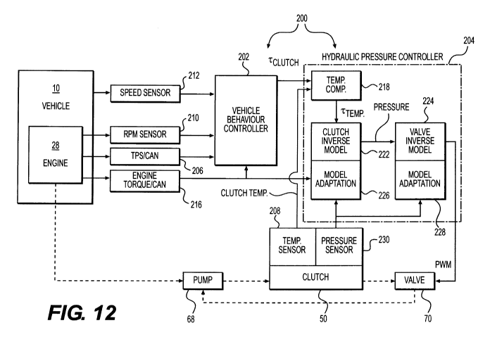
[0042] Figure 12 is a schematic representation of a clutch control
system; and
[0043] Figure 13 is a graphical representation of a clutch torque
correction in
function of hydraulic fluid temperature.
DETAILED DESCRIPTION
[0044] The present invention will be described with respect to a three-
wheel
vehicle. However, it should be understood that other types of vehicles such
as, for
example, road and off-road motorcycles, four-wheel all-terrain vehicles and
snowmobiles are also considered.
[0045] A three-wheel vehicle 10 will be described with reference to
Figs. 1 to
3. The three-wheel vehicle 10 is a straddle-type vehicle comprising a straddle
seat 12
adapted to accommodate two adult sized riders. The straddle seat 12 includes a
forward seat portion 14 for the driver and a rear seat portion 16 for a
passenger. A
pair of handles 18 are provided on both sides of the rear seat segment 16 for
the
passenger sitting thereon to grip with his hands. A pair of foot pegs 20 and a
pair of
foot pegs 22 are used by the driver and the passenger respectively, for
resting their
feet onto during riding. It is contemplated that the three-wheel vehicle 10
could not
have the rear seat portion 16, and be adapted to accommodate only the driver
and that
accordingly the three-wheel vehicle 10 would not have the handles 18 and would
have
only the pair of foot pegs 20.
[0046] The three-wheel vehicle 10 includes a frame 24 (a portion of which
is
shown in Fig. 2) underneath the body panels 26 of the vehicle 10. The frame 24
supports and houses an engine 28 (schematically shown in Fig. 2). The engine
28 is a
four-stroke internal combustion engine, but other types of engines are
contemplated.
A single rear wheel 30 with a tire suitable for road use is suspended from the
vehicle
10 via a rear suspension system 32 (Fig. 2) at the rear of the frame 24. A
pair of front
wheels 34 are suspended from the front of the frame 24 through a suitable
suspension
assembly 36 such as a double A-arm suspension assembly. The front wheels 34
have
road tires mounted thereon.
[0047] A steering assembly 38 is coupled to the front wheels 34 and
is
supported by the frame 24 for transmitting steering commands to the front
wheels 34.
CA 02822488 2013-06-20
WO 2012/083411- 9 -
PCT/CA2011/000277
The steering assembly 38 includes a steering column (not shown) and a
handlebar 40.
A throttle lever 41 (Fig. 2) is disposed at one end of the handlebar 40 to
allow the
driver to control a speed of the vehicle 10. A windshield 42 is mounted
forwardly of
the handlebar 40. A pair of rear view mirrors 44 are mounted on either side of
the
windshield 42. A dashboard 46 is disposed between the handlebar 40 and the
windshield 42.
[0048] The three-wheel vehicle 10 is provided with many other
components
and features which would be known to a person skilled in the art such as a
fuel
system, an exhaust system, a lubrication system, head and tail lights. As such
these
components and features will not be described herein in detail. However, it
should be
understood that the vehicle 10 is nonetheless provided with such components
and
features.
[0049] Turning now to Fig. 4, a drive train of the vehicle 10 will be
described.
The engine 28 drives a hydraulically controlled multi-plate clutch 50. The
clutch will
be described in more detail further below. The clutch 50 selectively transmits
torque
from the engine 28 to a transmission 52 of the vehicle 10. The transmission 52
is a
semi-automatic transmission, but it is contemplated that an automatic
transmission
could be used. It is contemplated that the clutch 50 could be integrally
formed with
the engine 28 or the transmission 52. The transmission 52 drives a driving
sprocket
54. The driving sprocket 54 drives a driven sprocket 56 via a chain or belt
58. The
driven sprocket 56 drives the rear wheel 30. It is contemplated that the
transmission
52 could be omitted and the clutch 50 could be connected directly to the
driving
sprocket 54. As should be understood, in different types of vehicles the
engine 28
would drive the wheel(s) or other propulsion element, such as the track in a
snowmobile, through a suitable drive train.
[0050] As mentioned above, the clutch 50 is a hydraulically driven
multi-plate
clutch 50. As such, the clutch 50 is engaged and disengaged by applying
hydraulic
pressure to a piston 60 of the clutch 50. The clutch 50 is a normally opened
clutch 50,
which means that when no, or only a small amount of pressure is applied, the
clutch
50 is disengaged. Springs 62 bias the clutch toward the disengaged (i.e. open)
position. When hydraulic pressure is applied, the piston 60 pushes the plates
of the
CA 02822488 2013-06-20
WO 2012/083411- 10 -
PCT/CA2011/000277
clutch 50 together, as described in greater detail below, thus causing the
clutch 50 to
transmit torque from the engine 28 to the transmission 52.
[0051] To supply hydraulic pressure to the clutch 50, a hydraulic
fluid supply
system 64 is provided. The hydraulic fluid supply system 64 is schematically
illustrated in Fig. 5. The hydraulic fluid supply system 64 includes a
hydraulic fluid
reservoir 66, a hydraulic fluid pump 68, and a valve 70. The hydraulic fluid
used in
the present embodiment to actuate and lubricate the clutch 50 is the oil used
to
lubricate the engine 28. As such the hydraulic fluid reservoir 66 is the oil
tank of the
engine 28. However, it is contemplated that the hydraulic fluid system 64
could be
completely independent of the lubrication system of the engine 28 and use a
hydraulic
fluid other than engine lubricant to both actuate and lubricate the clutch 50.
It is also
contempated that the hydraulic fluid system 64 could be completely independent
of
the lubrication system of the engine 28 and use a hydraulic fluid other than
engine
lubricant to actuate the clutch 50, and that the engine lubricant or another
lubricating
fluid (and an associated lubricant distribution system) would be used to
lubricate the
clutch 50. The pump 68 is an electrical pump, however it is contemplated that
the
pump 68 could be a different type of pump, such as a mechanical pump driven by
the
engine 28. The pump 68 continuously pumps hydraulic fluid from the reservoir
66 to
the clutch 50. As hydraulic fluid is being supplied to the clutch 50 the
pressure
therein increases thus causing the piston 60 to overcome the bias of the
spring 62
eventually causing the clutch 50 to become engaged so as to transmit torque
from the
engine 28 to the transmission 52. Opening the valve 70 relieves the pressure
inside
the clutch 50 and allows fluid to return to the reservoir 66 or the pump 68.
Therefore,
by controlling an opening and closing cycle of the valve 68 it is possible to
control the
hydraulic pressure inside the clutch 50. Since the spring constant of the
springs 62 is
known, it is therefore possible to control a position of the piston 60 of the
clutch 50 as
will be described in greater detail below. The valve 70 is an electrically
controlled
valve. The opening and closing cycle of the valve 70 is determined by a
controller
200, discussed in greater detail below, which sends a pulse-width modulated
(PWM)
signal to the valve 70. It is contemplated that the valve 70 could be disposed
between
the pump 68 and the clutch 50 so as to selectively fluidly communicate the
pump 68
with the clutch 50. It is also contemplated that the pump 68 could be a
variable
displacement pump, in which case it may be possible to eliminate the valve 70
and the
CA 02822488 2013-06-20
W02012/08341111 -
PCT/CA2011/000277
-
hydraulic pressure inside the clutch 68 is effected by varying the
displacement of the
pump 68.
[0052] Turning now to Fig. 6, the clutch 50 will be described in more
detail.
The clutch 50 is driven by a crankshaft 72 of the engine 28. The crankshaft 72
has a
gear 74 thereon which engages a ring gear 76 of the clutch 50. The ring gear
76 is
fastened to a clutch drum 78 which rotates therewith. The clutch drum 78
receives
therein a plurality of driving clutch plates 80. The driving clutch plates 80
are splined
to the clutch drum 78 so as to rotate therewith, but can translate along the
rotational
axis 82 of the clutch 50. Driven clutch plates 84 are disposed inside the
clutch drum
78 such that each driving clutch plate 80 is received between two driven
clutch plates
84. The driven clutch plates 84 are splined onto a rotor 86 so as to transfer
rotational
motion to the rotor 86 when the clutch 50 is engaged. The clutch plates 84 can
translate along the rotational axis 82. The rotor 86 does not move along the
rotational
axis 82. The rotor 86 is splined onto an output shaft 88 thus causing the
output shaft
88 to rotate when the clutch 50 is engaged, thereby transferring torque from
the
engine 28 to the transmission 52.
[0053] A cover 90 is fastened to the rotor 86 so as to rotate
therewith. An end
plate 92 is mounted to the end of the output shaft 88 and rotates therewith.
It is
contemplated that the end plate could be omitted or integrally formed with the
output
shaft 88. The piston 60 is housed in the space formed between the cover 90,
the rotor
86 and the end plate 92. Four springs 62 (only three of which are shown) are
disposed
between the end plate 92 and the piston 60. The springs 92 are coil springs,
but it is
contemplated that other types of springs could be used. It is also
contemplated that
more or less than four springs 62 could be used. The springs 62 bias the
piston 60
away from the end plate 92 (i.e. toward the right in Fig. 6). A variable
volume
chamber 94 is formed between the piston and the cover 90. The piston 60 is
mounted
on a piston rod 96 and can translate along the rotational axis 82. The piston
60 abuts
and selectively applies pressure to a pusher plate 98 which in turn
selectively applies
pressure to the clutch plates 80, 84 as will be described in greater detail
below.
[0054] Hydraulic fluid is supplied by the pump 68 via the clutch fluid
inlet
100 and flows to the chamber 94. As discussed above, by opening and closing
the
valve 70, the hydraulic pressure in the chamber 94 can be controlled.
Hydraulic fluid
CA 02822488 2013-06-20
WO 2012/083411- -
PCT/CA2011/000277
12
going to the valve 70 passes via the clutch fluid outlet 102. In case the
hydraulic
pressure inside the clutch 50 becomes too high, due to a failure of the valve
70 for
example, a pressure relief valve 104 opens to prevent damage to the clutch 50
and/or
the hydraulic fluid supply system 64. As the hydraulic pressure inside the
chamber 94
is increased, the force applied to the piston 60 by the hydraulic fluid
overcomes the
bias of the springs 62 and the piston translates toward the end plate 92 (i.e.
toward the
left in Fig. 6). As the piston 60 translates, it moves the pusher plate 98 in
the same
direction. Fig. 8 illustrates the relationship between the hydraulic pressure
inside the
chamber 94 and the distance of the piston 60 to the clutch kiss-point (KP in
Fig. 8).
This relationship is used in the pre-launch mode 110. The clutch kiss-point is
the
point at which the clutch driving and driven plates 80, 84 start touching each
other as
a result of the pusher plate 98 pressing on the plates 80, 84. As can be seen
in Fig. 8,
until the piston 60 reaches the clutch kiss-point, the clutch 50 is disengaged
and the
relationship between the pressure in the chamber 94 and the position of the
piston 60
is linear as a result of the linear response of the springs 62 being
compressed (F=kx).
Once the piston 60 reaches the clutch kiss-point, applying further pressure
will result
the clutch plates 80, 84 being compressed between the pusher plate 98 and the
rotor
86, thus engaging the clutch 50, and transmitting rotational motion and torque
from
the driving clutch plates 80 to the driven clutch plates 84. As a result, the
driven
clutch plates 84 drive the rotor 86 which drives the output shaft 88. As can
be seen in
Fig. 8, increasing the pressure to the piston 60 once it has reached the
clutch kiss-
point continues to move the piston 60 but at a much slower rate. This
displacement is
a result of the clutch plates 80, 84 being compressed as a result of the
pressure being
applied to them. As would be understood, reducing the hydraulic pressure
inside the
chamber 94 causes the piston 60 and pusher plate 98 in the opposite direction
according to the relationship illustrated in Fig. 8, eventually disengaging
the clutch 50
once the clutch kiss-point is reached.
[0055] The amount of hydraulic pressure to be applied to the clutch
50, and
therefore the amount of torque being transmitted from the engine 28 to the
rear wheel
30 by the clutch 50, is determined by the controller 200 which controls the
opening
and closing cycle of the valve 70. To do this, the controller 200 is divided
into two
controllers as shown in Fig. 12. These are the vehicle behaviour controller
202 and
the hydraulic pressure controller 204. The vehicle behaviour controller 202
uses one
CA 02822488 2013-06-20
WO 2012/083411 - 13 -
PCT/CA2011/000277
of three clutch control maps/modes depending on the operating condition of the
vehicle 10 and engine 28 to determine the clutch torque to be applied by the
clutch 50
(i.e. the torque at the output shaft 88 of the clutch 50). These maps/modes
are
designed to provide a desired vehicle response to inputs by the driver of the
vehicle
10. Depending on the type of vehicle, a more or less aggressive response may
be
desired. These maps/modes are designed independently from the specific
components
(clutch 50, valve 70) being used in the vehicle. The maps/modes are a pre-
launch
mode 110 an example of a relationship used thereby being shown in Fig. 8, a
launch
map 112 an example of which is shown in Fig. 9, and a synchronized map 114 an
example of which is shown in Fig. 10. The clutch control map/mode selection
method 150 used by the behaviour controller 202 will be described below with
respect
to Fig. 7. The hydraulic pressure controller 204 then takes the clutch torque
determined by the behaviour controller 202 and determines the pulse-width
modulated
(PWM) signal to be applied to the valve 70 that will result in the appropriate
hydraulic
pressure being applied to the clutch 50 to obtain the desired clutch torque as
will be
described below with respect to Fig. 12.
[0056] Turning now to Fig. 7, an exemplary embodiment of a clutch
control
map/mode selection method 150 used by the vehicle behaviour controller 202
will be
described. The method 150 will be described in combination with Fig. 12 which
illustrates the clutch control system. The method 150 is initiated at step
152. At step
154, a throttle position sensor 206 senses a position of the throttle lever
41. The
throttle position sensor 204 sends a signal indicative of the throttle
position to the
vehicle behaviour controller 202. In the present embodiment, the throttle
position is
expressed in terms of percentage of actuation of the throttle lever 41 (Th%).
When
the throttle lever 41 is not actuated (Th% = 0), the throttle lever is in what
is known as
an idle position. It is contemplated that the throttle position could be
expressed as
other units, such as angle of rotation of the throttle lever, or could be
expressed as a
unit less value. The throttle position sensor 204 sends the signal indicative
of the
throttle position via a controller area-network (CAN), but it is contemplated
that other
devices and communication protocols could be used.
[0057] At step 156, the vehicle behaviour controller 202 determines
if the
throttle lever 41 is actuated (Th% > 0). If the throttle lever 41 is actuated,
the vehicle
CA 02822488 2013-06-20
WO 2012/083411- 14 -
PCT/CA2011/000277
behaviour controller 202 selects the launch map 112. If at step 156, the
throttle lever
41 is at the idle position (i.e. not actuated, Th% = 0), then the vehicle
behaviour
controller 202 selects the pre-launch mode 110.
[0058] If at step 156, the vehicle behaviour controller 202 selects
the pre-
CA 02822488 2013-06-20
WO 2012/083411- 15 -
PCT/CA2011/000277
supplied to the clutch 50 in order to bring the clutch 50 near the clutch kiss-
point.
From step 160, the method 150 resumes at step 154.
[0059] If at step 156 the vehicle behaviour controller 202 selects
the launch
map 112, then at step 162 the vehicle behaviour controller 202 determines the
input
rotational speed of the clutch 50 (N in), which corresponds to the speed of
rotation of
the driving clutch plates 80. In the present embodiment, the vehicle behaviour
controller 202 does this by receiving a signal from an engine speed sensor 210
sensing
a speed of rotation of the engine 28 (i.e. the speed of rotation of the
crankshaft 72).
Since the ratio of the gears 74 and 76 is known, the vehicle behaviour
controller 202
can derive the input rotational speed of the clutch 50 from the engine speed.
It is
contemplated that the input rotational speed of the clutch 50 could be
determined by
other means, such as by sensing a speed of rotation of the ring gear 76 or
clutch drum
78 directly. Then at step 164 the vehicle behaviour controller 202 determines
the
output rotational speed of the clutch 50 (N out), which corresponds to the
speed of
rotation of the driven clutch plates 84 and of the output shaft 88. In the
present
embodiment, the vehicle behaviour controller 202 does this by receiving a
signal from
a speed sensor 212 sensing a speed of rotation of the shaft 214 (Fig. 4)
driving the rear
wheel 30. Since the ratio of the rotational speeds of the output shaft 88 and
the shaft
214 is known, the vehicle behaviour controller 202 can derive the output
rotational
speed of the clutch 50 from the speed of the shaft 214. It is contemplated
that the
output rotational speed of the clutch 50 could be determined by other means,
such as
by sensing a speed of rotation of the output shaft 88 directly or by sensing a
speed of
rotation of one of the sprockets 54 and 56.
[0060] At step 166, the vehicle behaviour controller 202 then
compares the
input rotational speed of the clutch 50 to the output rotational speed of the
clutch 50
and determines if the difference between these two values is less than a first
predetermined value (X RPM). In an exemplary embodiment, the first
predetermined
value is 50 RPM. If the difference is greater than or equal to the first
predetermined
value, then the vehicle behaviour controller 202 moves to step 168 and
determines the
clutch torque to be applied by the clutch 50 using the launch map 112. The
clutch
torque is determined from the engine torque and the engine speed (engine RPM).
As
shown in Fig. 9, as the engine speed and engine torque increase, the desired
clutch
CA 02822488 2013-06-20
WO 2012/083411- 16 -
PCT/CA2011/000277
torque increases as well. The engine speed is determined by the engine speed
sensor
210 as described above. The engine torque is determined by using an engine
torque
map 216 having engine speed and position of the throttle lever 41 as inputs. A
signal
indicative of the engine torque is sent to the vehicle behaviour controller
202 via
CAN, but it is contemplated that other devices and communication protocols
could be
used. It is contemplated that the engine torque could be determined by any
other
means. For example, instead of using the torque map 216, an engine control
module
or the vehicle behaviour controller 202 could calculate the engine torque from
the
engine speed and the position of the throttle lever 41. In another example,
the engine
torque could be measured using a torque sensor measuring the torque at the
crankshaft 72 of the engine 28. The clutch torque is then entered into the
hydraulic
pressure controller 204 to determine the PWM signal to be applied to the valve
as
described in greater detail below. While the launch map 112 is being used, the
driving clutch plates 80 and the driven clutch plates 84 do not rotate at the
same speed
and slip relative to each other. From step 168, the method 150 resumes at step
154.
[0061] If a step 166 the difference between the input rotational
speed of the
clutch 50 and the output rotational speed of the clutch 50 is less than the
first
predetermined value, then the vehicle behaviour controller 202 selects the
synchronized map 114. Then at step 170, the vehicle behaviour controller 202
compares the input rotational speed of the clutch 50 to the output rotational
speed of
the clutch 50 and determines if the difference between these two values is
greater than
a second predetermined value (Y RPM). In the present embodiment, the second
predetermined value is greater than the first predetermined valued, however it
is
contemplated that they could be the same. In an exemplary embodiment, the
second
predetermined value is 100 RPM. If the difference is less than or equal to the
second
predetermined value, then the vehicle behaviour controller 202 moves to step
172 and
determines the clutch torque to be applied by the clutch 50 using the
synchronized
map 114. The desired clutch torque is determined from the engine torque and
the
engine speed in the same manner as described above with respect to step 168.
As can
be seen in Fig. 10, the synchronized map 114 has two main portions: portion A
and
portion B. In portion A, the clutch torque varies in response to both engine
torque and
engine speed. Also, in portion A, for at least some engine speed and engine
torque
combinations, the driving and driven clutch plates 80, 84 slip relative to
each other.
CA 02822488 2013-06-20
WO 2012/083411- 17 -
PCT/CA2011/000277
In portion B, the clutch torque varies only in response to engine torque. It
is
contemplated however that the clutch torque could also vary in response to
engine
speed in portion B. Also, in portion B, the driving and driven clutch plates
80, 84
rotate at the same speed and are said to be synchronized (hence the name of
map 114).
The clutch torque is then entered into the hydraulic pressure controller 204
to
determine the PWM signal to be applied to the valve as described in greater
detail
below.
[0062] From step 172, the vehicle behaviour controller 202 moves to
step 174
where the vehicle behaviour controller 202 determines the input rotational
speed of
the clutch 50 in the same manner as in step 162 described above. From step
174, the
vehicle behaviour controller 202 moves to step 176 where the vehicle behaviour
controller 202 determines the output rotational speed of the clutch 50 in the
same
manner as in step 164 described above. From step 176, the vehicle behaviour
controller returns to step 170. As would be understood, steps 172 to 176 will
continue
to be repeated, and the desired clutch torque will continue to be determined
using the
synchronized map 114, until the vehicle behaviour controller 202 determines at
step
170 that the difference between the input rotational speed of the clutch 50
and the
output rotational speed of the clutch 50 is greater than the second
predetermined
value.
[0063] If at step 170, the vehicle behaviour controller 202 determines that
the
difference between the input rotational speed of the clutch 50 and the output
rotational
speed of the clutch 50 is greater than the second predetermined value, then
the vehicle
behaviour controller selects the launch map 112 and the method 150 resumes at
step
154.
[0064] Turning now to Figs. 11A to 11C, the change in engine speed over
time (Fig. 11B) resulting from a change in throttle position (Fig. 11A) and
the change
in vehicle speed (Fig. 11C) resulting from the change in throttle position and
change
in engine speed (and therefore of engine torque) using the method 150 of Fig.
7 will
be discussed. As can be seen in Fig. 11C, the vehicle start from rest. During
time
period A, the throttle lever 41 is at the idle position (Th% = 0), the engine
28 is
running at a constant idle speed and the vehicle 10 remains at rest. As such,
during
time period A, the vehicle behaviour controller 202 is in the pre-launch mode
110 and
CA 02822488 2013-06-20
WO 2012/083411
- 18 -
PCT/CA2011/000277
the clutch 50 is set at the clutch kiss-point. Then during time period B, the
throttle
lever 41 is actuated and kept at a constant position as can be seen in Fig.
11A. As can
be seen from Fig. 11 this results in the engine speed increasing non-linearly.
During
time period B, the difference in speed between the input rotational speed of
the clutch
50 and the output rotational speed of the clutch 50 is greater than the first
predetermined value (i.e. X RPM). As such, the vehicle behaviour controller
202
uses the launch map 112. This results in a generally linear increase in the
vehicle
speed. As the engine speed and engine torque increase during the time period
B, the
clutch torque increases, thus reducing the difference in speed between the
input
rotational speed of the clutch 50 and the output rotational speed of the
clutch 50. At
the end of time period B, the difference in speed between the input rotational
speed of
the clutch 50 and the output rotational speed of the clutch 50 is less than
the first
predetermined value and the vehicle behaviour controller 202 switches to the
synchronized map 114. During time period C, the throttle lever 41 is
maintained at
the same position as in time period B, and the engine speed increases
linearly. As a
result of using the synchronized map 114, the vehicle speed continues to
increase.
Figs. 11A to 11C illustrate only one scenario resulting from the use of the
method 150
of Fig. 7 and the maps/modes 110, 112, and 114. It should be understood that
depending on the calibration of the maps/modes 110, 112, and 114, the
resulting
vehicle speed response may be different from the one illustrated in Fig. 11C.
For
example the vehicle speed could not increase linearly in either one or both of
time
periods B and C.
[0065] Turning now to Fig. 12, the hydraulic pressure controller 204
will be
described in more detail. As previously described, the hydraulic pressure
controller
204 takes the desired clutch torque determined as described above by the
vehicle
behaviour controller 202 and determines based on the clutch torque the PWM
signal
to be sent to the valve 70 that will result in the correct hydraulic pressure
being
applied to the clutch 50 to obtain this clutch torque. The hydraulic pressure
controller
204 includes a hydraulic fluid temperature clutch torque compensation
component
218, a clutch inverse model 222, a valve inverse model 224, and adaptation
components 226, 228 for the models 222 and 224 respectively.
CA 02822488 2013-06-20
WO 2012/083411- 19 -
PCT/CA2011/000277
[0066] As previously described, as the temperature of the hydraulic
fluid
decreases, its viscosity increases and a lower pressure can be applied to the
clutch 50
to obtain the same result as at a higher temperature. Therefore, to take this
into
account, the hydraulic fluid temperature clutch torque compensation component
218
makes a correction to the clutch torque determined by the vehicle behaviour
controller
202 by reducing the clutch torque that will be used to determine the PWM
signal.
Fig. 13 illustrates an exemplary graphical representation 220 of a clutch
torque
correction in function of hydraulic fluid temperature. As can be seen, the
lower the
hydraulic fluid temperature is, the greater is the amount by which the clutch
torque
determined by the vehicle behaviour controller 202 will be reduced (note that
the
torque correction values are negative).
[0067] The corrected clutch torque value obtained from the
compensation
component 218 is then input into the clutch inverse model 222. The clutch
inverse
model 222 is the inverse function of a mathematical representation of the
physical
behaviour of the clutch 50 (i.e. the inverse of a clutch model). The clutch
model can
be obtained through experimentation for example, by determining the clutch
torques
resulting from various hydraulic pressures being supplied to the clutch 50.
The clutch
inverse model 222 is the inverse mathematical function of the clutch model and
as
such allows the hydraulic pressure controller 204 to determine the hydraulic
pressure
to be applied to the clutch 50 to obtain a desired clutch torque. It is
contemplated that
the clutch inverse model 222 could also be in the form of a lookup table or
map.
Therefore, the clutch inverse model 222 determines the hydraulic pressure to
be
supplied to the clutch 50 to obtain the corrected clutch torque value obtained
from the
compensation component 218. The clutch inverse model 222 is associated with
the
adaptation component 226. The adaptation component 226 updates/modifies the
clutch inverse model 222 to take into account changes in the behaviour of the
clutch
50 over time resulting from wear of the clutch 50 and/or to take into account
differences between the clutch 50 being used in the vehicle 10 and the clutch
50 used
to make the clutch inverse model 222 that result from manufacturing tolerance
(i.e.
two clutches of the same model may not behave exactly in the same manner).
Therefore the adaptation component 226 insures that the hydraulic pressure
determined by the clutch inverse model 222 will provide the correct clutch
torque.
The adaptation component 226 uses the engine torque 216 and the actual
hydraulic
CA 02822488 2013-06-20
WO 2012/083411- 2 -
PCT/CA2011/000277
0
pressure in the clutch 50 sensed by a hydraulic pressure sensor 230 to
determine if and
how the clutch inverse model 222 needs to be updated or modified. In an
alternative
embodiment, the adaptation component 226 applies a correction factor to the
pressure
obtained from the clutch inverse model 222 instead of updating or modifying
the
clutch inverse model 222.
[0068] The hydraulic fluid pressure value obtained from the clutch
inverse
model 222 is then input into the valve inverse model 224. The valve inverse
model
224 is the inverse function of a mathematical representation of the physical
behaviour
of the valve 70 operating in combination with the pump 68 and the clutch 50
(i.e. the
inverse of a valve model). The valve model can be obtained through
experimentation
for example, by determining the hydraulic fluid pressure resulting from
various PWM
signals being applied to the valve 70 being used with the clutch 50 and the
pump 68.
The valve inverse model 224 is the inverse mathematical function of the valve
model
and as such allows the hydraulic pressure controller 204 to determine the PWM
signal
to be applied to the valve 70 to obtain a desired hydraulic fluid pressure. It
is
contemplated that the valve inverse model 224 could also be in the form of a
lookup
table or map. Therefore, the valve inverse model 224 determines the PWM signal
to
be applied to the valve 70 to obtain the hydraulic fluid pressure value
obtained from
the clutch inverse model 222. The valve inverse model 224 is associated with
the
adaptation component 228. The adaptation component 228 updates/modifies the
valve inverse model 224 to take into account changes in the behaviour of the
valve 70
(and pump 68) over time resulting from wear of the valve 70 (and pump 68)
and/or to
take into account differences between the valve 70 (and pump 68) being used in
the
vehicle 10 and the valve 70 (and pump 68) used to make the valve inverse model
224
that result from manufacturing tolerance (i.e. two valves/pump of the same
model
may not behave exactly in the same manner). Therefore the adaptation component
228 insures that the PWM signal determined by the valve inverse model 224 will
provide the correct hydraulic fluid pressure to the clutch 50. The adaptation
component 228 uses the actual hydraulic pressure in the clutch 50 sensed by
the
hydraulic pressure sensor 230 and compares it to the desired hydraulic fluid
pressure
determined by the clutch inverse model 222 to determine if and how the valve
inverse
model 224 needs to be updated or modified. In an alternative embodiment, the
adaptation component 228 applies a correction factor to the PWM signal
obtained
CA 02822488 2013-06-20
WO 2012/083411- 21 -
PCT/CA2011/000277
from the valve inverse model 224 instead of updating or modifying the valve
inverse
model 224.
[0069] Modifications and improvements to the above-described
embodiments
of the present invention may become apparent to those skilled in the art. The
foregoing description is intended to be exemplary rather than limiting. The
scope of
the present invention is therefore intended to be limited solely by the scope
of the
appended claims.