Note: Descriptions are shown in the official language in which they were submitted.
CA 02822756 2013-06-21
WO 2012/087892
PCT/US2011/065760
1
METHOD FOR CONTROLLING THE DOWNHOLE TEMPERATURE
DURING FLUID INJECTION INTO OILFIELD WELLS
Field
[0001] The application relates to methods to control the delivery of fluids
for use in
oilfield applications for subterranean formations. More particularly, the
application
relates to controlling the fluid temperature.
Background
[0002] The statements in this section merely provide background information
related
to the present disclosure and may not constitute prior art.
[0003] This application relates to fluids used in treating a subterranean
formation. The
pumping of treatment fluids, such as acids or other types of fluids and
chemicals is
routinely conducted in oil and gas production wells and in water injection
wells to
enhance either hydrocarbon production or water injection. During the injection
of the
treatment, the fluids flow down the wellbore and reach the target geological
zones at a
certain downhole injection temperature which depends on many factors such as
the
surface temperature, the initial geothermal profile between the surface and
downhole,
the pump rate, the geometry of the wellbore and the thermal properties of the
fluids,
completion materials, and rocks in the subterranean formations. Control of the
downhole injection temperature is desirable to efficiently tailor the
effectiveness and
other parameters of the treatment.
Summary
[0004] Embodiments of the application provide methods and apparatus for using
a
fluid within a subterranean formation comprising forming a fluid comprising a
fluid
additive, introducing the fluid to a formation, observing a temperature, and
controlling
a rate of fluid introduction using the observed temperature, wherein the
observed
temperature is lower than if no observing and controlling occurred.
Embodiments of
the application provide methods and apparatus to deliver fluid to a
subterranean
formation comprising a pump configured to deliver fluid to a wellbore, a flow
path
configured to receive fluid from the pump, a bottom hole assembly comprising a
fluid
outlet and a temperature sensor and configured to receive fluid from the flow
path,
CA 02822756 2014-12-30
51659-13
2
and a controller configured to accept information from the temperature sensor
and to send a
signal.
[0004a] According to one aspect of the present invention, there is
provided a method of
using a fluid within a subterranean formation, comprising: forming a fluid
comprising a fluid
additive; introducing the fluid to a formation using a bottom hole assembly,
the bottom hole
assembly comprising at least one valve and at least one temperature sensor;
observing a
downhole fluid injection temperature; and controlling a rate of fluid
introduction using the
observed downhole fluid injection temperature in order to meet a required
downhole fluid
injection temperature and thereby increase the efficiency and performance of
the fluid in a
downhole operation, wherein controlling comprises at least opening or closing
the at least one
valve on the bottom hole assembly.
[0004b] According to another aspect of the present invention, there is
provided an
apparatus to deliver fluid to a subterranean formation, comprising: a pump
configured to
deliver fluid to a wellbore; a flow path configured to receive fluid from the
pump; a bottom
hole assembly comprising a fluid outlet and a temperature sensor and
configured to receive
fluid from the flow path, the temperature sensor configured to measure a
downhole injection
temperature of the fluid; and a controller configured to accept information
from the
temperature sensor and to send a signal to the pump or the bottom hole
assembly to control
operation of the pump, the fluid outlet, and the bottom hole assembly to
maintain a required
downhole injection temperature of the fluid through the use of a Joule Thomson
effect.
[0004c] According to still another aspect of the present invention,
there is provided a
method of using a fluid within a subterranean formation, comprising: forming a
fluid
comprising a fluid additive, the fluid formed by a mixture of a treatment
fluid and a fluid
additive; pumping the fluid to a formation with a pump, a flow path, and a
bottom hole
assembly; observing a downhole fluid injection temperature with a temperature
sensor;
sending a signal from the temperature sensor to a controller; and sending a
signal from the
controller to the pump to control operation of the pump, to control operation
of the bottom
CA 02822756 2014-12-30
51659-13
2a
hole assembly, and to control a proportion of the mixed treatment fluid and
fluid additive to
change the downhole fluid injection temperature through the use of a Joule
Thomson effect
and thereby control the functionality of the fluid.
Brief Description of the Drawings
[0005] Figure 1 is a schematic diagram of surface equipment and a bottom hole
assembly.
[0006] Figure 2 is a schematic diagram of details of a bottom hole assembly.
[0007] Figure 3 is a flow diagram of a process of embodiments of the
application.
[0008] Figure 4 is a plot of the Joules Thompson coefficient as a function of
pressure and
temperature for carbon dioxide.
[0009] Figure 5 is a plot of temperature variation in the gas phase as a
function of pressure
and temperature for carbon dioxide.
[00010] Figure 6 is a plot of temperature variation of the mixture during the
JT effect as a
function of pressure and temperature for carbon dioxide.
[00011] Figure 7 is a plot of the temperature in the gas phase as a function
of pressure and
temperature for carbon dioxide.
[00012] Figure 8 is a plot of temperature variation of the mixture during the
JT effect as a
function of pressure and temperature for carbon dioxide.
[00013] Figure 9 is a plot of the temperature in the gas phase as a function
of pressure and
temperature for carbon dioxide.
[00014] Figure 10 is a plot of temperature variation of the mixture during the
JT effect as a
function of pressure and temperature for carbon dioxide.
CA 02822756 2014-12-30
51659-13
2b
Detailed Description
[00015] The procedural techniques for pumping fluids down a wellbore to
fracture a
subterranean formation are well known. The person that designs such treatments
is the person
of ordinary skill to whom this disclosure is directed. That person has
available many useful
tools to help design and implement the treatments, including computer programs
for
simulation of treatments.
1000161 In the summary of the application and this description, each numerical
value should
be read once as modified by the term "about" (unless already expressly so
CA 02822756 2013-06-21
WO 2012/087892
PCT/US2011/065760
3
modified), and then read again as not so modified unless otherwise indicated
in
context. Also, in the summary of the application and this detailed
description, it
should be understood that a concentration range listed or described as being
useful,
suitable, or the like, is intended that any and every concentration within the
range,
including the end points, is to be considered as having been stated. For
example, "a
range of from 1 to 10" is to be read as indicating each and every possible
number
along the continuum between about 1 and about 10. Thus, even if specific data
points
within the range, or even no data points within the range, are explicitly
identified or
refer to only a few specific numbers, it is to be understood that inventors
appreciate
and understand that any and all data points within the range are to be
considered to
have been specified, and that inventors have disclosed and enabled the entire
range
and all points within the range. All percents, parts, and ratios herein are by
weight
unless specifically noted otherwise.
[00017] Temperature control along a surface of a subterranean formation is
important
when acid is injected into the reservoir rock around the wellbore to increase
production rate. The acid efficiency depends on the acid temperature and it
may be
desirable to decrease the downhole injection temperature to ensure better acid
performance. Another example is the determination of the geological zones that
are
accepting the injected fluid and those that are not which may be achieved by
using
distributed temperature sensors (DTS). If the downhole injection temperature
is
sufficiently low/high, then zones of higher injectivity will show larger
warmback/cooldown times if the well is shut in after the treatment. The
warmback/cooldown time is the time it takes during the shut-in for the
temperature of
a given zone to come back to its original value before treatment. The measure
of the
warmback/cooldown time becomes more accurate if the downhole injection
temperature is lower/higher than otherwise achieved.
[00018] One means of changing the downhole injection temperature is to expose
the
fluid to a pressure drop caused by fluid expansion. The laws of thermodynamics
predict that, under such a process, fluids may either reduce or increase their
temperature through an effect named the Joule Thomson (JT) effect. Embodiments
of
the application relate to a method of controlling downhole injection
temperature by
taking advantage of this effect through the combined use of pump rate, a
bottom hole
assembly (BHA), additives to the fluids and downhole temperature sensors.
CA 02822756 2013-06-21
WO 2012/087892
PCT/US2011/065760
4
[00019] For certain types of applications, the functionality and the
performance of the
injected fluid may depend on the downhole injection temperature. In other
types of
applications, it may be desirable to modify the downhole injection temperature
in
such a way that some downhole measurements used for interpreting the treatment
fluid performance may be optimized. The JT effect and its influence on the
downhole
temperature during the production of reservoir fluids have been investigated
by many
authors. However, the controlled use of the JT effect to accomplish the goal
of
changing the downhole injection temperature of the injected fluid for a given
purpose
has not been pursued historically.
[00020] Historically, a method changes the temperature of the fluid in the
wellbore
using the JT effect of a gas that would change the temperature of a heat
exchanger.
The wellbore fluid flowing in contact with the heat exchanger would have its
temperature changed by heat transfer between the heat exchanger and the
wellbore
fluid. The method proposed here is significantly different as it uses the JT
effect of the
injected fluid itself and therefore does not require a heat exchanger.
Historical
methods do not deal with changing the downhole injection temperature to
control the
functionality of the injected fluid and only measure its properties.
[00021] The JT effect can occur during the production of a gas when the later
experiences a significant pressure drop when going from the reservoir rock
into the
well. In most situations, the gas will experience a temperature drop during
the
pressure drop. This temperature drop may be detected by downhole temperature
gages, such as those on production logging tools or distributed temperature
sensors
and may help an engineer identify the regions along the wellbore from which
gas is
being produced. Additionally, as the gas moves up to the surface production
facility,
its pressure will decrease and the JT effect will often result in a reduced
gas
temperature.
[00022] Additional embodiments of the application control a temperature change
during injection, into the well through the JT effect. Methods comprise using
a tool
and a control process which can be used for changing the downhole injection
temperature through the JT effect during the pumping of a fluid treatment in a
well.
[00023] If it is estimated or known by measurement that the fluid being pumped
for a
specific purpose, such as reservoir stimulation, chemical treatment, and
enhanced oil
CA 02822756 2013-06-21
WO 2012/087892
PCT/US2011/065760
recovery, does not have the required downhole injection temperature, either
for its
own performance or for the accuracy of the downhole temperature-based
interpretation of the treatment performance, placing a device along its flow
path will
cause a pressure drop in the fluid. This pressure drop will change the
downhole
injection temperature through the JT effect. By being able to measure or
predict the
down hole injection temperature and to control the pump rate, the down hole
injection
temperature may be adjusted to the required temperature. The down hole
injection
temperature response to the pump rate may also be enhanced by introducing
fluid
additives, such as gases, to the pumped fluid.
[00024] The method has two parts:
1. The Tool: The physical device and products that cause a change in the down
hole injection temperature
2. The Control Process: The methodology for optimizing the use of the tool
[00025] A down hole injection temperature change may be achieved by three
means:
1. The characteristics of the bottom hole assembly
2. The value of the pump rate
3. The use of fluid additives
[00026] For instance, the fluid may be pumped from the surface through a
tubing or
coiled-tubing at the end of which a bottom hole assembly may be placed. On the
bottom hole assembly, a temperature sensor may be mounted. The ensemble formed
by the pump, the flow path, typically the drill pipe or coiled tubing, the
bottom hole
assembly, the temperature sensor, and the fluid additives, is referred as the
tool and is
used as part of the method. The bottom hole assembly of the tool may have some
remotely controlled flow devices or orifices which, for a given pump rate, may
control the pressure drop that the fluid will undergo when leaving the bottom
hole
assembly into the wellbore before flowing into the reservoir. The down hole
injection
temperature may also be monitored using downhole temperature sensors not
mounted
on the bottom hole assembly. For instance, the down hole injection temperature
may
be measured using down hole temperature sensors deployed in the wellbore
before or
during the pumping. Finally, if down hole temperature sensors are not
available, the
down hole injection temperature may be predicted using a mathematical model
CA 02822756 2014-12-30
51659-13
6
capable of solving the relevant thermodynamics problem for the treatment fluid
undergoing expansion through the controlled flow devices or orifices.
[000271 Using the down hole injection temperature data measured by the
temperature
sensors on the bottom hole assembly, or measured with other down hole
temperature
sensors, or predicted by the model, some adjustment of the pump rate and of
the tool
may be decided during the pumping. This decision tree is referred as the
control
process and is the second part of the method. It is illustrated in Figure 4.
For instance, the controlled flow devices may be valves which can
be closed or open to increase or reduce the pressure drop. Additionally; the
fluid
additive may be a gas that is pumped with the fluid to optimize the value of
the JT
coefficient of the gas-fluid mixture. Alternatively, gas on its own may be
pumped
towards the end of the treatment for further control on the down hole
injection
temperature through increased JT effect.
[000281 A combined use of the tool and the control process will help engineers
ensuring that the down hole injection temperature meets the requirements.
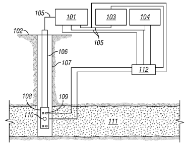
[000291 Figure 1 illustrates one embodiment of the
mechanical equipment that may be used. The pumping is performed using a fluid
pump 101 on surface 102. The treatment fluid and the fluid additive are stored
in their
own fluid tanks 103 and 104 and flow through the pump 101 at a rate and
proportion
controlled by the engineer. The mixture, formed by the treatment fluid and the
fluid
additive, then flows through surface lines 105 and then down into the wellbore
107
through a flow path 106, typically production tubing, the casing, a drill
pipe, or coiled
tubing. At the end of the flOw path 106, the fluid enters the bottom hole
assembly 108.
The bottom hole assembly 108 has multiple orifices 109 that may be closed or
open
remotely by the engineer. When flowing though an orifice, as represented in
Figure 3,
the fluid undergoes a pressure drop. The extent of the
pressure drop is controlled by the following.
= The pump rate
= The number of orifices open to flow
= The amount of fluid additive
CA 02822756 2013-06-21
WO 2012/087892
PCT/US2011/065760
7
[00030] The pressure drop causes the fluid to undergo a change in down hole
injection temperature as it leaves the bottom hole assembly 108 and flows into
the
reservoir 111. This change in down hole injection temperature may be monitored
at
the surface by using the temperature reading from temperature sensors 110
through
wireline communication or fiber optic cable. Alternatively, the down hole
injection
temperature may be obtained by other down hole temperature sensors (not shown)
such as a distributed temperature sensors or be predicted by a mathematical
model. In
any event, controller 112 may receive a signal from or send a signal to the
bottom
hole assembly, temperature sensor, pump, additive or fluid tanks, or lines
connecting
the tanks, pump, flow path, or assembly. Finally, the engineer may change some
of
the above three parameters to optimize the down hole injection temperature.
[00031] Figure 2 is a schematic diagram of details of a bottom hole assembly
108 in a
wellbore 107. The fluid flows through the flow path 106 to the assembly 108
with a
pressure drop illustrated by flow lines 201. Figure 2 shows flow lines 201 are
present
on open valves 202, but not on closed valves 203. Temperature sensors may also
be
placed across the surface of or embedded in or suspended near the assembly
108.
[00032] In the case where the down hole injection temperature must be
controlled for
the accuracy of the down hole temperature-based interpretation of the
treatment
performance, it is also possible to pump another fluid than the treatment
fluid, on its
own, in order to achieve the required down hole injection temperature. For
instance, if
it is estimated that, under the conditions under consideration, the down hole
injection
temperature may not be controlled by pumping the treatment fluid, another
fluid may
be pumped at some stages in order to achieve the required down hole injection
temperature for some time and to allow more accurate interpretation. For
instance, at
the end of an acid treatment, a gas may be pumped after the acids to achieve a
larger
change on the down hole injection temperature. This larger change on the down
hole
injection temperature will allow a more accurate interpretation concerning the
event
associated with the gas injection, which may be a direct consequence of the
treatment
performance. For instance, after having pumped the acid, the inflow profile
along the
well is what determines the acid treatment performance. Pumping a gas after
the acid,
with an optimum down hole injection temperature will reveal the inflow profile
during gas injection. The inflow profile during gas injection being a
consequence of
the performance of the acid, the acid performance may be estimated. After
pumping
CA 02822756 2013-06-21
WO 2012/087892 PCT/US2011/065760
8
the gas, the pump rate is set to zero and the well is shut-in while a
distributed
temperature sensor is logged. Looking at how fast the down hole temperature at
a
given depth warms back to the temperature before the treatment reveals how
much
was injected. Alternatively, the position of a gas slug, with a lower down
hole
injection temperature along the well may be monitored by distributed
temperature
sensors revealing which zones are accepting fluid during the pumping. The use
of
temperature logging such as distributed temperature sensors or a down hole
temperature on a moving tool as a means to identify injectiyity profiles based
on a
down hole injection temperature significantly different from the reservoir
temperature
is important to some embodiments.
[00033] The following thermodynamic calculations may be performed to determine
the down hole injection temperature as a function of the above three
parameters.
These calculations validate the concept of the use of the JT effect and may be
used as
a means of predicting the down hole injection temperature change with the
pressure
drop. The value of the pressure drop that the fluid will undergo when flowing
through
the orifices can be determined using Equation (1) and Equation (2):
1
PD p 4 )p,(112 (1)
2c2
7, PR PR
p ¨ ¨ , v 2 (2)
do Ad .n07-1- do
= PD is the Pressure Drop (Pa)
= V is the fluid flow velocity (m/s)
= c is the dimensionless discharge coefficient
= di, Is the upstream diameter (m)
= do is the orifice diameter (m)
= pF is the fluid density (kg/m3)
= Ad is the surface flow area formed by all no open orifices (m2)
= no is the number of orifices open to flow
CA 02822756 2013-06-21
WO 2012/087892 PCT/US2011/065760
9
[00034] If the fluid additive is a gas, the two fluids will undergo a
different pressure
drop, PDF for the treatment fluid and PDG for the gas, as described by
Equation (3)
1
and Equation PDG = i.1¨)64)PG(17q)2 (4).
2 c
1 i \\
PD =-1¨ PlpF(V(1¨ q))2 (3)
F 2 C2
PDG=1 (-1¨ )64 )pG(Vq)2 (4)
2 c2
= q is the volume fraction of gas in the mixture formed by the fluid and
the gas
= PG is the gas density (kg/m3)
[00035] In the general case where the FA is a gas, both fluids phases will
undergo a
change in down hole injection temperature, denoted DTF for the treatment fluid
and
DTG for the gas additive, as given by Equation (5) and Equation (6).
BHP
DTF = f tiF(p ,T F)dp (5)
BHP+DP,
BHP
DTG = f 77G(p,TG)dp (6)
BHP+DPG
= DT G is the temperature variation in the gas phase (K)
= DTF is the temperature variation in the fluid phase (K)
= riG is the gas Joule-Thomson coefficient (K/Pa)
= riF is the treatment fluid Joule-Thomson coefficient (K/Pa)
= BHP is the DH pressure in the wellbore (Pa)
= TG is the temperature in the gas phase (K)
= TF is the temperature in the fluid phase (K)
= p is the pressure (Pa)
[00036] The final value of the down hole injection temperature of the mixture
formed
by the treatment fluid and the gas can be determined using Equation (7).
CA 02822756 2013-06-21
WO 2012/087892 PCT/US2011/065760
qpGC pG DT G)+ (1¨ q)pFC pF (7' DT F)
DHIT =T + DTGF = T1 + ___________________________________________________ (7)
qpGCpG+(1¨q)pFCpF
= DHIT is the DH Injection Temperature (K)
= DTGF is the temperature variation of the mixture during the JT effect (K)
= CpG is the heat capacity of the gas (J/(kg K))
= CpF is the heat capacity of the fluid (J/(kg K))
= T1 is the initial temperature of the mixture in the BHA, before flowing
through
the orifices (K)
[00037] The physical and thermodynamic properties of the treatment fluid and
the
gas, pF,, PG, CpG, CpF, CpG, 11F,, 11G, are functions of the temperature and
pressure. It is
possible to determine those properties from an equation of state. An equation
of state
links the value of the fluid density, fluid temperature and pressure together.
The
determination of an equation of state for a given fluid or gas has been the
subject of a
vast amount of literature. For instance, an equation of state such as the one
from R.
Span and W. Wagner, "A New Equation of State for carbon Dioxide Covering the
Fluid Region from the Triple-Point to 1100K at Pressures up to 800 MPa", J.
Phys.
Chem. Ref Data, 25(6), 1996 may be used for carbon dioxide.
[00038] It is also possible to determine physical and thermodynamic properties
of the
treatment fluid and the gas, pF,, PG, CpG, CpF CpG riG from experiments.
Some of
such experiments demonstrate the ability of certain fluids to undergo a
temperature
change during a JT effect. It is understood that during expansion, a fluid may
experience heating, for a negative JT coefficient, or cooling for a positive
one, and the
scientific and technical literature provides numerous examples of the
experimental
values of the JT coefficient for numerous fluids. For instance, in J.R.
Roebuck, H.
Osterberg, "The Joule-Thomson Effect in Nitrogen", Physical Review, 48, 1935,
and
J.R. Roebuck et al, "The Joule-Thomson Effect in Carbon Dioxide", J. Am. Chem.
Soc., 64, 1947, the values of the JT coefficient have been measured
experimentally
for nitrogen, and carbon dioxide, under various conditions in temperature and
pressure, and the experimental data reported in these references,
respectively, show
that the JT coefficient may be positive or negative, highlighting zones of
cooling and
zones of heating respectively for these fluids.
CA 02822756 2013-06-21
WO 2012/087892 PCT/US2011/065760
11
[00039] The method is now illustrated in the case where the treatment fluid is
an
aqueous acid and the fluid additive is carbon dioxide (CO2). Considering a 15
weight
percent hydrochloric acid (15% HC1) solution being pumped with CO2 with a down
hole foam quality q equal to 0.5, the down hole injection temperature may be
determined using Equations (1) to (7) and by using an equation of state for
CO2 as
follows. First, and for the purpose of this example, the treatment fluid, 15 %
HC1,
being a liquid, the variations of pF,, CF, and riF, during the flow through
the orifices
are negligible. The following values are reasonable approximations:
pF = 1070 kg/m3, CPF = 4200 J/(kg F), 77, = -1 =
2.23x10⁻⁷ K/Pa (8)
P FC pF
[00040] For CO2, the determination of DTG requires computing Equation
BHP
DTG = 77G(p,TG)dp (6) along the expansion path experienced by the gas.
BHP+DPG
This may be done using numerical approximations as described by Equations (9)
to
(13) as, typically, the equation of state is a too complex formula to allow
the
integration in Equation (6) to be done by hand.
DTG = lim E PN (9)
N->00 C G(pi,TG,) aT
_ _ P
V G(pf,TGi) = 1
P G(1) ITG,)
PD
8PNN (11)
Pi= Pi_i gPN (12)
T av
T TGf_l + OPN , T )-
v (p TGf_l ) (13)
T GG1 G
pG i-11 Gi-1 \
[00041] Equations (9) to (13) can be solved using a large value for N. This
large value
N may be determined by solving Equations (9) to (13) with increasing values of
N
until the result does not change significantly when N becomes larger. To solve
Equations (9) to (13), it is possible to specify the final value of the
pressure during the
expansion, bottom hole pressure and the initial temperature in the bottom hole
assembly before the expansion, TF
CA 02822756 2014-12-30 =
51659-13
12
=
Tot =T1
p, = BHP
[00042] Equations (9) ¨ (15) solve the temperature evolution in the gas as it
expands
by expanding the gas by very small expansion steps and adding the effect of
all the
smaller steps until the final pressure drop is reached. To be able to do so,
the
determination of the specific volume Iv must be detailed. This requires the
use of an
equation of state for CO2. Typically, an equation of state provides an
explicit
expression of the pressure, given a value of the temperature and specific
volume Iv:
p = EOS(vo,TG)
[00043] However, determining vo from the values of p and To requires solving a
non-
linear equation. This may be done easily by using conventional optimization
algorithms such as the Newton method or the dichotomy method.
[00044] The problem consisting of solving Equations (9) ¨ (16) has been solved
using
the equation of state from R. Span and W. Wagner 141. Figure 8
illustrate the values of DTG as a function of the final pressure alter
expansion
(BHP) and the initial temperature before expansion T1. In Figure 5,
the value of 77y is plotted for various values of pressure and temperature.
The fact that 2/G is positive over a wide range of pressure and temperature
shows that
=
CO2 cools down under the JT effect. Solving Equations (9) to (16), the changes
of
temperature in the gas (DTG) and in the mixture (DTGF) are plotted in
Figure 6 and Figure 7, respectively,
for a value of pressure drop of -1000 PSI. Increasing the pressure drop to -
2000 PSI,
the fluids cool down further as plotted in Figure 8 and
Figure 9, but the area affected by the cooling does not
vary significantly. It can also be seen that the cooling of the gas is larger
than the
cooling of the mixture. Depending on the situation, gas alone may therefore be
pumped for maximum cooling. It may also be seen that the pressure drop must be
large enough for significant cooling to occur, When pressure drop = -100 PSI,
the
temperature change is much smaller (Figure 10)
CA 02822756 2014-12-30
51659-13
=
13
and therefore, if the engineer aims at cooling
down by 5K, the pump rate and the controlled flow device must be controlled in
such
a way the pressure drop is closer to -1000 PSI.
=
Examples.
[00045] The following examples are presented to illustrate the preparation and
properties of fluid systems, and should not be construed to limit the scope of
the
application, unless otherwise expressly indicated in the appended claims. All
percentages, concentrations, ratios, parts, etc. are by weight unless
otherwise noted or
apparent from the context of their use.
[00046] Figure 4 plots the value of the JT coefficient riG for CO2 as a
function of
pressure and temperature.
[00047] Figure 5 plots the DTG for CO2 for various initial temperature Ti and
pressure after TT effect (BHP) with a PD equal to -1000 PSI. Data truncated
between -
5K and +5K.
[00048] Figure 6 is a plot of DTGF for CO2 for various initial temperature Ti
and
pressure after JT effect (BHP) with a PD equal to -1000 PSI. Data truncated
between -
5K and +5K. Figure 7 is a plot of DTG for CO2 for various initial temperature
T1 and
pressure after IT effect (BHP) with a PD equal to -2000 PSI. Figure 8 is a
plot of Data
truncated between -5K and +5K. Figure 8 plots DTGF for CO2 for various initial
temperature T1 and pressure after IT effect (BHP) with a PD equal to -2000
PSI. Data
truncated between -5K and +5K. Figure 9 is a plot of DTG for CO2 for various
initial
temperature T1 and pressure after TT effect (BHP) with a PD equal to -100 PSI.
Data
truncated between -5K and +5K. Figure 10 is a plot of DTGF for CO2 for various
initial temperature T1 and pressure after JT effect (BHP) with a PD equal to --
100 PSI.
Data truncated between -5K and +5K
[00049] The particular embodiments disclosed above are illustrative only, as
the
application may be modified and practiced in different but equivalent manners
apparent to those skilled in the art having the benefit of the teachings
herein.
Furthermore, no limitations are intended to the details herein shown, other
than as
described in the claims below. It is therefore evident that the particular
embodiments
disclosed above may be altered or modified and all such variations are
considered
CA 02822756 2014-12-30
51659-13
14
within the scope of the application. Accordingly, the protection sought
herein is as set forth in the claims below.