Note: Descriptions are shown in the official language in which they were submitted.
I
CA 02822824 2013-08-02
LOUDNESS BASED METHOD AND SYSTEM FOR DETERMINING
RELATIVE LOCATION OF AN ACOUSTIC EVENT ALONG A CHANNEL
TECHNICAL FIELD
100011
The present disclosure is directed at methods, systems, and techniques for
determining relative location of an acoustic event along a channel. More
particularly, the
present disclosure is directed at methods, systems, and techniques that
determine the
relative location of the acoustic event using the relative loudnesses of two
or more
acoustic signals generated by measuring the acoustic event at different and
known
locations along the channel.
BACKGROUND
100021
During oil and gas drilling, a wellbore is drilled into a formation and then
one or more strings of tubing or casing are inserted into the wellbore. For
example,
surface casing may line an upper portion of the wellbore and protrude out the
top of the
wellbore; one or both of production tubing and casing may be inserted into the
wellbore
to facilitate production; and intermediate casing, which is located between
the production
and surface casings, may also be present in the wellbore.
[0003]
Gas migration and casing vent flow are both typical problems encountered
during oil and gas drilling. For example, gas migration and casing vent flow
can refer to
any one or more of the following phenomena:
= fluid
flowing from the formation into an outermost annular portion of the
wellbore behind an outermost casing string in the wellbore;
= fluid flowing from the outermost annular portion of the wellbore into the
formation; and
= fluid flowing across any of the casing or tubing strings in the wellbore.
- 1 -
I
CA 02822824 2013-08-02
,
,
In gas migration and casing vent flow, the moving fluid may be liquid or
gaseous, and
may eventually leak out of the wellbore and into the atmosphere, which harms
the
environment. Accordingly, when evidence of gas migration or casing vent flow
is found,
the location at which the fluid is flowing into the wellbore, the formation,
or across the
casing or tubing string is identified and a repair is performed. Such a
process can be time
intensive, costly, and inefficient.
[0004] Accordingly, research and development continue into
methods, systems,
and techniques that can be used to more robustly and efficiently identify and
repair
occurrences of gas migration and casing vent flow.
SUMMARY
[0005] According to a first aspect, there is provided a
method for determining
relative location of an acoustic event along a channel. The method comprises
obtaining
two acoustic signals at two different and known locations along the channel,
wherein at
least one of the acoustic signals includes the acoustic event; dividing each
of the acoustic
signals into windows, each of which has a certain duration; determining
relative
loudnesses of pairs of the windows, wherein each of the pairs comprises one
window
from one of the acoustic signals and another window from the other of the
acoustic
signals that substantially overlap each other in time; and determining the
relative location
of the acoustic event relative to the two known locations from the relative
loudnesses.
[0006] The channel may comprise a wellbore; the relative location may be
relative depth; and the acoustic event may comprise fluid flowing from
formation into the
wellbore, fluid flowing from the wellbore into the formation, or fluid flowing
across any
casing or tubing located within the wellbore. Alternatively, the acoustic
event may
comprise a leak along a pipeline (in which case the channel is the pipeline)
or sounds
observed in an observation well from a nearby well in which fracking is being
performed
(in which case the channel is the observation well).
- 2 -
CA 02822824 2013-08-02
[0007] The acoustic event may be fluid flowing from formation into
the wellbore,
fluid flowing from the wellbore into the formation, or fluid flowing across
any casing or
tubing located within the wellbore.
[0008] Both of the acoustic signals may comprise the acoustic event.
the acoustic event at the two different and known depths.
[0010] The windows that comprise any one of the pairs of the windows
may
represent concurrent portions of the acoustic signals.
[0011] The windows that comprise any one of the pairs of the windows
may be
time staggered such that the acoustic event is represented in both the windows
of the pair.
[0012] The windows into which any one of the acoustic signals is
divided do not
have to overlap with each other.
[0013] Determining the relative loudnesses of each of the pairs of
the windows
may comprise determining relative powers of each of the pairs of windows by
performing
a method including, for each of the windows of the pair, determining the RMS
amplitude
of the portion of the acoustic signal within the window; and determining a
loudness ratio
comprising the ratio of the square of the RMS amplitude of a first of the
windows of the
pair relative to the sum of the squares of the RMS amplitudes of both of the
windows of
the pair.
may comprise determining relative magnitudes of each of the pairs of windows
according
to a method comprising for each of the windows of the pair, determining the
RMS
amplitude of the portion of the acoustic signal within the window; and
determining a
loudness ratio comprising the ratio of the RMS amplitude of a first of the
windows of the
pair relative to the total RMS amplitudes of both of the windows of the pair.
- 3 -
CA 02822824 2013-08-02
[0015] Determining the relative depth of the acoustic event may
comprise
obtaining an indication of the relative depth of the acoustic event from the
loudness ratio;
and determining whether the acoustic event is above the shallower of the two
known
depths or below the deeper of the two known depths by comparing each of the
loudness
ratios of the pairs of the windows to a ratio threshold, wherein one of the
pairs indicates
the acoustic event is above the shallower of the two known depths when the
loudness
ratio indicates that the acoustic event is louder at the shallower of the two
known depths
than the deeper of the two known depths, and one of the pairs indicates the
acoustic event
is below the deeper of the two known depths when the loudness ratio indicates
that the
acoustic event is louder at the deeper of the two known depths than the
shallower of the
two known depths.
[0016] Determining whether the acoustic event is above the shallower
of the two
known depths or below the deeper of the two known depths may comprise
determining
how many of the pairs indicates that the acoustic event is above the shallower
one of the
two known depths or below the deeper one of the two known depths; and
determining
whether the acoustic event is above the shallower one of the two known depths
or below
the deeper one of the two known depths from how many of the pairs indicate
that the
acoustic event is above the shallower one of the two known depths or below the
deeper
one of the two known depths.
[0017] The acoustic event may be determined to be above the shallower one
of
the two known depths when at least half of the pairs indicate that the
acoustic event is
above the shallower one of the two known depths, and otherwise may be
determined to
be below the deeper of the two known depths.
[0018] It may also be determined that the acoustic event is above a
deemed
reference depth when the acoustic event is determined to be above the
shallower one of
the two known depths, and that the acoustic event is below the deemed
reference depth
when the acoustic event is determined to be below the shallower of the two
known
depths. The deemed reference depth is midway between the two known depths.
- 4 -
I
CA 02822824 2013-08-02
[0019] The method may also comprise determining a measured time
difference of
the acoustic event as recorded in the acoustic signals; comparing the measured
time
difference to a minimum time difference; only using the loudness ratio to
determine the
relative depth of the acoustic event if the measured time difference equals or
exceeds the
minimum time difference; obtaining new acoustic signals corresponding to new
known
depths if the measured time difference is less than the minimum time
difference, wherein
the measured time difference of the acoustic event as recorded in the new
acoustic signals
equals or exceeds the minimum time difference; and determining the relative
depth of the
acoustic event using the new acoustic signals.
[0020] Obtaining the acoustic signals may comprise measuring the acoustic
event
at the two different and known depths using a fiber optic sensor assembly
comprising a
fiber optic cable having two pressure sensing regions spaced from each other,
and each of
the pressure sensing regions may have top and bottom ends and the minimum time
difference may be the time for sound to travel between the top end of the
deeper one of
the pressure sensing regions to the bottom end of the shallower one of the
pressure
sensing regions.
[0021] The method may also comprise determining a measured time
difference of
the acoustic event as recorded in the acoustic signals; comparing the time
difference to a
maximum time difference; only using the magnitude ratio to determine the
relative depth
of the acoustic event if the time difference is less than or equals the
maximum time
difference; obtaining new acoustic signals corresponding to new known depths
if the
measured time difference exceeds the minimum time difference, wherein the
measured
time difference of the acoustic event as recorded in the new acoustic signals
is less than
or equal to the maximum time difference; and determining the relative depth of
the
acoustic event using the new acoustic signals.
[0022] Obtaining the acoustic signals may comprise measuring the
acoustic event
at the two different and known depths using a fiber optic sensor assembly
comprising a
fiber optic cable having two pressure sensing regions spaced from each other,
and each of
-5..
CA 02822824 2013-08-02
the pressure sensing regions may have top and bottom ends and the maximum time
difference may be the time for sound to travel between the bottom end of the
deeper one
of the pressure sensing regions to the top end of the shallower one of the
pressure sensing
regions.
[0023] The method may also comprise graphing, using at least two types of
indicators, on a plot comprising depth whether the acoustic event is above the
shallower
of the two known depths or below the deeper of the two known depths at various
depths
over which the acoustic event is measured.
[0024] The indicators may comprise two different colors.
[0025] The plot may further comprise time plotted versus the depth, wherein
the
plot shows whether the acoustic event is above the shallower of the two known
depths or
below the deeper of the two known depths at various depths and times over
which the
acoustic event is measured.
[0026] The acoustic event may have a frequency of between about 10
kHz to 250
kHz, and more particularly between about 2 kHz and 20 kHz.
[0027] The two different and known depths may be less than about 5 m
apart.
[0028] The method may also comprise obtaining a third acoustic signal
at a third
different and known depth in the wellbore, wherein the third acoustic signal
includes the
acoustic event; and determining the relative depth of the acoustic event
relative to one or
both of (i) one of the two different and known depths and the third different
and known
depth and (ii) the other of the two different and known depths and the third
different and
known depth.
[0029] The relative depth of the acoustic event may be determined
relative to the
two different and known depths when the acoustic event is less than about 2
kHz, and the
relative depth of the acoustic event may be determined relative to the third
different and
- 6 -
CA 02822824 2013-08-02
known depth and one of the other different known depths when the acoustic
event is
greater than about 2 kHz.
100301 According to another aspect, there is provided a system for
determining
relative location of an acoustic event along a channel. The system comprises a
sensor
assembly comprising a cable having two sensors spaced from each other, wherein
the
sensor assembly is configured to measure the acoustic event using the two
sensors and to
correspondingly output two analog acoustic signals; a spooling mechanism on
which the
cable is wound and that is configured to lower and raise the cable into and
out of the
channel; a data acquisition box communicatively coupled to the sensor assembly
and
configured to digitize the acoustic signals; and a processor communicatively
coupled to
(i) the data acquisition box to receive the acoustic signals that have been
digitized and a
computer readable medium having encoded thereon statements and instructions to
cause
the processor to perform any of the aspects of the method described above or
combinations thereof
100311 The cable may comprise a fiber optic cable and the sensors may
comprise
two pressure sensing regions.
100321 According to another aspect, there is provided a non-
transitory computer
readable medium having encoded thereon statements and instructions to cause a
processor to perform any aspects of the method described above or combinations
thereof.
[0033] This summary does not necessarily describe the entire scope of all
aspects.
Other aspects, features and advantages will be apparent to those of ordinary
skill in the
art upon review of the following description of specific embodiments.
BRIEF DESCRIPTION OF THE DRAWINGS
100341 In the accompanying drawings, which illustrate one or more
exemplary
embodiments:
- 7 -
I
CA 02822824 2013-08-02
[0035] FIG. 1 shows a schematic of a system for determining relative
location of
an acoustic event along a channel in which the channel is a wellbore and
location along
the channel corresponds to depth, according to one embodiment.
[0036] FIGS. 2A and 2B show waveforms of acoustic signals recorded
using top
and bottom sensors comprising part of the system of FIG. 1 and positioned at
two
different and known depths within the wellbore.
[0037] FIGS. 2C and 2D show the RMS magnitudes of the acoustic
signals of
FIGS. 2A and 2B, respectively.
[0038] FIG. 3 shows two sensors in the form of pressure sensing
regions that
form part of a fiber optic sensor assembly used in the system of FIG. 1.
[0039] FIG. 4 shows a method for determining the relative depth of
the acoustic
event within the wellbore, according to another embodiment.
[0040] FIG. 5 shows an embodiment of a method for determining
relative power
of the acoustic signals and for determining the relative depth of the acoustic
event from
the relative power of the acoustic signals, which can comprise part of the
method of FIG.
4.
[0041] FIG. 6 depicts another pair of acoustic signals acquired using
the system
of FIG. 1, in which a relatively high level of noise is present for
approximately half the
signals' duration.
100421 FIG. 7 shows plots indicating whether the acoustic event is
shallower or
deeper than a deemed reference depth of the system of FIG. 1 at various deemed
reference depths.
[0043] FIGS. 8A and 8B show two additional embodiments of the fiber
optic
sensor assembly that can be used in the system of FIG. 1.
- 8 -
CA 02822824 2013-08-02
[0044] FIG. 9 shows graphs of power spectral density vs. frequency
for another
pair of acoustic signals acquired using the system of FIG. 1.
DETAILED DESCRIPTION
[0045] Directional terms such as "top," "bottom," "upwards,"
"downwards,"
"vertically," and "laterally" are used in this description for the purpose of
providing
relative reference only, and are not intended to suggest any limitations on
how any article
is to be positioned during use, or to be mounted in an assembly or relative to
an
environment. Additionally, the term "couple" and variants of it such as
"coupled,"
"couples," and "coupling" as used in this description are intended to include
indirect and
direct connections. For example, if a first device is coupled to a second
device, that
coupling may be through a direct connection or through an indirect connection
via other
devices and connections. Similarly, if the first device is communicatively
coupled to the
second device, communication may be through a direct connection or through an
indirect
connection via other devices and connections.
[0046] Casing vent flow ("CVF") and gas migration ("GM") are problems that
are becoming increasingly significant in the oil and gas industry. CVF and GM
may
occur at any time during the life of a wellbore: while the wellbore is being
drilled (pre-
production); while the wellbore is being used to produce oil or gas; and while
the
wellbore is abandoned. The fluid migration that occurs within the wellbore
during CVF
and GM typically commences with fluid, such as a gaseous or liquid
hydrocarbon,
entering the wellbore from the formation into which the wellbore was drilled,
entering the
formation from the wellbore, or crossing any of the tubing or casing strings
within the
wellbore. When the fluid enters the wellbore from the formation or crosses the
tubing or
casing string (hereinafter collectively referred to as "leaks"), it makes a
noise (hereinafter
referred to as an "acoustic event"). This acoustic event can be detected using
well
logging.
- 9 -
CA 02822824 2013-08-02
[0047] The wellbore in which the CVF or GF occurs is one example of a
channel
along which acoustic events may occur and be monitored. Other examples of
channels
include a pipeline and an observation well drilled near to a well in which
hydraulic
fracturing ("fracking") is being performed. For the channel, acoustic events
include
events caused by leaks in the pipeline. For the observation well, acoustic
events include
sounds caused by creation or expansion of fractures in the frocking well.
[0048] The embodiments described herein are directed at a method and
system
for determining relative location of an acoustic event along a channel. One
example used
to describe this method and system is the example in which the channel is a
wellbore, the
acoustic event is caused by CVF or GM, and the method and system are used to
determine the relative depth of the acoustic event in the wellbore. Once the
source of the
CVF or GM is located, repairs can be performed to end the CVF or GM. For
example, if
the CVF or GM is being caused by a crack in a tubing or casing string, this
crack can be
plugged. In the example in which the acoustic event is caused by CVF or GM,
the depth
of the acoustic event is determined relative to two different depths at which
the acoustic
event is measured from the difference in loudnesses of the acoustic event at
those two
different depths. The power of portions of the signals generated at those two
different
depths is used as a proxy for the loudness of the acoustic event. The signals
generated at
the two different depths are divided into windows, and the power of the
portions of the
signals within the windows are compared to each other to determine the
relative depth of
the acoustic event.
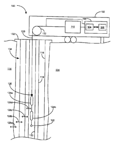
[0049] Referring now to FIG. 1, there is shown a schematic of a
system 100 for
determining relative location of an acoustic event within a channel, according
to one
embodiment. In FIG. 1, the channel comprises a wellbore 134 and location along
the
channel corresponds to depth of the wellbore 134. The wellbore 134 is drilled
into a
formation 114 that contains oil or gas deposits (not shown). Various casing
and tubing
strings are then strung within the wellbore 134 to prepare it for production.
In FIG. 1,
surface casing 116 is the outermost string of casing and circumscribes the
portion of the
-10-
CA 02822824 2013-08-02
interior of the wellbore 134 shown in FIG. 1. A string of production casing
118 with a
smaller radius than the surface casing 116 is contained within the surface
casing 116, and
an annulus (unlabeled) is present between the production and surface casings
118,116. A
string of production tubing 120 is contained within the production casing 118
and has a
smaller radius than the production casing 118, resulting in another annulus
(unlabeled)
being present between the production tubing 120 and casing 118. The surface
and
production casings 116,118 and the production tubing 120 terminate at the top
of the
wellbore 134 in a wellhead 132 through which access to the interior of the
production
tubing 120 is possible.
[0050] Although the wellbore 134 in FIG. 1 shows only the production and
surface casings 118,116 and the production tubing 120, in alternative
embodiments (not
shown) the wellbore 134 may be lined with more, fewer, or alternative types of
tubing or
casing. For example, in one such alternative embodiment a string of
intermediate casing
may be present in the annulus between the surface and production casings
116,118. In
another such alternative embodiment in which the wellbore 134 is pre-
production, only
the surface casing 116, or only the surface and production casings 116,118,
may be
present.
[0051] FIG. 1 also shows four examples of leaks 128a-d (collectively,
"leaks
128") that generate acoustic events. One of the leaks 128a corresponds to
fluid crossing
the formation 114's surface, either into the wellbore 134 from the formation
114 or vice-
versa. Another of the leaks 128b corresponds to fluid crossing the surface
casing 116,
while a third leak 128c corresponds to fluid crossing the production casing
118, and a
fourth leak 128d corresponds to fluid crossing the production tubing 120. As
mentioned
above, in alternative embodiments (not shown) the wellbore 134 may contain
more,
fewer, or other types of casing or tubing strings, and in such embodiments the
leaks may
result from fluid crossing any or more of these strings.
[0052] Lowered through the wellhead 132 and into the wellbore 134,
through the
production tubing 120, is a fiber optic sensor assembly. The fiber optic
sensor assembly
-11-
CA 02822824 2013-08-02
includes a fiber optic cable 130 that is optically coupled, via an optical
connector 126, to
a pair of pressure sensing regions 124: a shallower pressure sensing region
124a that is
located at a shallower depth than a deeper pressure sensing region 124b; each
of the
pressure sensing regions 124a,b is hereinafter referred to as a "sensor"
124a,b, and the
pressure sensing regions 124 collectively are referred to as the "sensors"
124. Each of
the sensors 124 is located along its own fiber optic strand and is sensitive
to strains that
result from detection of the acoustic event. The fiber optic assembly also
includes a
weight 122 coupled below the lower sensor 124b to help ensure the fiber optic
cable 130
is relatively taut during well logging. An exemplary fiber optic sensor
assembly is
described, for example, in PCT patent application having serial number
PCT/CA2008/000314, publication number W0/2008/098380, and entitled "Method and
Apparatus for Fluid Migration Profiling". In an alternative embodiment (not
depicted), a
single fiber strand that has multiple sensors on it may be used, with the
signals from the
multiple sensors being multiplexed back to the surface. In other alternative
embodiments
different types of sensor assemblies may be used. For example, non-fiber based
assemblies, such as electrical assemblies and piezoelectric sensors, may be
used.
[0053] The fiber optic strands themselves may be made from quartz
glass
(amorphous Si02). The fiber optic strands may be doped with a rare earth
compound,
such as germanium, praseodymium, or erbium oxides) to alter their refractive
indices.
Single mode and multimode optical strands of fiber are commercially available
from, for
example, Corning Optical Fiber. Exemplary optical fibers include ClearCurveTM
fibers
(bend insensitive), SMF28 series single mode fibers such as SMF-28 ULL fibers
or SMF-
28e fibers, and InfiniCor series multimode fibers.
[0054] When the sensors 124 detect the acoustic event, they generate
acoustic
signals 200a,b (collectively, "acoustic signals 200", which are not shown in
FIG. 1 but
are shown in FIGS. 2A and 2B and FIG. 6) that are transmitted to the surface.
The
shallower, or "top", sensor 124a generates one of the acoustic signals 200a
and the
deeper, or "bottom", sensor 124b generates the other of the acoustic signals
200b. The
- 12 -
CA 02822824 2013-08-02
acoustic signals 200 generated by the sensors are transmitted along the fiber
optic cable
130, past a spooling device 112 around which the fiber optic cable 130 is
wrapped and
that is used to lower and raise the cable 130 into and out of the wellbore
134, and to a
data acquisition box 110. The data acquisition box 110 digitizes the acoustic
signals 200
and sends them to a signal processing device 108 for further analysis. The
digital
acquisition box 110 may be, for example, an OptiphaseTM TDI7000.
[0055] The signal processing device 108 is communicatively coupled to
both the
data acquisition box 110 to receive the digitized acoustic signals and to the
spooling
device 112 to be able to determine the depths at which the acoustic signals
200 were
generated (i.e. the depths at which the sensors 124 were when they measured
the acoustic
event), which the spooling device 112 automatically records. The signal
processing
device 108 includes a processor 104 and a non-transitory computer readable
medium 106
that are communicatively coupled to each other. The computer readable medium
106
includes statements and instructions to cause the processor 104 to perform any
one or
more of the exemplary methods depicted in FIGS. 4 and 5, below, which are used
to
determine the relative depth of the acoustic event. The spooling device 112,
data
acquisition box 110, and signal processing device 108 are all contained within
a trailer
102 to facilitate transportation to and from the wellbore 134.
[0056] Referring now to FIG. 4, there is shown a method 400 for
determining the
relative depth of the acoustic event within the wellbore, according to another
embodiment. The method 400 may be encoded on to the computer readable medium
106
to cause the processor 104 to perform the method 400 on the acoustic signals
200 that the
signal processing device 108 receives from the data acquisition box 110. At
block 402,
the processor 104 begins performing the method 400. At block 404, the
processor 104
acquires the acoustic signals 200 from the data acquisition box 110. As
mentioned
above, because each of the acoustic signals 200 is generated using one of the
sensors 124,
the depths of which are known from the spooling device 112, the processor 104
knows
the depths at which each of the acoustic signals 200 was measured.
- 13
I
CA 02822824 2013-08-02
100571 Although not shown in FIG. 4, the processor 104 filters the
acoustic
signals 200 prior to performing any further signal processing on them. In
order to
condition the signals 200 for further processing, in the depicted embodiment
the
processor 104 filters the acoustic signals 200 through a 10 Hz high pass
filter, and then in
parallel through a bandpass filter having a passband of between about 10 Hz to
about 200
Hz, a bandpass filter having a passband of about 200 Hz to about 600 Hz, a
bandpass
filter having a passband of about 600 Hz to about 1 kHz, a bandpass filter
having a
passband of about 1 kHz to about 5 kHz, a bandpass filter having a passband of
about 5
kHz to about 10 kHz, a bandpass filter having a passband of about 10 kHz to
about 15
kHz, and a high pass filter having a cutoff frequency of about 15 kHz. The
processor 104
can digitally implement the filters as, for example, 5th or 6th order
Butterworth filters. By
filtering the acoustic signals 200 in parallel in this manner, the processor
104 is able to
isolate different types of the acoustic events that correspond to the
passbands of the
filters. In an alternative embodiment (not shown), the filtering performed on
the acoustic
signals 200 may be analog, or a mixture of analog and digital, in nature, and
may be
partially or entirely performed outside of the signal processing device 108,
such as in the
data acquisition box 110. Alternative types of filters, such as Chebychev or
elliptic filters
with more or fewer poles than those of the Butterworth filters discussed above
may also
be used, for example in response to available processing power.
[0058] Examples of two acoustic signals 200 corresponding to one of these
passbands and generated simultaneously from measuring the same acoustic event
at
different depths are shown in FIGS. 2A and 2B. In FIGS. 2A and 2B the acoustic
event
emits a signal of 10 kHz. In this context, "simultaneously" refers to
measuring the
acoustic event from time = to to time = t' at both of the sensors 124, where
time is
measured at a reference point away from and stationary relative to the sensors
124. In
FIGS. 2A and 2B, the acoustic signal 200a shown in a solid line is generated
with the
shallower sensor 124a, while the acoustic signal 200b shown in a dashed line
is generated
with the deeper sensor 124b. In FIG. 2A the acoustic event is generated below
the deeper
sensor 124b and are therefore nearer to the deeper sensor 124b than the
shallower sensor
- 14 -
1
CA 02822824 2013-08-02
124a, and the acoustic signal 200b generated with the deeper sensor 124b
accordingly has
a larger average value than the signal 200a generated with the shallower
sensor 124a.
Conversely, in FIG. 2B, the acoustic event is generated above the shallower
sensor 124a,
and the acoustic signal 200a generated with the shallower sensor 124a
accordingly has a
larger average value than the signal 200b generated with the deeper sensor
124b.
[0059] At
block 406 the processor 104 divides each of the acoustic signals 200
into windows w,
wõ. To illustrate this, the signals 200 shown in FIGS. 2A and 2B are
divided into windows, and the first four windows w, wa for each of the signals
200 are
labeled. The outputs of each of the filters that filter the acoustic signals
200 in parallel
are divided into windows; in the above example in which four different filters
are used to
filter the acoustic signals 200 in parallel, four different pairs of the
acoustic signals 200
are windowed. For any given integer k E [1_4 wk for one of the acoustic
signals 200
and wk for the other of the acoustic signals 200 together constitute a pair of
the windows,
or a "window pair", W
k_pair= The duration chosen for each of the windows may range
from 0.001s to greater than is. In FIGS. 2A and 2B, the windows are each 0.001
s long.
In the depicted embodiment, because each of the windows in one of the acoustic
signals
200 has a counterpart in the other acoustic signal 200 with identical start
and end times,
any given window pair Wk_pair for the acoustic signals 200 represents
concurrent portions
of the signals 200. In an alternative embodiment, the windows of any given
window pair
wkipair do not have to be concurrent, but may, for example, be non-concurrent
but
substantially overlap each other such that their relative powers nonetheless
remain
indicative of whether the acoustic event is nearer to the shallower sensor
124a or the
deeper sensor 124b, as discussed in more detail below.
[0060] After dividing the acoustic signals into the windows w,
wn, the
processor 104 at block 408 determines the relative loudnesses of the portions
of the
acoustic signals 200 contained in each of the window pairs Wk_pair for k E
[1...n], and
from these relative loudnesses determines, at block 410, the depth of the
acoustic event
relative to the known depths of the sensors 124. Loudness of the acoustic
signals 200 can
- 15 -
CA 02822824 2013-08-02
be represented in several ways. Referring now to FIG. 5, there is shown one
embodiment
of a method by which the processor 104 may perform blocks 408 and 410 and in
which
the power of the acoustic signals 200 is used as a proxy for loudness.
[0061]
When performing the method of FIG. 5, the processor 104 begins at block
502 and determines whether any more window pairsw. 1,
_pair of the acoustic signals 200
remain to be analyzed. If yes, the processor 104 proceeds to block 504 to
begin the
analysis on one of the remaining window pairs w
At block 504 the processor
determines the RMS amplitude of each of the windows of the pair W
k_pair= FIGS. 2C and
2D show the RMS amplitudes of the acoustic signals 200 shown in FIGS. 2A and
2B,
respectively. For each of the windows wk, the processor 104 determines the RMS
amplitude over the duration of that window wk.
[0062]
Once the processor 104 has determined the RMS amplitude of each of the
windows of the window pair Wk_pair at block 504, the processor 104 proceeds to
block 506
where it determines a power ratio for the window pair w
The processor 104
determines the power ratio from the RMS amplitude of the shallower sensor 124a
(RMS shallow) and the RMS amplitude of the deeper sensor 124b (RMSdeep). For
the
shallower sensor 124a, the power ratio (PRshallow) iS
PRshallow = (RMS2shallow) (RMS2shallovv RMS2deeP).
(1)
[0063] For the deeper sensor 124b, the power ratio (PRdeep) is
PRdeep = (RMS2deep) / (RMS2shallow RMS2deep)- (2)
[0064] As
the depicted embodiment of the system includes only the two sensors
124, PRdeep also equals (1 ¨ PRshallow). In an alternative embodiment (not
depicted), other
metrics aside from power may be used as a proxy for loudness. For example,
magnitude
may be used instead of power, and instead of a power ratio the processor 104
may
determine a magnitude ratio in which MRshallow = RMSshallow / (RMSshallow +
RMSdeep),
and in which the processor 104 may analogously determine MRdeep. Both the
power and
-16-
CA 02822824 2013-08-02
magnitude ratios described above are exemplary types of loudness ratios, and
in
alternative embodiments other types of loudness ratios or variations on the
foregoing
power and magnitude ratios are possible. For example, in another alternative
embodiment (not depicted), the processor 104 may use a value other than RMS
amplitude
when determining power or magnitude ratios, such as peak or average non-RMS
amplitude, at block 504.
[0065] After determining the power ratios, the processor 104 proceeds
to block
508. At block 508 the processor 104 obtains an indication of the relative
depth of the
acoustic event by comparing the power ratios to a ratio threshold. If PRshanow
exceeds the
ratio threshold, the processor 104 determines that the window pair Wk_pair
from which
PRshallow was determined indicates that the acoustic event is louder at the
shallower sensor
124a than the deeper sensor 124b, which indicates the acoustic event is above
the
shallower sensor 124a. Analogously, if PRdeep exceeds the ratio threshold, the
processor
104 determines that the window pair Wk_pair from which PRdeep was determined
indicates
that the acoustic event is louder at the deeper sensor 124b than the shallower
sensor 124a,
which indicates the acoustic event is louder at and below the deeper sensor
124b. In the
depicted embodiment, the ratio threshold is set to approximately 0.75. In
alternative
embodiments (not depicted), the ratio threshold may be set anywhere from 0 to
1 or at
any value within that range, and PRshallow and PRdeep may be compared to
different ratio
thresholds.
100661 Setting the ratio threshold above 0.50 is beneficial in that
the higher the
ratio threshold, the more powerful the acoustic signal 200 from one of the
sensors 124 is
before the processor 104 concludes that the window pair wk_pair indicates the
relative
location of the acoustic event. For example, if the window pair Wk_pair has
captured only
white noise and at a given instant RMSshatiow and RMSdeep are approximately
equal to
each other, PRshallow PRdeep "z 0.5. By setting the ratio threshold
substantially above 0.5,
such as at 0.75, the processor 104 will exclude from consideration those
window pairs
Wk_pair that contain insufficient information to be considered useful.
- 17-
I
CA 02822824 2013-08-02
[0067] Once the processor 104 has finished analyzing all the window
pairs Wk_pair
for the acoustic signals according to blocks 502 to 508, the processor
proceeds from
block 502 to 510 and determines how many of the window pairs Wk_pan indicate
the
acoustic event is above the shallower sensor 124a (i.e.: PRshallow > the ratio
threshold) and
how many of the window pairs w
k_patr indicate the acoustic event is below the deeper
sensor 124b (i.e. PRdeep > the ratio threshold). In the depicted embodiment,
the processor
104 determines that the acoustic event is above the shallower sensor 124a if
(PRshallow
the ratio threshold) for more of the window pairs Wk_pair than (PRdeep > the
ratio
threshold), and analogously determines that the acoustic event is below the
deeper
sensors 124b if (PRdeep > the ratio threshold) for more of the window pairs
wki,dp- than
(PRshallow > the ratio threshold). In an alternative embodiment, the processor
104 may
determine the relative depth of the acoustic event differently. For example,
the processor
104 may determine the average values of PRdeep and PRshallow for all the
window pairs
Wk_pair, and determine the relative depth of the acoustic event as being above
the
shallower sensor 124a if PRshallow has the higher average value and below the
deeper
sensor 124b if PRdeep has the higher average value.
100681 FIG. 3 shows a detailed view of the bottom of the fiber optic
sensor
assembly. As the sensors 124 are distributed, the acoustic signals 200 may be
generated
as a result of the acoustic event being detected anywhere along the length of
the sensors
124. Consequently, the minimum time that passes between the acoustic event
being
detected in the two acoustic signals 200 corresponds to the time it takes for
sound to
travel from the bottom end of the shallower sensor 124a to the top end of the
deeper
sensor 124b. This distance is labelled "minimum distance" in FIG. 3, and the
time it
takes for sound waves generated by the acoustic event to travel the minimum
distance is
the (minimum distance) / (speed of sound in the wellbore 134). In an exemplary
embodiment, the minimum distance is 0.108 m, the wellbore 134 is filled with a
fluid that
is mainly water and in which sound travels 1484 m/s, and the minimum time lag
is
accordingly 0.0000728 s. Similarly, the time it takes for sound to travel from
the top end
of the shallower sensor 124a to the bottom end of the deeper sensor 124b is
the
- 18-
I
CA 02822824 2013-08-02
"maximum distance" and is labelled in FIG. 3. The time it takes for the
acoustic event to
travel the maximum distance is the (maximum distance) / (speed of sound in the
wellbore
134). In the exemplary embodiment, the maximum distance is 0.75 m, and the
maximum
time lag is accordingly 0.0005054 s.
100691 In the depicted embodiment, given the relatively small distance
between
the sensors 124 relative to the depth of the wellbore 134, the processor 104
does not
attempt to determine whether the time difference between when the acoustic
signals
arrive at the sensors 124 is between the minimum and maximum time lags.
Instead, the
processor 104 uses all acoustic signals when determining the relative depth of
the
acoustic event regardless of when they are generated. In so doing, the
processor 104
accepts a higher margin of error in exchange for implementing a simpler
algorithm.
[0070] In an alternative embodiment (not depicted), if the processor
104
determines that sound waves generated simultaneously by the same acoustic
event arrives
at the sensors 124 at times differing by less than the minimum time lag, the
processor 104
does not use the portion of the acoustic signals 200 corresponding to that
acoustic event.
In another alternative embodiment (not depicted), the processor 104 may use
those
signals 200 to determine whether the acoustic event is located, for example,
between the
sensors 124. Analogously, if the processor 104 determines that sound generated
simultaneously from the same acoustic event arrives at the sensors 124 at
times differing
by more than the minimum time lag, the processor 104 does not use the portion
of the
acoustic signals 200 corresponding to that acoustic event, as they may be
indicative of
one or both of the sensors 124 measuring an acoustic reflection or of some
type of
measurement artefact. Instead, the processor 104 either actuates the spooling
device 130
and moves to a new pair of depths to obtain new acoustic signals 200, or uses
portions of
the acoustic signals 200 in which the acoustic event as recorded by the two
sensors 124 is
separated by a time between the minimum and maximum time lags.
[0071] In FIG. 3, the minimum and maximum distances are determined
relative to
the tops and bottoms of the sensors 124. However, in alternative embodiments
(not
-19-
I
CA 02822824 2013-08-02
depicted), these distances may be determined relative to different points on
the sensors
124. For example, it may be assumed for convenience that any measurements
obtained
using the sensors 124 are obtained at their midpoints, thus making the maximum
and
minimum distances equal to each other. Alternatively, instead of distributed
sensing
regions, non-distributed point sensors may be used, which also results in the
minimum
and maximum distances being equal to each other.
[0072] If, because of the time it takes for sound to travel from one
of the sensors
124a to the other of the sensors 124b and because of the duration selected for
the
windows, window pairs Wk_pair do not contain corresponding portions of the
acoustic
event, the processor 104 may time stagger the acoustic signals 200 relative to
the
windows so that each of the windows in a window pair wk_pair contain
corresponding
portions of the acoustic event to compare to each other.
[0073] In the depicted embodiment, the processor 104 determines a
deemed
reference depth 302 and for simplicity expresses the depth of the acoustic
event relative
to the deemed reference depth. The deemed reference depth 302 in the depicted
embodiment is the midpoint between the sensors 124. If the processor 104
determines
that the acoustic event is above the shallower sensor 124a, then the processor
104 tells a
user of the system 100 that the acoustic event is above the deemed reference
depth 302.
Conversely, if the processor 104 determines that the acoustic event is below
the deeper
sensor 124b, then it tells the user that the acoustic event is below the
deemed reference
depth 302. Doing so allows information to be presented to the user in an
easier to user
format than if the processor 104 uses the depths of the shallower and deeper
sensors 124
as reference depths. While in the depicted embodiment the reference depth 302
is at the
midpoint of the sensors 124, in alternative embodiments (not depicted) the
reference
depth 302 may be located elsewhere, such as along one of the sensors 124,
above the
shallower sensor 124a, or below the deeper sensor 124b.
[0074] Referring now to FIG. 7, in one embodiment the processor 104
may graph,
using at least two types of indicators such as the Xs and Os shown on the
plots in FIG. 7,
-20 -
I
CA 02822824 2013-08-02
whether the acoustic event is above or below the reference depth 302 at
various reference
depths and over various times over which the acoustic event is measured. In
FIG. 7, plots
are shown in which the acoustic signals 200 are filtered using bandpass
filters of 2,000
Hz, 5,000 Hz, 10,000 Hz, 15,000 Hz, and 20,000 Hz prior to being analyzed by
the
processor 104, and according to five known reference depths 302 A ¨ E in the
wellbore
134. Xs are used to indicate when one of the window pairs Wk_pair indicates
that the
acoustic event is above the reference depth 302 (PR
shallow > the ratio threshold), while Os
are used to indicate when one of the window pairs Wk_pair indicates that the
acoustic event
is below the reference depth 302 (PRdeep > the ratio threshold). A blank in
the plots along
the horizontal axis indicates that either no measurement was taken at that
time or that
neither PRshanow nor PRdep exceeded their respective ratio thresholds.
100751 Examining, for example, the 10,000 Hz plot at depths A and B,
the
processor 104 determines that for each of the window pairs Wk_pair in which
either PRdeep
or PRshallow > the ratio threshold the window pair w
¨k_pair indicates that the acoustic event
is below the deeper sensor 124b. In accordance with the methods described
above, the
processor 104 accordingly determines that the acoustic event is below
reference depths
302 A and B. At depth C, the processor 104 analogously determines that for
each of the
window pairs Wk_pair in which either PRieep or PRshallow > the ratio
threshold, the window
pair Wk_pair indicates that the acoustic event is above the shallower sensor
124a. The
processor 104 accordingly determines that the acoustic event is above depth C.
Reviewing this plot accordingly allows the user of the system 100 to determine
that the
acoustic event is located between depths B and C. As the sensors 124 are
lowered deeper
into the wellbore 134, the processor 104 at depths D and E determines that
another
acoustic event, different from the one detected between depths B and C, is
below each of
these reference depths 302.
100761 Some acoustic events of relatively low frequencies may resist
attenuation
particularly well within the wellbore 134, and an alternative embodiment of
the fiber
optic assembly, such as that shown in FIG. 8, may be used accordingly. In FIG.
8, a
- 21 -
I
CA 02822824 2013-08-02
middle sensor 124c is positioned between the top and bottom sensors 124a,b,
and is used
to obtain a third acoustic signal (not depicted) at a third different and
known depth within
the wellbore 134. The relative depth of the acoustic event can then be
determined
relative to the middle sensor 124c and one or both of the shallower sensor
124a and the
deeper sensor 124b, which can be used in addition to the relative depth
determined
relative to the shallower and deeper sensors 124a,b. Because higher
frequencies attenuate
more quickly within the wellbore 134 than lower frequencies, the shallower and
deeper
sensors 124a,b can be used to measure acoustic events having lower frequencies
than
measured by the middle sensor 124c and one of the top and bottom sensor
124a,b. In one
embodiment, while the middle sensor 124c and one of the top and bottom sensors
124a,b
is used to determine the relative depth of the acoustic event according to the
one of the
methods described above, the top and bottom sensors 124a,b can be used to
determine the
relative depth of the acoustic event in accordance with either an identical
method or an
alternative method, such as one of those described in PCT patent application
having serial
number PCT/CA2011/000031, publication number WO/2011/091505, and entitled
"Method for Detecting and Locating Fluid Ingress in a Wellbore". The midpoints
of the
shallower and deeper sensors 124a,b may be, for example, approximately 5 m
apart,
while the midpoint of the middle sensor 124c may be located 2.5 m from each of
the
shallower and deeper sensors 124a,b.
[0077] Referring now to FIG. 8B, there is shown another embodiment of the
fiber
optic assembly in which there are two pairs of shallower and deeper sensors,
the first pair
124a,b and a second pair 124a',b', separated by a certain length of the fiber
optic cable
130. This embodiment of the fiber optic assembly may be used, for example, in
order to
survey the wellbore 134 twice as fast by surveying two halves of the wellbore
134
simultaneously as opposed to using only one pair of the sensors 124 to survey
the entire
wellbore 134.
[0078] Also beneficially, dividing the acoustic signals into the
windows w1 wn
helps to compensate for non-idealities encountered in the field. Such non-
idealities
- 22 -
I
CA 02822824 2013-08-02
include, for example, multiple acoustic events having sources located at
different depths
simultaneously making noise, acoustic events having frequencies that vary over
time,
acoustic reflections, and interference. If, in an ideal situation a first
acoustic signal would
have a larger RMS amplitude than a second acoustic signal, the non-idealities
can result
in variance of signal amplitudes and distort the processor 104's analysis.
Dividing the
acoustic signals into the windows w1 wn
helps to mitigate the detrimental effects of
such non-idealities better than if a single magnitude ratio were determined
using the
entirety of the acoustic signals. For example, FIG. 6 shows a pair of acoustic
signals 200
in which Channel 1, which corresponds to the acoustic signal measured using
the
shallower sensor 124a, has a larger RMS magnitude than Channel 2, which
corresponds
to the acoustic signal measured using the deeper sensor 124b, but in which
this is
obscured by noise for slightly under half the duration of the signals. With
windowing, if
the processor 104 is configured to determine that when, for example, at least
45% of the
window pairs wk_pair show that when the magnitude ratio for Channel 1 exceeds
the
magnitude threshold, the processor 104 is able to correctly determine the
relative location
from the Channel 1 and 2 signals notwithstanding the presence of noise, which
may have
prevented the processor 104 from arriving at this determination if only a
single
magnitude ratio were determined using the entirety of the noise-corrupted
signals. The
use of windowing allows the portions of the signals relatively unaffected by
noise to form
the basis of the processor 104's determination.
[0079]
The processor 104 performs the method of FIG. 5 to determine the power
ratio for the window pair W
k_pair in the time domain. In an alternative embodiment and as
depicted in FIG. 9, the processor 104 may also determine the power ratio for
the window
pair wk_pair in the frequency domain.
[0080] FIG. 9 shows two graphs of power spectral density ("PSD") in W/Hz
against frequency in Hz. A top graph 900 shows the PSD obtained by performing
a
discrete Fourier Transform, such as a Fast Fourier Transform, on one window wk
of the
acoustic signal 200a generated by the shallower sensor 124a while a bottom
graph 902
- 23 -
I
CA 02822824 2013-08-02
shows the PSD obtained by performing the discrete Fourier Transform on one
window wk
of the other acoustic signal 200b, which is generated by the deeper sensor
124b, with the
windows wk collectively forming one window pair Wk_pair= Five frequencies are
marked
on each of the graphs 900,902: 0 Hz, ft, f2, f3, and ft. For the top graph
900, the power
determined by integrating from 0 Hz to ft Hz is P t_shallow; the power
determined by
integrating from ft to f2 is P2_shallow; the power determined by integrating
from f2 to f3 is
P3_shallow; and the power determined by integrating from f3 to ft is
P4_shallow= Similarly, for
the bottom graph 902, the power determined by integrating from 0 Hz to 1'1 Hz
is P
- l_deep;
the power determined by integrating from f1 to f2 is P2 deep; the power
determined by
integrating from f2 to f3 is P3_deep; and the power determined by integrating
from f3 to ft is
P4_deep=
[0081]
Accordingly, for any given window pair Wk_pair the power ratio for the
shallower sensor 124a, PRt_k_shallow, where j E [1...5] is
PRj_k_shallow = (Pj_k shallow) / (Pj k_shallow Pj_k_deep)
(3)
while for the deeper sensor 124, PRi_k_deep where j E [1...5] is
PRj_k_deep = (Pj_k_deep) (Pj_k_shallow + Pj_k_deep)=
(4)
[0082] As
in the time domain analysis of FIG. 5, for any frequency range
corresponding to j E [1...5] the processor 104 can determine whether one or
both of the
power ratios exceed their respective ratio thresholds, and then determine
whether the
acoustic event occurred above the shallower sensor 124a or below the deeper
sensor 124b
by determining how many of the window pairs wk_pat, indicate the acoustic
event is above
the shallower sensor 124a (i.e.: PRj_k_shallow > the ratio threshold) and how
many of the
window pairs wk_pair indicate the acoustic event is below the deeper sensor
124b (i.e.
PRi_k_deep > the ratio threshold).
[0083] As discussed above, in the time domain analysis of FIG. 5 the
processor
104 filters the acoustic signals 200 prior to windowing and determining the
relative depth
-24 -
I
CA 02822824 2013-08-02
of the acoustic event. When performing the frequency domain analysis the
processor 104
can forego filtering and window the unfiltered acoustic signals 200. The
processor 104
generates the graphs 900,902 for all frequencies and then considers
frequencies or
frequency ranges of interest. For example, based on the graphs 900,902 the
processor is
able to determine that for the window pair Wk_pair whose PSD is shown, the
acoustic
signal 200a that the shallower sensor 124a generates has more power between fi
and f3
than the acoustic signal 200b that the deeper sensor 124b generates between f1
and f3. The
Fourier Transform allows the processor 104 to identify acoustic events at
specific
frequencies or frequency ranges without the filtering that would be performed
when using
the time domain analysis of FIG. 5.
[0084] While in FIG. 9 n = 5, in alternative embodiments (not
depicted) n may be
any suitable number less than or greater than 5. Any fi and fi+, where j c
[1...n], i E [1...n-
1] may be selected so that the processor 104 may isolate and search
specifically for
acoustic events that occur within fi and fi i. Doing this allows the processor
104 to search
specifically for acoustic events occurring in certain frequency ranges.
[0085] In the foregoing embodiments obtaining and dividing the
acoustic signals
200 into windows is performed by having the data acquisition box 110 output
the
acoustic signals 200 to the processor 104, and then having the processor 104
divide the
acoustic signals 200 into the windows. In alternative embodiments (not
depicted),
obtaining and dividing the acoustic signals 200 may be performed by having the
data
acquisition box 110 output the windows to the processor 104, and having the
processor
104 analyze the windows without dividing the acoustic signals 200 itself. Once
the
processor 104 receives a sufficient number of window pairs w
k_pair, the processor 104 will
have obtained the acoustic signals 200 and is able to determine the relative
location of the
acoustic event without having divided the acoustic signals 200 into windows
itself.
[0086] The processor 104 used in the foregoing embodiments may be,
for
example, a microprocessor, microcontroller, programmable logic controller,
field
programmable gate array, or an application-specific integrated circuit.
Examples of the
-25 -
CA 02822824 2013-08-02
computer readable medium 106 are non-transitory and include disc-based media
such as
CD-ROMs and DVDs, magnetic media such as hard drives and other forms of
magnetic
disk storage, semiconductor based media such as flash media, random access
memory,
and read only memory.
[0087] It is contemplated that any part of any aspect or embodiment
discussed in
this specification can be implemented or combined with any part of any other
aspect or
embodiment discussed in this specification.
[0088] For the sake of convenience, the exemplary embodiments above
are
described as various interconnected functional blocks. This is not necessary,
however,
and there may be cases where these functional blocks are equivalently
aggregated into a
single logic device, program or operation with unclear boundaries. In any
event, the
functional blocks can be implemented by themselves, or in combination with
other pieces
of hardware or software.
[0089] While particular embodiments have been described in the
foregoing, it is
-26-