Note: Descriptions are shown in the official language in which they were submitted.
CA 02823147 2013-06-26
1
DESCRIPTION
OPTICAL FIBER HOLDER AND
OPTICAL FIBER FUSION-CONNECTING DEVICE
Technical Field
[0001] The present invention relates to an optical fiber holder that
holds an optical
fiber and an optical fiber fusion splicer including the optical fiber holder.
Background Art
[0002] Japanese Patent Application Publication No. 2008-292523 describes a
fusion
splicer that includes a grasping structure that grasps a loose buffer optical
fiber formed by
loosely inserting an optical-fiber strand into a tube. The grasping structure
grasps a loose
buffer optical fiber by elastically pressing a tube portion of the loose
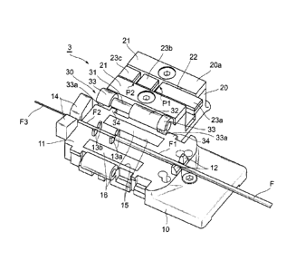
buffer optical fiber
placed on a holder base against the holder base.
[0003] However, when the tube of the loose buffer optical fiber has a
predetermined
hardness or higher, the existing grasping structure fails to grasp and fix in
place the optical-
fiber strand inserted into the tube even by elastically pressing the tube
portion against the
holder base. In view of this situation, in order to grasp and fix in place an
optical-fiber
strand, the optical-fiber strand, not the tube portion, has to be directly
grasped.
[0004] Generally, the ratio of the length of a bare fiber protruding from
the optical-
fiber strand to the length of an optical-fiber strand protruding from a tube
or a coating of an
optical fiber buffer differs between a loose buffer optical fiber and a tight
buffer optical
fiber. More specifically, the ratio of the exposed bare fiber to the exposed
optical fiber
strand is larger in a tight buffer optical fiber than in a loose buffer
optical fiber. Therefore,
if an existing grasping structure configured such that the optical-fiber
strand of a loose
buffer optical fiber is directly grasped is used for a tight buffer optical
fiber, the grasping
structure would grasp the bare fiber, thereby making it more likely to damage
the bare fiber.
2
Summary of Invention
[0005] An object of the present invention is to provide an optical fiber
holder that can hold
optical fibers while bare fibers are prevented from being damaged even when
the optical fibers
have different ratios of an exposed bare fiber to an exposed optical fiber
strand and to provide an
optical fiber fusion splicer including the optical fiber holder.
[0006] In view of the above object, the present invention provides an
optical fiber holder
that holds an optical fiber. The optical fiber holder includes a base
including a setting table on
which the optical fiber is placed so as to be oriented in a predetermined
direction; a cover
including a pressing member that presses the optical fiber placed on the
setting table against the
setting table and the cover is movable in the predetermined direction only
when the cover is in a
state of having been opened away from the base such that a back face of the
cover has become
substantially parallel to the setting table; and a connecting portion that
joins the base and the
cover together. The connecting portion joins the cover to the base such that
the cover is
openable away from and closeable over the base and movable in the
predetermined direction.
[0007] Preferably, the base includes a plurality of guides protruding from
the setting table,
the guides allowing the optical fiber to be positioned thereon so as to be
oriented in the
predetermined direction. Preferably, the connecting portion includes a
rotating shaft disposed
parallel to the predetermined direction, a tube-shaped portion integrated with
the base and into
which the rotating shaft is inserted, a shaft holder integrated with the cover
and holding the
rotating shaft, and a protrusion protruding from the base and the shaft holder
has a notch so as not
to interfere with the protrusion when the cover is in the state of having been
opened away from
the base such that the back face of the cover has become substantially
parallel to the setting table.
[0008] According to another aspect of the present invention, the present
invention also
provides an optical fiber fusion splicer including a pair of optical fiber
holders each
according to the present invention, the optical fiber holders being disposed
so as to face
CA 2823147 2017-06-14
3
each other; and a splicing portion that splices the optical fibers held by the
optical fiber holders
together.
[0009] According to the present invention, it may be possible that even
when optical fibers
have different ratios of the exposed bare fiber to the exposed optical fiber
strand, the optical
fibers can be held while bare fibers are prevented from being damaged.
Brief Description of Drawings
[0010] Figure 1 is a perspective view of an optical fiber fusion splicer
according to an
embodiment of the present invention.
[0011] Figure 2 is a perspective view of an optical fiber holder included
in the optical fiber
fusion splicer illustrated in Fig. 1 while the optical fiber holder is in an
open state.
[0012] Figure 3 is a perspective view of the optical fiber holder
included in the optical fiber
fusion splicer illustrated in Fig. 1 while the optical fiber holder is in a
closed state.
[0013] Figure 4 is a side view of the optical fiber holder included in
the optical fiber fusion
splicer illustrated in Fig. 1 while the optical fiber holder is in the closed
state.
[0014] Figure 5 is a schematic diagram illustrating how the position of a
cover of the optical
fiber holder is adjusted.
Description of Embodiments
[0015] Referring to the drawings, an embodiment of the present invention is
described
below. The drawings are provided for the illustration purpose and not for
limiting the scope of the
invention. The identical reference numerals denote the same parts throughout
the drawings in
order to avoid redundant description. Not all ratios between dimensions in the
drawings are
exact.
[0016] Figure 1 is a perspective view of an optical fiber fusion splicer 1
according to an
embodiment of the present invention. The optical fiber fusion splicer 1
includes a box-like
housing 2. A pair of optical fiber holders 3, a splicing portion 4, and
optical-fiber
reinforcement heaters 5 are disposed on an upper portion of the housing 2. The
optical
CA 2823147 2017-06-14
CA 02823147 2013-06-26
4
fiber holders 3 are disposed so as to face each other and hold optical fibers
to be spliced
together. The splicing portion 4 splices the optical fibers held by the
optical fiber holders
3 together. The optical-fiber reinforcement heaters 5 heat a fiber
reinforcement sleeve
that covers a fusion-spliced portion of the optical fibers and cause the fiber
reinforcement
sleeve to contract. The optical fiber fusion splicer 1 also includes a monitor
6, which
displays the state of fusion splicing of the optical fibers imaged by a camera
(not
illustrated) disposed inside the housing 2.
[0017] The splicing portion 4 includes a pair of fiber positioning
members 7, each of
which allows a distal end portion of the optical fiber held by a corresponding
one of the
optical fiber holders 3 to be positioned thereon. These fiber positioning
members 7 are
disposed between the pair of optical fiber holders 3. The splicing portion 4
also includes
a pair of arc electrodes 12 used to splice distal end portions of optical
fibers together by an
arc discharge. The arc electrodes 8 are disposed between the pair of fiber
positioning
members 7.
[0018] Figure 2 is a perspective view of one of the optical fiber holders 3
of the optical
fiber fusion splicer 1 while the optical fiber holder 3 is in an open state.
Figure 3 is a
perspective view of the optical fiber holder 3 while the optical fiber holder
3 is in a closed
state. Figure 4 is a side view of the optical fiber holder 3 while the optical
fiber holder 3
is in the closed state. Each optical fiber holder 3 includes a base 10, a
cover 20, and a
connecting portion 30.
[0019] The base 10 includes a setting table 11 on which an optical fiber
F is placed.
A pair of guiding portions 12, multiple (two, here) pairs of guide pieces 13a
and 13b, and a
pair of guiding portions 14 are disposed on the setting table 11. The guiding
portions 12
guide a tube portion Fl of the optical fiber F. The multiple pairs of guide
pieces 13a and
13b allow a distal end portion of the tube portion Fl to be positioned thereon
and guide an
optical-fiber strand F2 protruding from the distal end portion. The guiding
portions 14
guide a bare fiber F3 protruding from a distal end portion of the optical-
fiber strand F2.
[0020] The pair of guiding portions 12, the pairs of guide pieces 13a
and 13b, and the
pair of guiding portions 14 are arranged in order in the longitudinal
direction
(predetermined direction) of the base 10. Thus, the optical fiber F is placed
on the setting
CA 02823147 2013-06-26
table 11 so as to be oriented in the longitudinal direction of the base 10
with the support of
the guiding portions 12, the guide pieces 13a and 13b, and the guiding
portions 14.
[0021] Two grooves 15 that extend substantially parallel to each other
in the
longitudinal direction of the base 10 are formed in the setting table 11. The
grooves 15
5 are located on both sides of a center portion of the setting table 11 on
which the optical
fiber F is placed. A cuboid magnet 16 is disposed in each groove 15.
[0022] As described below, the cover 20 is openably and closeably joined
to the base
via a connecting portion 30. Consequently, the cover 20 can be switched to a
state of
having been opened away from the base 10 as illustrated in Fig. 2 or closed
over the base
10 10 as illustrated in Fig. 3.
[0023] Two metal plates 21 that extend in the longitudinal direction of
the base 10 are
attached to the cover 20. The metal plates 21 are located at positions
corresponding to the
respective magnets 16 when the cover 20 is in a state of having been closed
over the base
10. Thus, the cover 20 can be kept in the state of having been closed
over the base 10 due
to the magnetic force generated between the magnets 16 and the metal plates
21.
[0024] A groove 22 that extends in the longitudinal direction of the
base 10 is formed
in the center portion of the cover 20 so as to keep the metal plates 21
separated from each
other. The groove 22 is formed at a position corresponding to the position of
the optical
fiber F that is placed on the setting table 11 of the base 10 when the cover
20 is in the state
of having been closed over the base 10.
[0025] Pressing members 23a to 23c that press the optical fiber F
against the setting
table 11 are disposed in the groove 22. The pressing members 23a to 23c are
urged by
elastic bodies (not illustrated), such as springs, toward a back face (a face
that faces the
base 10) 20a of the cover 20. Thus, when the cover 20 is in the state of
having been
closed over the base 10, the pressing members 23a to 23c press the optical
fiber F placed
on the setting table 11 against the setting table 11 by the urging force of
the elastic bodies.
[0026] The pressing member 23a, the pressing member 23b, and the
pressing member
23c are arranged in this order in the longitudinal direction of the base 10
and are separated
from each other on at least a side near the back face 20a of the cover 20. A
gap portion
P1 between the pressing member 23a and the pressing member 23b is formed at
such a
position as to allow the guide pieces 13a to be inserted thereinto when the
cover 20 is
CA 02823147 2013-06-26
6
closed over the base 10. A gap portion P2 between the pressing member 23b and
the
pressing member 23c is formed at such a position as to allow the guide pieces
13a or the
guide pieces 13b to be inserted thereinto when the cover 20 is closed over the
base 10.
[0027] The pressing member 23a, the pressing member 23b, and the
pressing member
23c separately press the optical fiber F when the cover 20 is closed over the
base 10.
Therefore, the pressing member 23b and the pressing member 23c can press the
relatively
thin optical-fiber strand F2 of the optical fiber F while the pressing member
23a presses the
relatively thick tube portion Fl.
[0028] The connecting portion 30 includes a rotating shaft 31, a tube-
shaped portion
32, and shaft holders 33. The rotating shaft 31 is disposed on one side
portion of the base
10 so as to extend in the longitudinal direction of the base 10. The tube-
shaped portion
32 is formed so as to protrude from the one side portion of the base 10. The
shaft holders
33 are formed so as to protrude from end portions of the cover 20 located on
the base 10
side. The rotating shaft 31 is slidably inserted into the tube-shaped portion
32. The
shaft holders 33 hold and secure the both end portions of the rotating shaft
31 inserted into
the tube-shaped portion 32. In this manner, the connecting portion 30 joins
the cover 20
to the base 10 so that the cover 20 is rotatable (openable and closeable)
around the rotating
shaft 31.
[0029] Here, the connecting portion 30 joins the cover 20 to the base 10
such that
cover 20 is movable in the longitudinal direction of the base 10 with respect
to the base 10
by making the rotating shaft 31 slidable with respect to the tube-shaped
portion 32.
Particularly, the connecting portion 30 allows the cover 20 to move with
respect to the base
10 in the longitudinal direction of the base 10 only when the cover 20 is in
the state of
having been opened away from the base 10 such that the back face 20a of the
cover 20 has
become substantially parallel to the setting table 11 (that is, such that an
angle included
between the back face 20a and the setting table 11 has become substantially
180').
[0030] To this end, the connecting portion 30 includes a pair of
protrusions 34 formed
so as to protrude from the one side portion of the base 10. Each shaft holder
33 is shaped
like a tube having a notch 33a. The notch 33a is formed at such a position and
in such a
shape that the corresponding protrusion can pass therethrough when the cover
20 is opened
away from the base 10 such that the back face 20a of the cover 20 becomes
substantially
CA 02823147 2013-06-26
7
parallel to the setting table 11. Thus, the cover 20 becomes movable with
respect to the
base 10 in the longitudinal direction of the base 10 only when the cover 20 is
in the state of
having been opened away from the base 10 such that the back face 20a of the
cover 20 has
become substantially parallel to the setting table 11. Consequently, the cover
can be
prevented from being accidentally moved in the predetermined direction in the
course of
being opened and closed.
[0031] When the optical fiber F is to be held by the optical fiber
holder 3, first, as
illustrated in Fig. 2, the optical fiber F is placed on the setting table 11
of the base 10.
Here, the optical fiber F is placed so as to be oriented in the longitudinal
direction of the
base 10 with the support of the guiding portions 12, the guide pieces 13a and
13b, and the
guiding portions 14.
[0032] Subsequently, while the cover 20 is in the state of having been
opened away
from the base 10 such that the back face 20a of the cover 20 has become
substantially
parallel to the setting table 11, the position of the cover 20 in the
longitudinal direction of
the base 10 is adjusted. More specifically, the position of the cover in the
longitudinal
direction of the base 10 is adjusted so that the positions of the pressing
members 23a to 23c
are adjusted in accordance with the ratio of the exposed bare fiber F3 to the
exposed
optical fiber strand F2.
[0033] For example, when the optical fiber F is a loose buffer optical
fiber, the ratio of
the exposed bare fiber F3 to the exposed optical fiber strand F2 is relatively
small. In
other words, when the optical fiber F is a loose buffer optical fiber, the
optical-fiber strand
F2 is relatively long. Therefore, in order to press the optical-fiber strand
F2 by using the
pressing member 23b and the pressing member 23c, the cover 20 is moved toward
an end
(a front end) of the base 10 as illustrated in Fig. 5(a).
[0034] On the other hand, when the optical fiber F is a tight buffer
optical fiber, the
ratio of the exposed bare fiber F3 to the exposed optical fiber strand F2 is
relatively large.
In other words, when the optical fiber F is a tight buffer optical fiber, an
optical-fiber
strand F2 is short. Therefore, in order to press the tube portion F1 by using
the pressing
member 23a and the pressing member 23b, the cover 20 is moved toward a rear
end of the
base 10 as illustrated in Fig. 5(b).
CA 02823147 2013-06-26
8
[0035] When the cover 20 is then switched to the state of having been
closed over the
base 10 as illustrated in Fig. 3, the pressing members 23a to 23c press the
optical fiber F
against the setting table 11 to hold the optical fiber F.
[0036] As described above, in the optical fiber holder 3, the connecting
portion 30
joins the cover 20 to the base 10 such that the cover 20 is movable with
respect to the base
in the longitudinal direction of the base 10. Consequently, the pressing
members 23a
to 23c that press the optical fiber F are movable in the longitudinal
direction of the base 10.
[0037] Thus, by moving the pressing members 23a to 23c in accordance
with the ratio
of the exposed bare fiber F3 to the exposed optical fiber strand F2 (that is,
in accordance
10 with the length of the optical-fiber strand F2), the optical fiber F can
be held without the
bare fiber F3 being directly pressed. Consequently, even when optical fibers
having
different ratios of the exposed bare fiber F3 to the exposed optical fiber
strand F2, such as
a loose buffer optical fiber and a tight buffer optical fiber, are held, the
bare fibers can be
prevented from being damaged. Moreover, since the optical fiber fusion splicer
1
includes the above-described optical fiber holder 3, the optical fiber fusion
splicer 1 can
excellently fusion-splices the optical fibers together while the bare fibers
are prevented
from being damaged.
[0038] Thus far, the optical fiber holder and the optical fiber fusion
splicer according
to the embodiment of the present invention have been described. However, the
optical
fiber holder and the optical fiber fusion splicer according to the present
invention are not
limited to the optical fiber holder 3 and the optical fiber fusion splicer I
described above.
The optical fiber holder and the optical fiber fusion splicer according to the
present
invention may be ones obtained by modifying the optical fiber holder 3 and the
optical
fiber fusion splicer 1 within the scope not changing the gist of the claims.
For example,
in the above embodiment, the optical fiber holder 3 has been described as
being installed in
the optical fiber fusion splicer 1, but the present invention is not limited
to this. The
optical fiber holder 3 may be installed in other devices.
Citation List
Patent Literature
[0039] PTL 1: Japanese Patent Application Publication No. 2008-292523