Language selection

Search

Patent 2823156 Summary

Third-party information liability

Some of the information on this Web page has been provided by external sources. The Government of Canada is not responsible for the accuracy, reliability or currency of the information supplied by external sources. Users wishing to rely upon this information should consult directly with the source of the information. Content provided by external sources is not subject to official languages, privacy and accessibility requirements.

Claims and Abstract availability

Any discrepancies in the text and image of the Claims and Abstract are due to differing posting times. Text of the Claims and Abstract are posted:

  • At the time the application is open to public inspection;
  • At the time of issue of the patent (grant).
(12) Patent: (11) CA 2823156
(54) English Title: TAPER DOOR CONNECTOR STRATEGY
(54) French Title: STRATEGIE DE CONNECTEUR DE PORTE CONIQUE
Status: Granted
Bibliographic Data
(51) International Patent Classification (IPC):
  • B60J 5/04 (2006.01)
(72) Inventors :
  • ENCK, BRIAN (United States of America)
(73) Owners :
  • NAVISTAR DEFENSE, LLC (United States of America)
(71) Applicants :
  • INTERNATIONAL TRUCK INTELLECTUAL PROPERTY COMPANY, LLC (United States of America)
(74) Agent: FINLAYSON & SINGLEHURST
(74) Associate agent:
(45) Issued: 2019-06-25
(22) Filed Date: 2013-08-08
(41) Open to Public Inspection: 2014-02-28
Examination requested: 2018-05-15
Availability of licence: N/A
(25) Language of filing: English

Patent Cooperation Treaty (PCT): No

(30) Application Priority Data:
Application No. Country/Territory Date
13/596,584 United States of America 2012-08-28

Abstracts

English Abstract

A door support assembly for a motor vehicle is described. Generally speaking, the assembly includes a pin with a tapered section and being attached to the vehicle door, a passage with a mating surface for the tapered section fixed to the vehicle, and a latching mechanism configured to pull the vehicle door inward when engaged. When the latch mechanism is engaged, the assembly provides zero-gap with the door frame. The pin is tapered to a degree that it does not become wedged within the passage as the result of an explosive event.


French Abstract

Un ensemble de support de porte pour un véhicule à moteur est décrit. En règle générale, lensemble comprend une broche avec une section conique et étant fixée à la porte du véhicule, un passage avec une surface de contact pour la section conique fixée au véhicule, et un mécanisme de verrouillage conçu pour tirer la porte du véhicule vers lintérieur lorsque mis en prise. Lorsque le mécanisme de verrouillage est mis en prise, lensemble ne présente aucun écartement avec le cadre de porte. La broche est conique à un degré qui ne devient pas en biseau à lintérieur du passage à la suite dun évènement explosif.

Claims

Note: Claims are shown in the official language in which they were submitted.


CLAIMS
What is claimed is:
1. A vehicle door assembly comprising:
a vehicle door hinged along a first edge to a vehicle;
a door support pin attached to a second edge of the vehicle door;
a plate attached to the vehicle adjacent the second edge of the vehicle door
and having a
passage defined therein which corresponds to and allows a portion of the door
support pin to pass
there through; and
a latch mechanism configured to be manually engaged and disengaged with the
portion of
the door support pin which passes through the plate.
2. The vehicle door assembly of Claim 1, wherein the passage in the plate
has a mating
surface which matches the surface of the door support pin.
3. The vehicle door assembly of Claim 1, wherein the support pin comprises:
a base attaching the support pin to the door;
a tapered section which narrows in a direction opposite the base; and
a flange attached at the narrow of the tapered section and extending beyond a
diameter of the tapered section.
4. The vehicle door assembly of Claim 3, wherein the plate has a thickness
substantially
equal to a length of the tapered section of the door support pin.
5. The vehicle door assembly of Claim 1, wherein the latch mechanism is
configured to pull
the door support pin inward to a support frame when engaged.
6. The vehicle door assembly of Claim 3, wherein the latch mechanism is
configured to
engage the flange of the door support pin to pull the door inward when
engaged.
6


7. The vehicle door assembly of Claim 5, wherein the latch mechanism has a
slot therein
and the slot comprises a chamfered surface.
8. The vehicle door assembly of Claim 1, wherein the pin is comprised of a
high-strength
material.
9. The vehicle door assembly of Claim 3, wherein the pin is comprised of a
high-strength
material.
10. The vehicle door assembly of Claim 3, wherein the taper has a ratio in
the range from
about 1:1 to about 5:1.
11. The vehicle door assembly of Claim 3, wherein the taper has a ratio
greater than 5:1.
12. A method for maintaining operability of a vehicle access door in
response to a blast
event, the method comprising the steps of:
affixing at least one door support pin to a non-hinged edge of the door;
attaching a plate to the vehicle, the plate having at least one passage
defined thereon, with
each passage corresponding to and allowing a portion of a door support pin to
pass there through;
latching an end of the door support pin which passes through the passage;
wherein the support pin moves the door with the plate in response to a blast
event.
13. The method of Claim 12, wherein the support pin comprises:
a base attaching the support pin to the door;
a tapered section which narrows in a direction opposite the base; and
a flange attached at the narrow of the tapered section and extending beyond a
diameter of the tapered section.
7


14. The method of Claim 13, wherein the step of latching the end of the
door support pin
comprises the step of pulling the tapered section of the pin into engagement
with the passage of
the plate.
15. The method of Claim 14, wherein the tapered section has a ratio of
greater than 5:1.
8

Description

Note: Descriptions are shown in the official language in which they were submitted.


CA 02823156 2013-08-08
1
T A PER DOOR CONNECTOR STRATEGY
TECHNICAL FIELD
10001j The present device and methods relate to door latches. More
specifically, the device
relates to a door latch which operates during and after a blast event.
BACKGROUND
100021 In any attack on a military vehicle, the primary objective is always
the safety of
personnel within the vehicle. In furtherance of this objective, the vehicle
access points, such as
doors, are of critical concern. For example, during a blast event the doors
must provide sufficient
shielding of vehicle personnel by remaining closed, but also must remain
functional to provide
immediate exit from the vehicle after the event. Accordingly, door seals
should remain intact to
prevent gas ingress to the vehicle cabin, and door latches should remain
functional to prevent
trapping personnel within the vehicle cabin.
100031 The latch of FIG. 1 illustrates a typical combat latching mechanism
50. Several of
these combat latches may be located along the edge of a vehicle door with the
intention that it
acts much like a household deadbolt. That is, if anyone tries to enter, the
combat latch
mechanism 50 is fixed in place on the vehicle interior and requires mechanical
disengagement
from the inside to provide passage in or out. These latches are unlike a
regular door latch which
engages via springs and can be operated from the interior or exterior of the
vehicle.
100041 The combat lock mechanism 50 comprises linkage 52 attached to a
pivoting paddle
54. The linkage 52 is actuated to rotate the paddle 54 which then
engages/disengages with a slot
56 in the door frame when the door is closed, mechanically fixing the door
lock.

CA 02823156 2013-08-08
100051 When an extremely violent blast event occurs, such as an explosion,
all of the vehicle
door panels are designed to deflect to a point to blunt the blast. However,
such deflection can
also cause the paddle 54 to disengage with the slot 56 or to becomes bent. If
the paddle 54
disengages, the door can open, at least enough to allow gases to enter the
cabin. If the paddle 54
bends, it may not readily disengage when the occupants try to evacuate after
the event, trapping
them inside.
100061 These and other problems are solved by the present device and system
by providing a
door support assembly capable of withstanding a severe blast event without
compromising the
safety of the personnel and without hindering egress of that personnel after
the event.
SUMMARY
100071 Generally speaking, a vehicle door assembly is described having a
vehicle door
hinged along a first edge to a vehicle and a door support pin attached to a
second edge of the
vehicle door. A plate attached to the vehicle adjacent the second edge of the
vehicle door and
having a passage defined therein which corresponds to and allows a portion of
the door support
pin to pass there through, works to support the door. Finally, a latch
mechanism configured to be
manually engaged and disengaged with the portion of the door support pin which
passes through
the plate completes the assembly.
100081 In an embodiment of the assembly, the passage in the plate has a
mating surface
which matches the surface of the door support pin. Further, the support pin
includes a base
attaching the support pin to the door, a tapered section which narrows in a
direction opposite the
base, and a flange attached at the narrow of the tapered section and extending
beyond a diameter

CA 02823156 2013-08-08
of the tapered section. The taper of the tapered section has a ratio in the
range from about 1:1 to
about 5:1 to prevent binding.
100091 In use, the latch mechanism is configured to engage the flange of
the door support pin
to pull the door inward when engaged. Accordingly, the latch mechanism has a
slot therein and
the slot comprises a chamfered surface.
100101 Additional embodiments and features of the system can be understood
from the
appended drawings and the detailed description below.
BRIEF DESCRIPTION OF THE DRAWINGS
100iii FIG. 1 is a side view of a prior art door latching assembly;
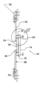
100121 FIG. 2 is a top view of a door support assembly illustrated in
accordance with the
disclosure;
100131 FIG. 3 is a close-up view of the features of the door support
assembly highlighted by
the circle of FIG. 2; and
100141 FIG. 4 is a side view of the latch mechanism of the present
assembly.
3

CA 02823156 2013-08-08
DETAILED DESCRIPTION
100151 With reference to FIGS. 2-4, an embodiment of the door support
assembly can be
most readily seen and understood. The assembly is generally indicated in the
appended drawings
by the numeral 10, and assembly components are consistently identified
throughout the drawing
figures and the following description. While the assembly 10 is described with
respect to a
military vehicle (not shown), it is understood that the application of the
assembly is much
broader.
[00161 FIG. 2 illustrates a top view of an embodiment of system 10
installed for use on a
double-door vehicle. As shown, the assembly 10 operates on a vehicle door 30
hinged along a
first edge via at least one high-strength steel hinge 32. The second (or
opposing) edge 34 of the
door is releasable to allow ingress and egress of personnel, for example. The
second edge abuts
the vehicle frame/body 36 to which it may be releasably coupled.
100171 The assembly comprises comprising a support pin 12, a lock plate 14
and a latching
mechanism 16. The pin 12, which is fixed to the second edge of the door 30,
has three sections:
a base, a tapered section, and a flanged section. One support pin 12 is
sufficient for most
applications, though a plurality of pins may be used, if necessary. The pin 12
is made from a
high-strength material which resists shearing, elongating, twisting and
generally deforming.
Likewise, the plate 14 and the latching mechanism 16 are also made from high-
strength steel or
the like.
100181 As shown in FIG. 3, the plate 14 includes a conical passage 20 which
has surfaces to
mate with the tapered portion of the pin 12. To prevent binding within the
passage 20, the taper
of pin 12 should be broad, for example, having a ratio greater than 5:1, and
including in the
4

CA 02823156 2013-08-08
range from 1:1 to about 5:1. The plate 14, once positioned to align the
passage 20 with the
support pin 12, is affixed to the vehicle body or sidewall 36.
100191 The latching mechanism 16 may operate and be used much like the
combat lock
mechanism 50 of FIG. 1. That is, the latching mechanism 16 works as a dead-
bolt for the door
30, to be engaged when in combat or similar situations. The latching mechanism
16 may be
engaged and disengaged via linkage 24 responsive to a mechanical lever (not
shown). The
latching mechanism 16 includes a latch 18 having a slotted opening 26. The
slotted opening 26
has a chamfered surface which draws the pin 12 inward as it is engaged.
100201 In use, the vehicle door 30 is closed pivoting at the hinged edge 32
until the second
edge 34 contacts the vehicle sidewall 36. The support pin 12 passes through
the passage 20 of
the plate 14 fixed on the interior of the vehicle sidewall 36. When desired,
the latch 18 of the
latching mechanism 16 may be rotated to engage the slotted opening 26 (FIG. 4)
with the support
pin 12 just below the flanged end. The chamfered surface of the slotted
opening 26 pulls the pin
12 inward to nest the tapered section within the conical passage 20 of the
plate 14. To unlatch
the latching mechanism 16 the latch 18 rotation is reversed. Once disengaged,
the vehicle door
30 may be opened for ingress or egress.

Representative Drawing
A single figure which represents the drawing illustrating the invention.
Administrative Status

For a clearer understanding of the status of the application/patent presented on this page, the site Disclaimer , as well as the definitions for Patent , Administrative Status , Maintenance Fee  and Payment History  should be consulted.

Administrative Status

Title Date
Forecasted Issue Date 2019-06-25
(22) Filed 2013-08-08
(41) Open to Public Inspection 2014-02-28
Examination Requested 2018-05-15
(45) Issued 2019-06-25

Abandonment History

There is no abandonment history.

Maintenance Fee

Last Payment of $263.14 was received on 2023-07-31


 Upcoming maintenance fee amounts

Description Date Amount
Next Payment if standard fee 2024-08-08 $347.00
Next Payment if small entity fee 2024-08-08 $125.00

Note : If the full payment has not been received on or before the date indicated, a further fee may be required which may be one of the following

  • the reinstatement fee;
  • the late payment fee; or
  • additional fee to reverse deemed expiry.

Patent fees are adjusted on the 1st of January every year. The amounts above are the current amounts if received by December 31 of the current year.
Please refer to the CIPO Patent Fees web page to see all current fee amounts.

Payment History

Fee Type Anniversary Year Due Date Amount Paid Paid Date
Registration of a document - section 124 $100.00 2013-08-08
Application Fee $400.00 2013-08-08
Maintenance Fee - Application - New Act 2 2015-08-10 $100.00 2015-06-19
Maintenance Fee - Application - New Act 3 2016-08-08 $100.00 2016-06-20
Maintenance Fee - Application - New Act 4 2017-08-08 $100.00 2017-06-16
Request for Examination $800.00 2018-05-15
Maintenance Fee - Application - New Act 5 2018-08-08 $200.00 2018-06-15
Registration of a document - section 124 $100.00 2019-03-13
Final Fee $300.00 2019-05-08
Maintenance Fee - Application - New Act 6 2019-08-08 $200.00 2019-06-19
Maintenance Fee - Patent - New Act 7 2020-08-10 $200.00 2020-07-15
Maintenance Fee - Patent - New Act 8 2021-08-09 $204.00 2021-07-14
Maintenance Fee - Patent - New Act 9 2022-08-08 $203.59 2022-07-25
Maintenance Fee - Patent - New Act 10 2023-08-08 $263.14 2023-07-31
Owners on Record

Note: Records showing the ownership history in alphabetical order.

Current Owners on Record
NAVISTAR DEFENSE, LLC
Past Owners on Record
INTERNATIONAL TRUCK INTELLECTUAL PROPERTY COMPANY, LLC
Past Owners that do not appear in the "Owners on Record" listing will appear in other documentation within the application.
Documents

To view selected files, please enter reCAPTCHA code :


To view images, click a link in the Document Description column. To download the documents, select one or more checkboxes in the first column and then click the "Download Selected in PDF format (Zip Archive)" or the "Download Selected as Single PDF" button.

List of published and non-published patent-specific documents on the CPD .

If you have any difficulty accessing content, you can call the Client Service Centre at 1-866-997-1936 or send them an e-mail at CIPO Client Service Centre.


Document
Description 
Date
(yyyy-mm-dd) 
Number of pages   Size of Image (KB) 
Abstract 2013-08-08 1 14
Description 2013-08-08 5 176
Claims 2013-08-08 3 73
Drawings 2013-08-08 2 30
Representative Drawing 2014-01-30 1 3
Cover Page 2014-02-06 2 33
Request for Examination 2018-05-15 1 37
Final Fee 2019-05-08 1 36
Representative Drawing 2019-05-28 1 4
Cover Page 2019-05-28 1 29
Assignment 2013-08-08 6 243