Note: Descriptions are shown in the official language in which they were submitted.
ANGIOGRAPHY CATHETER
BACKGROUND
Field
[0002] The present application generally relates to devices and
methods for
locating the proper position to perform a cardiac procedure and/or capturing
embolic debris
during a cardiac procedure.
Description of the Related Art
[0003] During percutaneous cardiac procedures, precise positioning
of various
instruments and devices can be important. For example, when performing a
percutaneous
valve replacement procedure, the valve is generally placed no more than 4-6
millimeters
(mm) below the lower border of the aortic annulus. Placing the valve
prosthesis too low or
too high can result in severe leaking of the valve, which in some cases can be
fatal.
Therefore, it can be important to identify the lower border of the annulus to
use as a reference
point. A pigtail catheter may be used to inject a contrast agent to allow for
visualization for
proper positioning. Pigtail catheters may include a coiled distal portion and
a plurality of
small holes in the catheter side walls. The small holes allow for the
introduction of contrast
materials into the body for imaging purposes or drainage of fluids from the
body. The coiled
distal portion helps hold the catheter is place and can slow the flow of
contrast fluids from
the catheter lumen to avoid causing internal injuries or poor imaging results.
[0004] A potential complication of cardiac procedures such as valve
replacement
and repair is that plaque, calcium, and/or thrombi in the vessels, valves,
and/or cardiac
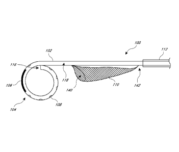
chambers can be dislodged and cause an embolism. Indeed, 2.9%-6.7% of patients
-1-
CA 2823198 2018-04-30
CA 02823198 2013-06-26
WO 2012/094195 PCT/US2011/067440
undergoing transfemroal transcatheter aortic-valve implantation (TAVI) have a
stroke within
30 days, and even more (4.5%-10.6%) have a stroke within a year, often leading
to death.
There are a few devices on the market designed to protect the carotid arteries
from emboli;
however, these devices have various disadvantages. For example, the Embrella
Embolic
Deflector , available from Edwards Lifesciences of Irvine, California,
deflects emboli from
the carotid arteries into the descending aorta, but does not trap the emboli,
so there is a risk of
embolisms in other areas of the body. The EMBOL-X , also available from
Edwards
Lifesciences, employs a filtering screen, but it is designed for use in open
heart procedures.
Additionally, the use of multiple devices, for example a catheter for
visualization and a
separate filter device, lengthens the procedure time and increases the risk of
complications to
the patient.
SUMMARY
[0005] A vascular device includes a pigtail and/or an embolic protection
device.
A pigtail is configured to curl at the distal end of the catheter, for example
when there is no
guidewire in a lumen of the catheter. The pigtail includes a radiopaque marker
viewable on
x-rays or other radiation devices. The radiopaque marker is on the distal-most
section of the
curled pigtail in the form of a longitudinal marker, multiple bands, etc. The
pigtail may
include apertures to dispense drugs and/or contrast agents through the lumen.
An embolic
protection device includes a self-expanding filter coupled to the catheter and
an outer sheath
movable with respect to the filter and the catheter. The outer sheath holds
the filter in a
collapsed configuration when surrounding the filter and is proximally
retracted to deploy the
filter. The outer sheath may recapture the filter and any debris captured
therein by being
distally advanced. The filter and outer sheath might both be movable with
respect to the
catheter, for example to be able to move the filter longitudinally without
having to move the
entire catheter longitudinally. The combination of the pigtail and the embolic
protection
device in the same vascular device may provide the benefits of both devices
individually, as
well as a synergistic effect. For example, expansion of the filter may help to
anchor the
pigtail into position to provide a more accurate position of the catheter than
if the position of
the pigtail could be influenced by blood flow, tissue movement, etc. In a
valve replacement
-2-
CA 02823198 2013-06-26
WO 2012/094195 PCT/US2011/067440
procedure, anchoring of the pigtail and more accurate positioning of the
catheter may in turn
help ensure that the valve prosthesis is properly positioned and stabilized.
For another
example, the position of the pigtail may ensure that the filter is being
properly positioned.
[0006] To use these types of devices, a guidewire is inserted through
the patient's
skin and into a body lumen such as a femoral, radial, or brachial artery and
steered near a
target site. The guidewire is inserted into a lumen of the device, and the
device is pushed or
tracked over the guidewire to the target site. When the guidewire is retracted
from at least the
distal portion of the catheter, the pigtail assumes the generally arcuate
shape. The radiopaque
marker on the pigtail is used to visualize and position the catheter. Once the
catheter is in
position, the outer sheath is retracted to deploy the filter spanning across
the vessel. The user
can then perform a procedure such as valve replacement, valve repair, radio
frequency
ablation, etc. When the procedure is completed, the outer sheath is advanced
to recapture the
filter and any debris trapped in the filter. The device is then retracted,
with the pigtail being
atraumatic to vessels during retraction.
[0007] In some embodiments, an embolic protection device comprises a
catheter
having a proximal end a distal end. A lumen extends from the proximal end of
the catheter to
the distal end of the catheter. The lumen is configured to house a guidewire.
A distal portion
of the catheter is configured to assume a generally arcuate shape that is at
least a semi-circle.
The distal portion of the catheter includes a longitudinally-extending
radiopaque marker
configured to be arcuate and on a distal-most section of the catheter when the
distal portion is
in the generally arcuate shape. The device further comprises a self-expanding
embolic filter
coupled to the catheter proximal to the distal portion. The embolic filter has
a generally
conical shape extending between a distal opening and a closed proximal end.
The device also
includes a deployment mechanism circumferentially disposed around at least a
portion of the
catheter and longitudinally movable with respect to the catheter. The
deployment mechanism
is configured to contain the embolic filter in a collapsed configuration. The
embolic filter is
configured to self-expand when the deployment mechanism is longitudinally
proximally
retracted.
[0008] In some embodiments, an angiography catheter comprises a catheter
having a proximal end and a distal end. A lumen extends from the proximal end
of the
-3-
CA 02823198 2013-06-26
WO 2012/094195 PCT/US2011/067440
catheter to the distal end of the catheter and is configured to house a
guidewire. A distal
portion of the catheter is configured to assume a generally arcuate shape that
is at least a
semi-circle. The distal portion of the catheter includes a longitudinally-
extending radiopaque
marker configured to be arcuate and on a distal-most section of the catheter
when the distal
portion is in the generally arcuate shape.
[0009] In some embodiments, an embolic protection device comprises a
catheter
having a proximal end and a distal end. The device further comprises a self-
expanding
embolic filter coupled to a side of the catheter. The embolic filter has a
generally conical
shape and extends between a distal opening and a closed proximal end. The
device also
includes an outer sheath that is longitudinally movable with respect to the
embolic filter. The
outer sheath is configured to contain the embolic filter in a collapsed state
when the sheath is
at least partially around the embolic filter. The embolic filter is configured
to self-expand
when the outer sheath is longitudinally proximally retracted.
[0010] In some embodiments, an embolic protection device comprises a
catheter
having a proximal end a distal end. A lumen extends from the proximal end of
the catheter to
the distal end of the catheter. The lumen is configured to house a guidewire.
A distal portion
of the catheter is configured to assume a generally arcuate shape that is at
least a semi-circle.
The distal portion of the catheter includes a longitudinally-extending
radiopaque marker
configured to be arcuate and on a distal-most section of the catheter when the
distal portion is
in the generally arcuate shape. The device further comprises a self-expanding
deflector
coupled to a side of the catheter and having a longitudinal axis parallel to a
longitudinal axis
of the catheter. The device also includes a deployment mechanism
circumferentially
disposed around at least a portion of the catheter and longitudinally movable
with respect to
the catheter. The deployment mechanism is configured to contain the deflector
in a collapsed
configuration. The deflector is configured to self-expand when the deployment
mechanism is
longitudinally moved.
[0011] In some embodiments, an embolic protection device comprises a
catheter
having a proximal end and a distal end. The device comprises a deflector
coupled to a side of
the catheter. The deflector has a longitudinal axis parallel to a longitudinal
axis of the
catheter. The device also includes an outer sheath that is longitudinally
movable with respect
-4-
CA 02823198 2013-06-26
WO 2012/094195 PCT/US2011/067440
to the deflector. The outer sheath is configured to contain the deflector in a
collapsed state
when the sheath is at least partially around the deflector. The deflector is
configured to self-
expand when the outer sheath is longitudinally moved.
[0012] In some embodiments, an embolic protection device comprises a
catheter
having a proximal end and a distal end. The device comprises a deflector
coupled to a side of
the catheter. The deflector has a longitudinal axis parallel to a longitudinal
axis of the
catheter. The device further comprises a self-expanding embolic filter coupled
to the
catheter. The embolic filter has a generally conical shape and extends between
a distal
opening and a closed proximal end. The device also includes an outer sheath
that is
longitudinally movable with respect to the deflector and embolic filter. The
outer sheath is
configured to contain the deflector and embolic filter in a collapsed state
when the sheath is
at least partially around the deflector and embolic filter. The deflector and
embolic filter are
configured to self-expand when the outer sheath is longitudinally moved.
[0013] In some embodiments, a method of capturing embolic debris
comprises
inserting a distal end of an angiography catheter into a body lumen by
tracking a lumen of the
catheter over a guidewire percutaneously inserted into the body lumen. The
angiography
catheter has a proximal end and a distal end, and the lumen extends from the
proximal end to
the distal end. A distal portion of the angiography catheter includes a
longitudinally-
extending radiopaque marker. A self-expanding embolic filter is attached to a
side of the
catheter proximal to the distal portion. The angiography catheter also
includes an outer
sheath that contains the embolic filter in a collapsed configuration. When the
guidewire is
removed from the distal portion of the catheter, the distal portion assumes a
generally arcuate
shape. The method further comprises positioning the catheter by visualizing
the radiopaque
marker with an imaging technique and longitudinally proximally retracting the
outer sheath,
allowing the embolic filter to assume an expanded, deployed configuration
having a distal
opening substantially spanning the body lumen.
[0014] For purposes of summarizing the disclosure and the advantages
achieved
over the prior art, certain objects and advantages are described herein. Of
course, it is to be
understood that not necessarily all such objects or advantages need to be
achieved in
accordance with any particular embodiment. Thus, for example, those skilled in
the art will
-5-
CA 02823198 2013-06-26
WO 2012/094195 PCT/US2011/067440
recognize that the disclosure may be embodied or carried out in a manner that
achieves or
optimizes one advantage or group of advantages as taught or suggested herein
without
necessarily achieving other objects or advantages as may be taught or
suggested herein.
[0015] All of these embodiments are intended to be within the scope of
the
disclosure herein. These and other embodiments will become readily apparent to
those
skilled in the art from the following detailed description having reference to
the attached
figures, the disclosure not being limited to any particular disclosed
embodiment(s).
BRIEF DESCRIPTION OF THE DRAWINGS
[0016] These and other features, aspects, and advantages of the present
disclosure
are described with reference to the drawings of certain embodiments, which are
intended to
schematically illustrate certain embodiments and not to limit the invention.
[0017] FIGS. 1A and 1B show partial side views of an example embodiment
of an
embolic protection device;
[0018] FIGS. 1C and 1D show partial side views of another example
embodiment
of an embolic protection device;
[0019] HG. 2A is a partial side view of an example embodiment of an
angiography catheter;
[0020] FIGS. 2B-2E are partial side views of other example embodiments
of an
angiography catheter;
[0021] FIGS. 3A and 3B are partial side views of an example embodiment
of an
embolic protection device;
[0022] FIGS. 4A-4D are partial side views of another example embodiment
of an
embolic protection device;
[0023] FIGS. 5A and 5B show partial side views of an example embodiment
of an
alternative deployment mechanism for an embolic protection device;
[0024] FIG. 5C is an example embodiment of a transverse cross-sectional
view of
the deployment mechanism for the embolic protection device of FIGS. 5A and 5B
along the
line 5C-5C in PIG. 5B;
-6-
CA 02823198 2013-06-26
WO 2012/094195 PCT/US2011/067440
[0025] FIG. 5D shows a partial side view of the deployment mechanism for
the
embolic protection device of FIGS. 5A-5C;
[0026] FIG. 5E shows a partial top view of the deployment mechanism for
the
embolic protection device of FIGS. 5A-5D;
[0027] FIGS. 6A and 6B are partial side views of another example
embodiment of
an embolic protection device;
[0028] FIGS. 7A and 7B are partial side views of another example
embodiment of
an embolic protection device;
[0029] FIG. 7C is a bottom view of the embolic protection device of
FIGS. 7A
and 7B;
[0030] FIGS. 8A-8D are partial side views of another example embodiment
of an
embolic protection device;
[0031] FIG. 9 is a partial side view of another example embodiment of an
embolic
protection device;
[0032] FIGS. 10A-10D show an example embodiment of a method of capturing
embolic debris using an embolic protection device;
[0033] FIG. 11 shows an example embodiment of a method of deflecting
embolic
debris using an embolic protection device;
[0034] FIG. 12 shows another example embodiment of a method of
deflecting
embolic debris using an embolic protection device; and
[0035] FIG. 13 shows an example embodiment of a method of deflecting and
capturing embolic debris using an embolic protection device and deflector
device.
DETAILED DESCRIPTION
[0036] Although certain embodiments and examples are described below,
those of
skill in the art will appreciate that the disclosure extends beyond the
specifically disclosed
embodiments and/or uses and obvious modifications and equivalents thereof.
Thus, it is
intended that the scope of the disclosure herein disclosed should not be
limited by any
particular embodiments described below.
-7-
CA 02823198 2013-06-26
WO 2012/094195 PCT/US2011/067440
[0037] Figures
1A-1D illustrate example embodiments of an embolic protection
device 100. The device 100 comprises a pigtail catheter 102 having a proximal
end 114,
distal end 116, and a lumen 118 extending from the proximal end 114 to the
distal end 116.
The lumen 118 is configured to house a guidewire 740 (Figures 7A and 7B). The
pigtail
catheter 102 includes a distal portion 104 configured to assume a generally
arcuate shape
being at least a semi-circle. A side wall of the catheter 102 includes at
least one aperture 108
in the distal portion 104 configured to deliver fluids. The apertures 108 (the
plural intended
to include embodiments in which the distal portion includes one aperture 108)
are in fluid
communication with the lumen 118. The distal portion 104 of the catheter 102
includes a
longitudinally-extending radiopaque marker 106 that is configured to be
arcuate and on the
distal-most section of the catheter 102 when the distal portion 104 is in the
generally arcuate
shape. The device 100 further comprises a self-expanding embolic filter 110
and an outer
sheath 112. The embolic filter 110 is coupled to a side of the catheter 102
proximal to the
distal portion 104. When in an expanded configuration, the embolic filter 110
has a generally
conical shape extending proximally from a distal opening 140 to a closed
proximal end 142.
The outer sheath 112 is configured to be circumferentially around at least a
portion of the
catheter 102 and the embolic filter 110. The outer sheath 112 is configured to
contain the
embolic filter 110 in a collapsed configuration when around the embolic filter
110. The outer
sheath 112 is longitudinally movable with respect to the catheter 102, and can
be moved
proximally to release the embolic filter 110 and moved distally to recapture
the embolic filter
110 and embolic material in the embolic filter 110. The embolic filter 110 is
configured to
self-expand upon longitudinal proximal retraction of the outer sheath. A
device according to
the disclosure herein can comprise some or all of the features of the embolic
protection
device 100 shown in Figures 1A-1D, and is described herein in various
combinations and
subcombinations.
[0038] The
pigtail catheter 102 may comprise a flexible material so as to be
maneuverable within a body lumen as described herein. For example, in some
embodiments,
the catheter 102 comprises a polymer (e.g., polyurethane, silicone, latex,
polytetrafluoroethylene (P _________________________________________ 11E), a
plastic material, etc.). In some embodiments, the catheter
102 comprises a metal-reinforced plastic (e.g., including nitinol, stainless
steel, etc.). Other
-8-
CA 02823198 2013-06-26
WO 2012/094195 PCT/US2011/067440
materials are also possible. In some embodiments, the catheter 102 does not
comprise latex,
which may cause allergic reactions in some patients. In some embodiments, the
catheter 102
comprises braid-reinforced tubing to advantageously increase the strength of
the catheter 102.
In some embodiments, the catheter 102 comprises a braided catheter shaft
including a layer of
braided wire between two layers of catheter tubing, which may increase the
strength of the
catheter 102. In some embodiments, the catheter 102 does not include a braided
layer, which
may increase the flexibility of the catheter 102. In some embodiments, the
catheter 102
comprises a lubricious coating, for example a coating having a low friction
coefficient, to
advantageously allow for smoother navigation through tortuous vasculature. In
some
embodiments, the catheter 102 coating has anti-thrombotic properties to
advantageously
inhibit thrombus formation. In some embodiments, the catheter 102 has a size
(i.e., outside
diameter) between about 6 French and about 9 French (approx. between about 2
mm and
about 3 mm). Other sizes are also possible, for example depending on the size
of the target
body lumen of a particular patient. In some embodiments, the catheter 102 has
a length
between about 65 centimeters (cm) and about 135 cm. Other lengths are also
possible, for
example to allow for insertion of the catheter 102 in the femoral, brachial,
or radial artery.
The catheter 102 can be manufactured, for example, by extrusion, injection
molding, or
another suitable process.
[0039] The radiopaque marker 106 extends longitudinally along a section
of the
distal portion 104 of the catheter 102. When the distal portion 104 is in the
generally arcuate
shape, the radiopaque marker 106 is also generally arcuate and on a distal-
most section of the
catheter 102. In some embodiments, the radiopaque marker 106 has a length of
about 1 cm.
The radiopaque marker 106 comprises a radiopaque material, for example
platinum,
tantalum, tungsten, palladium, and/or iridium. Other radiopaque materials are
also possible.
In some embodiments, a material may be considered radiopaque, for example, if
the average
atomic number is greater than 24, if the density is greater than about 9.9
g/cm3, etc.
[0040] The embolic filter 110 has a generally conical shape (e.g.,
conical,
frustoconical, etc.) and is coupled (e.g., by adhering, welding, soldering,
coupling using a
separate component, combinations thereof, and the like) to a side of catheter
102. As shown
in Figures 1B and 1D, the embolic filter 110 includes a distal opening 140 and
extends
-9-
CA 02823198 2013-06-26
WO 2012/094195 PCT/US2011/067440
proximally from the distal opening 140 to a closed proximal end 142. In some
embodiments,
the distal opening 140 of the embolic filter 110 has a diameter of about 4.5
cm. The embolic
filter 110 can be made in different sizes having different diameters for
patients with different
sized blood vessels. In some embodiments, the shape of the distal opening 140
of the
embolic filter 110 is circular, oval, elliptical, oblong, egg-shaped,
combinations thereof, and
the like. In some embodiments, the embolic filter 110 comprises a shape memory
material,
for example including nitinol, chromium cobalt, and/or alloys such as MI)35N,
35NLT,
Elgiloy, etc. In some embodiments, the embolic filter 110 comprises a braided
mesh. In
some embodiments, the embolic filter 110 comprises a porous membrane, for
example a
semi-permeable polyurethane membrane. In some embodiments, the embolic filter
110 is
laser cut from a tube or a sheet. In some embodiments, the distal opening 140
of the embolic
filter 110 is attached to a self-expanding frame, for example a nitinol frame.
In some
embodiments, the embolic filter 110 comprises an anti-thrombogenic coating
(e.g.,
comprising heparin or a thrombin or platelet inhibitor) to advantageously
reduce
thrombogenicity. The embolic filter 110 is configured to self-expand to a
radially expanded,
open configuration, shown in Figures 1B and 1D, when not confined by, for
example, an
outer sheath 112.
[0041] In some embodiments, for example as illustrated in Figures 1A and
1B, the
embolic filter 110 is coupled to the catheter 102 on the side of the catheter
facing the distal
portion 104 when the distal portion 104 is in the generally arcuate shape. In
some
embodiments, for example as illustrated in Figures 1C and 1D, the embolic
filter 110 is
coupled to the catheter 102 on the side of the catheter facing away from the
distal portion 104
when the distal portion 104 is in the generally arcuate shape. The embolic
filter 110 can also
be coupled to any other side of the catheter 102 (e.g., orthogonal to a plane
of the arcuate
member). In some embodiments, the embolic filter 110 is coupled to the
catheter 102 along
the entire length of the embolic filter 110. In some embodiments, the embolic
filter 110 is
coupled to the catheter 102 at the proximal and/or distal ends of the embolic
filter 110 and/or
at any other points there between.
[0042] The outer sheath 112 comprises a hollow tube configured to
circumferentially surround at least a portion of the catheter 102. Outer
sheath 112 is
-10-
CA 02823198 2013-06-26
WO 2012/094195 PCT/US2011/067440
longitudinally movable with respect to the catheter 102 and is configured to
at least partially
contain (e.g., contain) the embolic filter 110 in a collapsed configuration
when
circumferentially surrounding the embolic filter 110, for example, as shown in
Figures 1A
and IC. The outer sheath 112 is longitudinally proximally retractable to
release the embolic
filter 110. The embolic filter 110 self-expands to the expanded, open
configuration when not
contained by the outer sheath 112. In some embodiments, the outer sheath 112
extends
proximally to the proximal end 114 of the catheter 102 so that the user can
grasp and
manipulate the outer sheath 112 directly. In some embodiments, the outer
sheath 112 extends
proximally over only a portion of the catheter 102, and a secondary device
(e.g., a push-rod
such as found in stent deployment systems) is coupled to the outer sheath 112
(e.g., to the
proximal end of the outer sheath 112) to allow for indirect manipulation of
the outer sheath
112. Manipulation of the outer sheath 112 may be mechanical, electronic,
manual,
combinations thereof, and the like.
[0043] Figure 2A illustrates an example embodiment of an angiography
catheter
200. The illustrated embodiment includes a flexible pigtail-type catheter 202
having a
proximal end 214, distal end 216, and a lumen 218 extending from the proximal
end 214 to
the distal end 216. The lumen 218 is configured to house a guidewire 740
(Figures 7A and
7B). The catheter 202 has a distal portion 204 configured to assume a
generally arcuate
shape and a radiopaque marker 206 on the distal portion 204.
[0044] The catheter 202 may comprise a flexible material so as to be
maneuverable within a body lumen as described herein. For example, in some
embodiments,
the catheter 202 comprises a polymer (e.g., polyurethane, silicone, latex,
polytetrafluoroethylene (PTFE), a plastic material, etc.). In some
embodiments, the catheter
202 comprises a metal-reinforced plastic (e.g., including nitinol, stainless
steel. etc.). Other
materials are also possible. In some embodiments, the catheter 202 does not
comprise latex,
which may cause allergic reactions in some patients. In some embodiments, the
catheter 202
comprises a braided catheter shaft including a layer of braided wire between
two layers of
catheter tubing, which may increase the strength of the catheter 202. In some
embodiments,
the catheter 202 does not included a braided layer, which may increase the
flexibility of the
catheter 202. In some embodiments, the catheter 202 comprises a lubricious
coating, for
-11-
CA 02823198 2013-06-26
WO 2012/094195 PCT/US2011/067440
example a coating having a low friction coefficient, to advantageously allow
for smoother
navigation through tortuous vasculature. In some embodiments, the catheter 202
coating has
anti-thrombotic properties, to advantageously inhibit thrombus formation.
In some
embodiments, the catheter 202 has a size (i.e., outside diameter) between
about 6 French and
about 9 French (approx. between about 2 mm and about 3 mm). Other sizes are
also
possible, for example depending on the size of the target body lumen of a
particular patient.
In some embodiments, the catheter 202 has a length between about 65 cm and
about 135 cm.
Other lengths are also possible, for example to allow for insertion of the
catheter 102 in the
femoral, brachial, or radial artery. The catheter 202 can he manufactured, for
example, by
extrusion, injection molding, or another suitable process.
[0045] As shown
in Figure 2A, a distal portion 204 of the catheter 202 is
configured to assume a generally arcuate shape like a pigtail catheter. When a
guidewire is in
the lumen 218, the guidewire substantially straightens the distal portion 204
of the catheter
202, allowing the catheter 202 to maneuver through body lumens as described
herein. When
the guidewire is withdrawn from at least the distal portion 204 of the
catheter 202 as
described herein, the distal portion 204 assumes the generally arcuate shape.
In some
embodiments, the generally arcuate shape is at least about a semi-circle. In
some
embodiments, the generally arcuate shape is at least about three-quarters of a
circle. In some
embodiments, the generally arcuate shape is at least about 350 . In some
embodiments, the
generally arcuate shape is at least about a full circle. In some embodiments,
the generally
arcuate shape is greater than about 90'. Non-circular arcuate shapes (e.g.,
oval, oblong,
elliptical, egg-shaped, spiral, etc.) are also possible, and descriptions of
the terms circle,
diameter, and the like herein should be interpreted in view of the arcuate
shape of the distal
portion 204. In some embodiments, the distal portion 204 of the catheter 202
has a diameter
of less than about 1 cm when the distal portion 204 is in the generally
arcuate shape. In some
embodiments, the diameter of the distal portion 204 is less than about 0.75
cm. In some
embodiments, for example when the angiography catheter 200 is used during a
valve
replacement procedure, a diameter of less than about 0.75 cm for the distal
portion 204 can
facilitate placement of the distal portion 204 within or adjacent to a
noncoronary cusp of a
patient.
-12-
CA 02823198 2013-06-26
WO 2012/094195 PCT/US2011/067440
[0046] In some embodiments, the proximal end 214 of the catheter 202 is
configured to be coupled to a contrast material injector and the lumen 218 is
also configured
to provide a flow path for contrast material from the proximal end 214 to the
distal end 216
of the catheter 202. For example, the proximal end 214 may include a Luer or
other fitting.
A side wall of the catheter 202 may include at least one aperture 208 in the
distal portion 204.
The aperture 208 is in fluid communication with the lumen 218, so that
contrast material,
drugs such as anti-thrombotics, etc. injected into the lumen 218 can be
dispersed from the
aperture 208, and optionally an opening at the distal end 216 of the catheter
202. In some
embodiments, the distal end 216 is closed, for example being configured to
inwardly collapse
when not held open by a guidewire. In some embodiments, the distal end 216 is
partially
open to allow for pressure measurements.
[0047] The embodiment of angiography catheter 200 illustrated in Figure
2A
comprises a radiopaque marker 206. The radiopaque marker 206 comprises a
radiopaque
material, for example platinum, tantalum, tungsten, palladium, and/or iridium.
Other
radiopaque materials are also possible. In some embodiments, a material may be
considered
radiopaque, for example, if the average atomic number is greater than 24, if
the density is
greater than about 9.9 g/cm3, etc.
[0048] As explained herein, during certain cardiac procedures, precise
placement
of instruments and devices can be important. For example, when performing a
percutaneous
cardiac valve replacement procedure, the replacement valve device should be
placed no more
than about 4-6 mm below the lower border of the aortic annulus. Therefore, the
user can
preferably identify the lower border of the annulus to use as a reference
point. The
radiopaque marker 206 advantageously allows the user to define and visualize
the lower
border of the annulus or other anatomic landmarks. A typical pigtail catheter
without a
radiopaque marker can be used for visualization during a procedure through the
injection of
contrast material. However, a radiopaque marker or markers on the catheter
itself can
advantageously reduce contrast load and allow uninterrupted identification of
the lower
border of the aortic annulus or other anatomic landmarks.
[0049] The size and positioning of radiopaque marker 206 may provide
additional
benefits. For example, making the entire distal portion 204 of the catheter
202 radiopaque
-13-
CA 02823198 2013-06-26
WO 2012/094195 PCT/US2011/067440
could result in the distal portion 204 being too stiff for maneuverability and
assuming the
arcuate shape. The radiopaque marker 206 illustrated in Figure 2A extends
longitudinally
along the outer curvature of the distal portion 204 of the catheter 202
similar to the
radiopaque marker 106 shown in Figures 1A- ID and described herein. When the
distal
portion 204 of the catheter 202 is substantially straight (e.g., due to a
guidewire being in the
lumen 218), the distal end 216 of the catheter 202 is the distal-most section
of the catheter
202. When the distal portion 204 of the catheter 202 assumes the generally
arcuate shape, the
distal end 216 of the catheter 202 curves at least partially proximally, so
the distal end 216 is
not the distal-most section of the catheter 202. Rather, the distal-most
section of the catheter
202 the section of the catheter 202 beyond which no other section of the
catheter 202 is
distal, which is the bottom curved section of the generally arcuate distal
portion 204. The
radiopaque marker 206 of Figure 2A is configured to be on the distal-most
section of the
catheter 202 when the distal portion 204 is in the generally arcuate shape.
This configuration
may provide the unique advantage of precisely identifying the distal-most edge
of the catheter
202 when the distal portion 204 is in the generally arcuate shape, thereby
allowing the user to
define an anatomic landmark, e.g., the lower border of the aortic annulus. In
some
embodiments, the radiopaque marker 206 has a length of about 1 cm. In some
embodiments,
the radiopaque marker 206 has a length of about 0.8 cm. In some embodiments,
the
radiopaque marker 206 has a length of about 0.5 cm. Other lengths of the
radiopaque marker
206 are also possible.
[0050] Figures 2B and 2C illustrate example embodiments of a radiopaque
marker 206. Figure 2B illustrates an embodiment in which the radiopaque marker
206 is
generally arcuate and configured to be on the distal-most section of the
catheter 202 when the
distal portion 204 is in the generally arcuate shape. In the embodiment
illustrated in Figure
2B, the radiopaque marker 206 is configured to be on the inner curvature of
the distal-most
section of the catheter 202 when the distal portion 204 is in the generally
arcuate shape.
Certain such embodiments may advantageously inhibit contact of body tissue by
the
radiopaque marker 206, which may be harder than the material of the catheter
202. Figure
2C illustrates an embodiment in which the radiopaque marker 206 comprises a
plurality of
radiopaque markers 206 transversely at least partially (e.g., fully)
encircling the catheter 202.
-14-
CA 02823198 2013-06-26
WO 2012/094195 PCT/US2011/067440
The radiopaque markers 206 are configured to be on the distal-most section of
the catheter
202 when the distal portion 204 is in the generally arcuate shape. Certain
such embodiments
may advantageously show a three-dimensional view of the distal-most section of
the catheter
202 and/or may be visible from various perspectives. Figure 2C shows six
radiopaque
markers 206; however, more or fewer radiopaque markers 206 are possible.
Spacing and/or
thickness of the radiopaque markers 206 may be consistent or may vary from
proximal to
distal, towards a center or edge of the radiopaque marker 206, etc.
Configurations of
radiopaque markers 206 other than those shown in Figures 2A-2C are also
possible.
[0051] In some embodiments, for example as shown in Figure 2A, the
apertures
208 are on an outer curved wall of the distal portion 204 of the catheter 202
when the distal
portion 204 is in the generally arcuate shape. Other configurations of the
apertures 208 are
also possible. For example, Figure 2D illustrates an embodiment in which the
apertures 208
are substantially transverse (e.g., transverse) to the plane of the distal
portion 204 when the
distal portion 204 is in the generally arcuate shape. The apertures 208 can be
on one or both
sides of the distal portion 204. For another example, Figure 2E illustrates an
embodiment in
which the apertures 208 are on both the inner and outer curvature of the
distal portion 204 of
the catheter 202 when the distal portion 204 is in the generally arcuate
shape. The apertures
208 shown in Figure 2E alternate consecutively between the inner and outer
curvature, but
other arrangements are possible. Certain configurations of the apertures 208
may
advantageously reduce fluid forces that would cause the distal portion 204 to
straighten. In
some embodiments, the apertures 208 are located in the same section of the
distal portion 204
where the radiopaque marker 206 is located. In some embodiments, there are no
apertures
208 in the same section of the distal portion 204 as the radiopaque marker
206.
[0052] In some embodiments, the apertures 208 are configured to
counteract
forces on the distal portion 204 resulting from fluid ejection from an
optional opening in the
distal end 216 of the catheter 202. For example, the force of fluid exiting an
opening in the
distal end 216 of the catheter 202 may tend to uncurl the distal portion 204
or cause the distal
portion 204 to lose the generally arcuate shape. The apertures 208 can be
configured so that
the force of fluid exiting from the apertures 208 at least partially opposes
any force tending to
-15-
CA 02823198 2013-06-26
WO 2012/094195 PCT/US2011/067440
uncurl the distal portion 204 to aid the distal portion 204 of the catheter
202 in maintaining
the generally arcuate shape.
[0053] Figures 3A and 3B illustrate an example embodiment of an embolic
protection device 300 comprising a catheter 302, an embolic filter 310, and a
movable outer
sheath 312. The catheter 302 may include at least one lumen therethrough. The
catheter 302
may comprise a flexible material such as a polymer (e.g., polyurethane,
silicone, latex,
polytetrafluoroethylene (PTFE), nylon, a plastic material, etc.) so as to be
maneuverable
within a body lumen as described herein. In some embodiments, the catheter 302
comprises
a metal-reinforced plastic (e.g., including nitinol, stainless steel, etc.).
Other materials are
also possible. In some embodiments, the catheter 302 does not comprise latex,
which may
cause allergic reactions in some patients. In some embodiments, the catheter
302 comprises a
braided catheter shaft including a layer of braided wire between two layers of
catheter tubing,
which may increase the strength of the catheter 302. In some embodiments, the
catheter 302
does not included a braided layer, which may increase the flexibility of the
catheter 302. In
some embodiments, the catheter 302 comprises a lubricious coating, for example
a coating
having a low friction coefficient, to advantageously allow for smoother
navigation through
tortuous vasculature. In some embodiments, the catheter 102 coating has anti-
thrombotic
properties, to advantageously inhibit thrombus formation. In some embodiments,
the catheter
302 has a size (i.e., outside diameter) between about 6 French and about 9
French (approx.
between about 2 mm and about 3 mm). Other sizes are also possible, for example
depending
on the size of the target body lumen of the particular patient. In some
embodiments, the
catheter 302 has a length between about 65 cm and about 135 cm. Other lengths
are also
possible, for example to allow for insertion of the catheter 302 in the
femoral, brachial, or
radial artery. The catheter 302 can he manufactured, for example, by
extrusion, injection
molding, or another suitable process.
[0054] The embolic filter 310 has a generally conical shape (e.g.,
conical,
frustoconical, etc.) and is coupled (e.g., by adhering, welding, soldering,
coupling using a
separate component, combinations thereof, and the like) to a side of catheter
302. In some
embodiments, the embolic filter 310 is coupled to the catheter 302 along the
entire length of
the embolic filter 310. In some embodiments, the embolic filter 310 is coupled
to the
-16-
CA 02823198 2013-06-26
WO 2012/094195 PCT/US2011/067440
catheter 302 at the proximal and/or distal ends of the embolic filter 310
and/or any other
points there between. As shown in Figure 3B, the embolic filter 310 includes a
distal
opening 340 and extends proximally from the distal opening 340 to a closed
proximal end
342. In some embodiments, the distal opening 340 of the embolic filter 310 has
a diameter of
about 4.5 cm. The embolic filter 310 can be made in different sizes having
different
diameters for patients with different sized blood vessels. In some
embodiments, the shape of
the distal opening 340 of the embolic filter 310 is circular, oval,
elliptical, oblong, egg-
shaped, combinations thereof, and the like. In some embodiments, the embolic
filter 310
comprises a shape memory material, for example including nitinol, chromium
cobalt, and/or
alloys such as MP35N, 35NLT, Elgiloy, etc. In some embodiments, the embolic
filter 310
comprises a porous membrane, for example a semi-permeable polyurethane
membrane. In
some embodiments, the embolic filter 310 comprises a braided mesh. In some
embodiments,
the embolic filter 310 is laser cut from a tube or a sheet. In some
embodiments, the distal
opening 340 of the embolic filter 310 is attached to a self-expanding frame,
for example a
nitinol frame. In some embodiments, the embolic filter 310 comprises an anti-
thrombogenic
coating (e.g., comprising heparin or a thrombin or platelet inhibitor) to
advantageously
reduce thrombogenicity. The embolic filter 310 is configured to self-expand to
a radially
expanded, open configuration, shown in Figure 3B, when not confined by, for
example, an
outer sheath 312.
[0055] In use, the embolic filter 310 is configured to be placed in a
body lumen,
e.g., blood vessel, of a patient, and in the expanded, open configuration, the
perimeter of the
open distal end 340 engages the interior lumen wall. The embolic filter 310 is
oriented so
that the distal opening 340 is configured to face the upstream direction of
blood flow.
Because the distal end of the embolic filter 310 engages the interior lumen
wall, substantially
all (e.g., all) blood flow is directed into and through the embolic filter 310
rather than around
the embolic filter 310. The embolic filter 310 has a pore size large enough to
allow blood to
pass through freely, yet small enough that embolic debris cannot pass through
the embolic
filter 310. For example, the pore size of the embolic filter 310 can be in the
range of about
40 lam to about 200 lam, for example about 100 j.,trn. The pore size can be
uniform
throughout the embolic filter 310. The pore size can vary (e.g., increase,
decrease, and
-17-
CA 02823198 2013-06-26
WO 2012/094195 PCT/US2011/067440
combinations thereof) throughout the embolic filter 310, for example from the
proximal end
of the embolic filter 310 to the distal end of the embolic filter 310. Embolic
material or
debris (e.g., particles resulting from aortic cross-clamping, dislodged
plaque, thrombi, other
cardiac manipulation, etc.) in the blood stream may therefore be trapped in
the embolic filter
310 so that the debris does not migrate to other parts of the body and
potentially cause
complications. For example, during a procedure on a patient's aortic valve,
the embolic filter
310 can be positioned so that the distal opening 340 is in the ascending aorta
below the
carotid arteries. Embolic debris dislodged during the procedure can be trapped
in the embolic
filter 310 before reaching the carotid arteries where the debris could travel
to the brain and
cause a stroke or the descending aorta where the debris could travel to other
parts of the body
and cause embolization to e.g., the periphery, kidneys, and/or bowel.
[0056] The outer sheath 312 comprises a hollow tube configured to
circumferentially surround at least a portion of the catheter 302. Outer
sheath 312 is
longitudinally movable with respect to the catheter 302 and is configured to
at least partially
contain (e.g., contain) the embolic filter 310 in a collapsed configuration
when
circumferentially surrounding the embolic filter 310, for example as shown in
Figure 3A.
The outer sheath 312 is longitudinally proximally retractable to release the
embolic filter 310.
The embolic filter 310 self-expands to the expanded, open configuration when
not contained
by the outer sheath 312. In some embodiments, the outer sheath 312 extends
proximally to
the proximal end of the catheter 302 so that the user can grasp and manipulate
the outer
sheath 312 directly. In some embodiments, the outer sheath 312 extends
proximally over
only a portion of the catheter 302, and a secondary device (e.g., a push-rod
such as found in
stent deployment systems) is coupled to the outer sheath 312 (e.g., to the
proximal end of the
outer sheath 312) to allow for indirect manipulation of the outer sheath 312.
Manipulation of
the outer sheath 312 may be mechanical, electronic, manual, combinations
thereof, and the
like.
[0057] In some embodiments, the outer sheath 312 can include an optional
lip 332
protruding inwardly from the distal end of the outer sheath 312. The catheter
302 can include
one or more shoulders 334 (e.g., a distal shoulder 334a and a proximal
shoulder 334b)
protruding outwardly from an outer wall of the catheter 302. The lip 332 of
the outer sheath
-18-
CA 02823198 2013-06-26
WO 2012/094195 PCT/US2011/067440
312 is configured to engage the lip or lips 334 of the catheter 302 to inhibit
(e.g., prevent) the
outer sheath 312 from moving too far in either the proximal or distal
direction. The lip 332
and shoulder 334 may be arcuate, pronged, and combinations thereof. In some
embodiments,
the outer sheath 312 and/or the catheter 302 comprise nubs and/or detents
configured to
provide information to the user about the longitudinal position of the outer
sheath without
inhibiting further movement. In some embodiments, the outer sheath 312 and the
catheter
302 comprise lips 332, shoulders 334, and detents and nubs (e.g., to inhibit
longitudinal
movement of the outer sheath 312 too far in either direction, and to provide
information
about the extent of movement of the outer sheath 312 relative to the catheter
302 (e.g., 1/2
retracted, 1/4 retracted, etc.)).
[0058] Benefits of the outer sheath 312 deployment mechanism may include
its
simplicity, ease of operation, and small number of moving parts. The embolic
protection
device 300 is well-suited for use in conjunction with delicate cardiac
procedures having
serious risks. As the duration of the procedure increases, the risk of
complications typically
increases as well. Therefore, it can be advantageous that the user be able to
quickly and
easily deploy and recapture the embolic filter 310. A more complicated device
could be more
difficult to operate and could be more likely to malfunction or cause adverse
effects. The
ability to move the outer sheath 312 relative to the filter 310 can
advantageously allow the
user to partially recapture the embolic filter 310, for example to adjust the
width of the distal
opening 340. In some embodiments, narrowing the distal opening 340 allows the
user to
introduce a second catheter or instrument to the patient's body lumen and
maneuver the
second catheter or instrument around and past the catheter 302 and embolic
filter 310, as
described herein.
[0059] Figures 4A-4D illustrate an example embodiment of an embolic
protection
device 400 in which the embolic filter 410 is movably coupled to the catheter
402 and is
longitudinally movable with respect to the catheter 402. In some embodiments,
the embolic
filter 410 is coupled to an intermediate tube 430 that at least partially
circumferentially (e.g.,
circumferentially) surrounds the catheter 402. The intermediate tube 430 is
longitudinally
movable with respect to the catheter 402. The outer sheath 412 is configured
to at least
partially circumferentially (e.g., circumferentially) surround both the
catheter 402 and the
-19-
CA 02823198 2013-06-26
WO 2012/094195 PCT/US2011/067440
intermediate tube 430. The intermediate tube 430 and the outer sheath 412 can
be moved
simultaneously and independently. The longitudinal position of the embolic
filter 410 with
respect to the catheter 402 can be adjusted while the embolic filter 410 is in
the collapsed
configuration or in a deployed or partially deployed, expanded configuration.
In some
embodiments, the perimeter of the distal opening of the embolic filter 410
comprises one or
more radiopaque markers to allow the user to visualize the position of the
distal opening, for
example, with respect to various anatomical landmarks. For example, if the
user is
performing a procedure on a patient's aortic valve and wants to prevent emboli
from entering
the carotid arteries, the radiopaque markers can be used to ensure the distal
opening of the
embolic filter 410 is positioned in the ascending aorta upstream from the
carotid arteries.
[0060] Figure 4A shows the embolic filter 410 confined in a closed
configuration
by the outer sheath 412 and a distal end of intermediate tube 430 at position
a. If the
intermediate tube 430 is held stationary at position a, the outer sheath 412
can be retracted to
deploy the embolic filter 410, as shown in Figure 4C. If the intermediate tube
430 and outer
sheath 412 are instead moved simultaneously, the embolic filter 410 remains
confined by the
outer sheath 412 while the longitudinal position of the embolic filter 410 is
adjusted. For
example, Figure 4B shows the embolic filter 410 still confined by outer sheath
412, but the
intermediate tube 430 has been retracted so that the distal end of the
intermediate tube 430 is
at position b. If the intermediate tube 430 is then held stationary at
position b, the outer
sheath 412 can be retracted to deploy the embolic filter 410, as shown in
Figure 4D. The
intermediate tube 430 and outer sheath 412 can be moved to adjust the
longitudinal position
of the embolic filter 410 in a deployed or partially deployed configuration.
For example, the
intermediate tube 430 and outer sheath 412 can be moved simultaneously to
retract the
intermediate tube 430 from the position a as shown in Figure 4C to the
position h as shown in
Figure 4D. When the embolic filter 410 is partially deployed, the embolic
filter 410 may not
be in contact with the vessel walls and freely movable, for example due to
lack of wall
apposition. When the embolic filter 410 is fully deployed, any debris
dislodged during
movement may be trapped in the embolic filter 410.
[0061] Figures 5A and 5B illustrate an example embodiment of an embolic
protection device 500 comprising a deployment mechanism including a movable
four-pillar
-20-
CA 02823198 2013-06-26
WO 2012/094195 PCT/US2011/067440
outer cover 512. Figure 5C illustrates a cross-sectional view of the catheter
502 and outer
cover 512 of Figures 5A and 5B taken along the line 5C-5C in Figure 5B. Like
the outer
sheath 112 shown in Figures 1A-1D, the outer cover 512 is configured to
circumferentially
surround at least a portion of the catheter 502. Outer cover 512 is
longitudinally movable
with respect to the catheter 502 and is configured to at least partially
contain (e.g., contain)
the embolic filter 510 in a collapsed configuration when circumferentially
surrounding the
embolic filter 510, for example, as shown in Figure 5A. The outer cover 512 is
longitudinally proximally retractable to release the embolic filter 510, as
shown in Figure 5B.
[0062] As shown in Figures 5A-5C, two pillars 550a can be on the same
side of
the catheter 502 as the embolic filter 510. The other two pillars 550b can be
on the opposite
side of the catheter 502 from the embolic filter 510. In some embodiments, the
two filter side
pillars 550a can be coupled by a connector 554 so that pillars 550a move in
unison. The two
non-filter side pillars 550b can also be coupled by a connector 554 to move in
unison. In
some embodiments, the connectors 554 have a longitudinal length at least about
the
longitudinal length of the embolic filter 510 when the embolic filter 510 is
in the collapsed
state. In some embodiments, stabilizers 552 span the distances between
adjacent filter side
pillars 550a and non-filter side pillars 550b, as shown in Figure 5C. The
stabilizers 552 can
be solid or fenestrated. In some embodiments, the stabilizers 552 have a
longitudinal length
at least about the longitudinal length of the embolic filter 510 when the
embolic filter 510 is
in the collapsed state. In some embodiments, the stabilizers 552 are fixed
with respect to the
non-filter side pillars 550b. In some embodiments, the filter side pillars
550a have
longitudinal grooves configured to receive and act as a track for the
stabilizers 552, and the
stabilizers 552 are configured to slide within the grooves.
[0063] In some embodiments, the outer cover 512 comprises a removable
clip
560, shown in Figures 5A and 5B. The clip 560 is configured to be attached to
the proximal
ends of the pillars 550a, 550b. When the clip 560 is attached, the filter side
pillars 550a
move in unison with the non-filter side pillars 550b so that all four pillars
can be moved
together, for example to fully deploy the embolic filter 510, for example as
shown in Figure
5B, and/or to recapture the embolic filter 510. When the clip 560 is not
attached, the filter
side pillars 550a can be moved independently of the non-filter side pillars
550b. For
-21-
CA 02823198 2013-06-26
WO 2012/094195 PCT/US2011/067440
example, if all four pillars 550a, 550b have been retracted to fully deploy
the embolic filter
510, the non-filter side pillars 550b can be held in place while the filter
side pillars 550a are
advanced, for example as shown in Figures 5D and 5E, so that the connector 554
between the
filter side pillars 550a covers part of the embolic filter 510. If the
stabilizers 552 are fixed
with respect to the non-filter side pillars 550b, the stabilizers 552 also
remain in place and the
grooves of the filter side pillars 550a allow the filter side pillars 550a to
slide along the
stabilizers 552.
[0064] The ability to independently move the filter side pillars 550a
and non-filter
side pillars 550b can advantageously allow the user to partially recapture the
embolic filter
510, for example to adjust the width of the distal opening 540. In some
embodiments,
narrowing the distal opening 540 allows the user to introduce a second
catheter or instrument
to the patient's body lumen and maneuver the second catheter or instrument
around and past
the catheter 502 and embolic filter 510, as described herein. The connector
554 between the
filter side pillars 550a can also serve as a deflection surface for the second
catheter or
instrument to assist the user in guiding the catheter or instrument past the
embolic filter 510
to the desired location. In some embodiments, the four pillar outer cover 512
can
advantageously allow blood to flow through the body lumen more freely compared
to a solid
outer sheath, which may allow blood to become trapped between the catheter and
outer
sheath.
[0065] In addition to those described in detail herein, a wide variety
of
deployment mechanisms for embolic filters are possible. For example, a
deployment system
may comprise a portion of an annular sheath including inward end protrusions
that are guided
in tracks along the catheter body. Certain such embodiments may advantageously
reduce the
profile of the catheter. For another example, a deployment system may comprise
a threaded
sheath that longitudinally moves upon twisting by the user. For yet another
example, a
deployment system may comprise a plurality of annular bands that can capture
the embolic
filter longitudinally and/or circumferentially. Combinations of the deployment
systems
described herein and other deployment systems are also possible.
[0066] Figures 6A and 6B illustrate another example embodiment of an
embolic
protection device 600. In the embodiment illustrated in Figures 6A and 6B, the
embolic filter
-22-
CA 02823198 2013-06-26
WO 2012/094195 PCT/US2011/067440
610 is disposed around the catheter 602 rather than being coupled to a side of
the catheter
602. In some embodiments, this configuration advantageously allows the distal
opening 640
of the embolic filter 610 to more completely engage the interior body lumen
wall. For
example, when an embolic filter is attached to a side of a catheter, for
example as shown in
Figures 3A and 3B, the catheter may be between the embolic filter and the
interior body
lumen wall where the embolic filter is attached to the catheter. However, a
side attachment
can advantageously allow for the user to better maneuver other instruments
around the
catheter and filter.
[0067] The embolic protection device 600 comprises an outer sheath 612
deployment mechanism similar to that of embolic protection device 300
illustrated in Figures
3A and 3B, although other deployment mechanisms are also possible (e.g.,
similar to the
deployment mechanism illustrated in Figures 5A-5E). The four-pillar outer
cover 512
deployment mechanism illustrated in Figures 5A-5E can provide additional
benefits when
used with the embolic protection device 600. For example, the ability to move
the filter side
pillars 550a and non-filter side pillars 550b independently can advantageously
allow the user
to selectively deploy and/or recapture one side of the embolic filter 610, for
example to allow
other instruments to pass by that side of the catheter 602 and the filter 610,
but to continue to
capture debris in the portion that remains deployed. In some embodiments, the
open distal
end 640 of the embolic filter 612 is not radially fixed with respect to the
catheter 602. For
example, the distal end 640 embolic filter 610 may not be coupled to the
catheter 602 so that
movement of the catheter 602 causes relatively less movement of the distal end
640 of the
embolic filter 610. Therefore, the open distal end 640 can maintain contact
with the interior
body lumen wall even if the catheter 602 shifts radially within the body
lumen. In some
embodiments, the embolic filter 610 is coupled to an intermediate tube that at
least partially
circumferentially surrounds the catheter 602, for example similar to the
configuration
described with respect to Figures 4A-4D.
[0068] Figures 7A-7C illustrate another example embodiment of an embolic
protection device 700. Certain aspects of the embolic protection device 700
are similar to the
embolic protection device 100 illustrated in Figures 1A-1D and described
herein. The device
700 comprises a flexible pigtail catheter 702 having a proximal end 714,
distal end 716, and a
-23-
CA 02823198 2013-06-26
WO 2012/094195 PCT/US2011/067440
lumen 718 extending from the proximal end 714 to the distal end 716. The lumen
718 is
configured to house a guidewire. The catheter 702 has a distal portion 704
configured to
assume a generally arcuate shape and a radiopaque marker 706 on the distal
portion 704. The
device 700 further comprises a deflector 760 rather than an embolic filter
110.
[0069] The
catheter 702 can be similar to the catheter 202 shown in Figures 2A-
2E and can have any or all of the features and/or benefits shown and described
with respect to
catheter 202. For example, the catheter 702 may comprise a flexible material
so as to be
maneuverable within a body lumen as described herein. For example, in some
embodiments,
the catheter 702 comprises a polymer (e.g., polyurethane, silicone, latex,
polytetrafluoroethylene (PTFE), a plastic material, etc.). In some
embodiments, the catheter
702 comprises a metal-reinforced plastic (e.g., including nitinol, stainless
steel, etc.). Other
materials are also possible. In some embodiments, the catheter 702 does not
comprise latex,
which may cause allergic reactions in some patients. In some embodiments, the
catheter 702
comprises a braided catheter shaft including a layer of braided wire between
two layers of
catheter tubing, which may increase the strength of the catheter 702. In some
embodiments,
the catheter 702 does not include a braided layer, which may increase the
flexibility of the
catheter 702. In some embodiments, the catheter 702 comprises a lubricious
coating, for
example a coating having a low friction coefficient, to advantageously allow
for smoother
navigation through tortuous vasculature. In some embodiments, the catheter 702
coating has
anti-thrombotic properties, to advantageously inhibit thrombus formation.
In some
embodiments, the catheter 702 has a size (i.e., outside diameter) between
about 6 French and
about 9 French (approx. between about 2 mm and about 3 mm). Other sizes are
also
possible, for example depending on the size of the target body lumen of a
particular patient.
In some embodiments, the catheter 702 has a length between about 65 cm and
about 135 cm.
Other lengths are also possible, for example to allow for insertion of the
catheter 702 in the
femoral, brachial, or radial artery. The catheter 702 can be manufactured, for
example, by
extrusion, injection molding, or another suitable process.
[0070] A distal
portion 704 of the catheter 702 is configured to assume a
generally arcuate shape like a pigtail catheter. When a guidewire is in the
lumen 718, the
guidewire substantially straightens the distal portion 704 of the catheter
702, allowing the
-24-
CA 02823198 2013-06-26
WO 2012/094195 PCT/US2011/067440
catheter 702 to maneuver through body lumens as described herein. When the
guidewire is
withdrawn from at least the distal portion 704 of the catheter 702 as
described herein, the
distal portion 704 assumes the generally arcuate shape. In some embodiments,
the generally
arcuate shape is at least about a semi-circle. In some embodiments, the
generally arcuate
shape is at least about three-quarters of a circle. In some embodiments, the
generally arcuate
shape is at least about 350'. In some embodiments, the generally arcuate shape
is at least
about a full circle. In some embodiments, the generally arcuate shape is
greater than about
90'. Non-circular arcuate shapes (e.g., oval, oblong, elliptical, egg-shaped,
spiral, etc.) are
also possible, and descriptions of the terms circle, diameter, and the like
herein should be
interpreted in view of the arcuate shape of the distal portion 704. In some
embodiments, the
distal portion 704 of the catheter 702 has a diameter of less than about 1 cm
when the distal
portion 704 is in the generally arcuate shape. In some embodiments, the
diameter of the
distal portion 704 is less than about 0.75 cm. In some embodiments, for
example when the
device 700 is used during a valve replacement procedure, a diameter of less
than about 0.75
cm for the distal portion 704 can facilitate placement of the distal portion
704 within or
adjacent to a noncoronary cusp of a patient.
[0071] In some embodiments, the proximal end 714 of the catheter 702 is
configured to be coupled to a contrast material injector and the lumen 718 is
also configured
to provide a flow path for contrast material from the proximal end 714 to the
distal end 716
of the catheter 702. For example, the proximal end 714 may include a Luer or
other fitting.
A side wall of the catheter 702 may include at least one aperture 708 in the
distal portion 704.
The aperture 708 is in fluid communication with the lumen 718, so that
contrast material,
drugs such as anti-thrombotics, etc. injected into the lumen 718 can be
dispersed from the
aperture 708, and optionally an opening at the distal end 716 of the catheter
702. In some
embodiments, the distal end 716 is closed, for example being configured to
inwardly collapse
when not held open by a guidewire. In some embodiments, the distal end 716 is
partially
open to allow for pressure measurements.
[0072] The distal portion of the device 700 also comprises a radiopaque
marker
706. The radiopaque marker 706 comprises a radiopaque material, for example
platinum,
tantalum, tungsten, palladium, and/or iridium. Other radiopaque materials are
also possible.
-25-
CA 02823198 2013-06-26
WO 2012/094195 PCT/US2011/067440
In some embodiments, a material may be considered radiopaque, for example, if
the average
atomic number is greater than 24, if the density is greater than about 9.9
g/cm3, etc. The
radiopaque marker 706 can be similar to the marker of any of the example
embodiments
shown in Figures 2A-2C and described herein. For example, the radiopaque
marker 706 can
be a longitudinal band extending along the outer or inner curvature of the
distal-most section
of the catheter 702 when the distal portion 704 is in the generally arcuate
shape. The
radiopaque marker 706 can comprise a plurality of radiopaque markers 706 at
least partially
transversely encircling the catheter 702. Other configurations of radiopaque
markers 706 are
also possible.
[0073] In embodiments having apertures 708 in the side wall of the
catheter 702
in fluid communication with the lumen 718, the apertures 708 can be similar to
those of any
of the example embodiments shown in Figures 2A and 2D-2E and described herein.
For
example, the apertures 708 can be on an outer curved wall of the distal
portion 704 of the
catheter 702 when the distal portion 704 is in the generally arcuate shape, on
an inner curved
wall of the distal portion 704 when the distal portion is in the generally
arcuate shape,
substantially transverse to the plane of the distal portion 704 when the
distal portion 704 is in
the generally arcuate shape, and/or some combination thereof. Other
configurations of
apertures 708 are also possible.
[0074] Various types and designs of deflectors can be used with an
embolic
protection device such as device 700. Such deflectors can have different
shapes and/or sizes
and can vary in where and how they are coupled to the catheter. For example,
deflectors can
be made in various sizes, for example to accommodate differences in patient
anatomy. In
some embodiments, the deflector comprises a shape memory material, for example
including
nitinol, chromium cobalt, and/or alloys such as MP35N, 35NLT, Elgiloy, etc. In
some
embodiments, the deflector comprises a porous membrane, for example a semi-
permeable
polyurethane membrane, mounted to a self-expanding frame, for example a frame
comprising
a shape memory material.
[0075] The example deflector 760 shown in Figures 7A-7C has a generally
butterfly or elliptical shape with two wings or petals 760a, 760b extending to
either side of a
central axis 764. The wings 760a, 760b may be the same or different in size
shape, material,
-26-
CA 02823198 2013-06-26
WO 2012/094195 PCT/US2011/067440
etc. The deflector 760 is coupled to a side of the catheter 702 via an
elongate member 762
that is coupled (e.g., by adhering, welding, soldering, coupling using a
separate component,
combinations thereof, and the like) at one end to the central axis 764 of the
deflector 760 and
at the other end to the catheter 702. In some embodiments, the elongate member
762
comprises a shape memory material, for example including nitinol, chromium
cobalt, and/or
alloys such as MP35N, 35NLT, Elgiloy, etc., that is configured (e.g., shape
set) to bias the
deflector away from the catheter 702. The deflector 760 is configured to
release to an open
configuration, shown in Figure 7B and 7C, when not confined by, for example,
an outer
sheath 712. In some embodiments, the deflector 760 is configured to fold along
the central
axis 764 away from the elongate member 762 so that the wings or petals 760a.
760b come
together and the deflector 760 can be contained in, for example, an outer
sheath 712, as
shown in Figure 7A. As shown in Figure 7A, the deflector 760 can initially be
folded and
contained in the outer sheath 712 such that the wings or petals 760a, 760b are
positioned
distal to the central axis 764. In some embodiments, the deflector 760 can
initially be folded
in the opposite direction such that the wings or petals 760a. 760b are
positioned proximal to
the central axis 764.
[0076] Figures 8A-8D show another example embodiment of an embolic
protection device 800 having a deflector. Device 800 is similar to device 700
shown in
Figures 7A-7C and described herein with the exception of the design of the
deflector 860.
Deflector 860 has a generally convex shape, for example like a somewhat
flattened umbrella,
parachute, or mushroom cap. In some embodiments, a frame can extend along a
perimeter of
the deflector 860. In some embodiments, one or more frame struts also, or
alternatively,
extend parallel to longitudinal or transverse axes of the deflector 860, for
example to create
and/or maintain the expanded shape.
[0077] The deflector 860 is coupled to a side of the catheter 802 via an
elongate
member 862. In some embodiments, the elongate member 862 comprises a shape
memory
material, for example including nitinol, chromium cobalt, and/or alloys such
as MP35N,
35NLT, Elgiloy, etc., that is configured (e.g., shape set) to bias the
deflector away from the
catheter 802. In some embodiments, the elongate member 862 includes a
plurality of arms
(e.g., two arms 862a, 862b) that extend from the main body of the elongate
member 862,
-27-
CA 02823198 2013-06-26
WO 2012/094195 PCT/US2011/067440
which is coupled (e.g., by adhering, welding, soldering, coupling using a
separate component,
combinations thereof, and the like) to the catheter 802. In some embodiments,
the elongate
member includes a plurality of arms that are coupled (e.g., by adhering,
welding, soldering,
coupling using a separate component, combinations thereof, and the like) to
the catheter. In
some embodiments, the arms 862a, 862b or a plurality of elongate members 862
are coupled
(e.g., by adhering, welding, soldering, coupling using a separate component,
combinations
thereof, and the like) to different sides of the perimeter of the deflector
860, for example as
shown in Figures 8A-8C. In some embodiments, the arms 862a, 862b or a
plurality of
elongate members 862 are coupled to a portion of the deflector 860 other than
the perimeter,
for example as shown in Figure 8D. In some embodiments, the arms 862a, 862b or
a
plurality of elongate members 862 are coupled to the deflector 860 proximate
to a proximal
end of the deflector 860, for example as shown in Figures 8A-8D. This
configuration can
advantageously allow the deflector 860 to more easily be recaptured by the
outer sheath 812
as described herein. In certain such embodiments, during retraction of the
deflector 860 back
into the outer sheath 812, the distal end of the deflector may continue to
deflect debris away
from the branch arteries. In some embodiments, the arms 862a, 862b or a
plurality of
elongate members 862 are coupled to the deflector 860 proximate to a distal
end of the
deflector 860. In some embodiments, the arms 862a, 862b or a plurality of
elongate members
862 are coupled to the deflector 860 proximate to a middle or central portion
of the deflector
860. If the deflector 860 comprises a frame, the arms 862a, 862b or a
plurality of elongate
members 862 can be coupled to the frame.
[0078] The deflectors 760 and 860 shown in Figures 7A-8D and described
herein
are example deflectors, and other designs and configurations are possible. For
example, the
deflector can have a generally flat, convex, or concave shape. The deflector
can be coupled
to the catheter via an elongate member, such as the elongate member 762 shown
in Figures
7A and 7B, an elongate member including multiple arms, such as the elongate
member 862
shown in Figures 8A-8D, multiple elongate members, combinations thereof, and
the like.
Multiple arms can advantageously allow for better deployment from and
retraction by a
deployment mechanism as described herein. Fewer arms or a single arm may
result in less
obstruction to blood flow in use and/or may make the device less expensive to
manufacture.
-28-
CA 02823198 2013-06-26
WO 2012/094195 PCT/US2011/067440
The elongate member or members can also be coupled to the deflector at various
locations.
For example, an elongate member can be coupled to the center of the deflector
so that the
deflector is folded in the restrained configuration, for example like
deflector 760 shown in
Figures 7A and 7B. For another example, an elongate member or members can be
coupled to
the deflector proximate to the proximal end of the deflector, for example like
deflector 860
shown in Figures 8A-8D, or proximate to the distal end of the deflector.
[0079] The deflectors 760 and 860 are configured to be contained,
released, and
recaptured by an outer sheath 712, 812 deployment mechanism. In some
embodiments, the
outer sheath 712, 812 is similar to outer sheath 112, 312, 412 shown in
Figures 1A-1D, 3A-
3B, and 4A-4D and described herein. The outer sheath 712, 812 comprises a
hollow tube
configured to circumferentially surround at least a portion of the catheter
702, 802. Outer
sheath 712, 812 is longitudinally movable with respect to the catheter 702,
802 and is
configured to at least partially contain (e.g., contain) the deflector 760,
860 in a collapsed
configuration when circumferentially surrounding the deflector 760, 860, for
example as
shown in Figures 7A and 8A. The outer sheath 712, 812 is longitudinally
proximally
retractable to release the deflector 760, 860. The deflector 760, 860 unfolds
and the elongate
member(s) 762, 862 extends from the catheter 702, 802 to the deployed
configuration when
not contained by the outer sheath 712, 812, for example as shown in Figures 7B
and 8B-8D.
[0080] In some embodiments, the outer sheath 712, 812 extends proximally
to the
proximal end of the catheter 702, 802 so that the user can grasp and
manipulate the outer
sheath 712, 812 directly. In some embodiments, the outer sheath 712, 812
extends
proximally over only a portion of the catheter 702, 802, and a secondary
device (e.g., a push-
rod such as found in stent deployment systems) is coupled to the outer sheath
712, 812 (e.g.,
to the proximal end of the outer sheath 712, 812) to allow for indirect
manipulation of the
outer sheath 712, 812. Manipulation of the outer sheath 712, 812 may be
mechanical,
electronic, manual, combinations thereof, and the like. In some embodiments,
the catheter
702, 802 and the outer sheath 712, 812 can include lips, shoulders, nubs,
and/or detents, for
example similar to those shown in Figures 3A and 3B and described herein. In
some
embodiments, the deflector 760, 860 can be movably coupled to the catheter
702, 802 and
longitudinally movable with respect to the catheter 702, 802 via coupling to
an intermediate
-29-
CA 02823198 2013-06-26
WO 2012/094195 PCT/US2011/067440
tube, for example as shown in Figures 4A-4D and described herein. In some
embodiments,
the deflector 760, 860 can comprise one or more radiopaque markers, for
example on the
proximal and distal ends of the deflector 760.860, to allow the user to
visualize the position
of the deflector 760, 860, for example, with respect to various anatomical
landmarks. For
example, if the user is performing a procedure on a patient's aortic valve and
wants to
prevent emboli from entering the carotid arteries, the radiopaque markers can
be used to
ensure the deflector 760. 860 is positioned so that it covers the openings to
the carotid
arteries. In some embodiments, the device 700, 800 can comprise an alternative
four-pillar
outer cover deployment mechanism, for example similar to that shown in Figures
5A-5E and
described herein.
[0081] Although example embolic protection devices 700 and 800 comprise
pigtail-type catheters, deflectors can also be coupled to other types of
catheters, such as
catheters that do not have distal portions configured to assume a generally
arcuate shape. In
some embodiments, deflectors, for example the deflectors 760 and 860, can be
coupled to the
side of a straight catheter.
[0082] In use, the deflector 760. 860 is configured to be placed in a
primary body
lumen, e.g., blood vessel, of a patient, and in the expanded, open
configuration, the deflector
760, 860 spans the opening(s) of a secondary body lumen or lumens branching
off from the
primary body lumen. For example, the deflector 760, 860 can be placed in the
aorta to cover
the openings of the arteries that branch off from the aortic arch, e.g., the
brachiocephalic and
left common carotid arteries. Therefore, substantially all (e.g., all) blood
flow to the branch
arteries is directed through the deflector 760, 860. The deflector 760, 860
has a pore size
large enough to allow blood to pass through freely, yet small enough that
embolic debris
cannot pass through the deflector 760, 860. For example, the pore size of the
deflector 760,
860 can be in the range of about 40 lam to about 200 [tm, for example about
100 lam. The
pore size can be uniform throughout the deflector 760, 860. The pore size can
vary (e.g.,
increase, decrease, and combinations thereof) throughout the deflector 760,
860. Embolic
material or debris (e.g., particles resulting from aortic cross-clamping,
dislodged plaque,
thrombi, other cardiac manipulation, etc.) in the blood stream to the branch
arteries may
-30-
CA 02823198 2013-06-26
WO 2012/094195 PCT/US2011/067440
therefore be trapped in or deflected by the deflector 760, 860 so that the
debris does not travel
to the brain and potentially cause complications.
[0083] Figure 9 shows another example embodiment of an embolic
protection
device 900 comprising a catheter 902, a deflector 960, an embolic filter 910,
and a movable
outer sheath 912. In some embodiments, the device 900 is similar to embolic
protection
device 700 with the addition of the embolic filter 910. In some embodiments,
the catheter
902 is a pigtail-type catheter as shown in Figure 9 and described herein. In
some
embodiments, the deflector 960 and embolic filter 910 can be coupled to
another type of
catheter, for example a catheter without a distal portion configured to assume
an arcuate
shape. The embolic filter 910 can be similar to the embolic filters 110, 310
shown in Figures
1A-1D and 3A-3B and described herein. In some embodiments, the embolic filter
910 is
coupled to the catheter 902 proximal to the deflector 960, for example as
shown in Figure 9.
In some embodiments, the embolic filter 910 is coupled to the catheter 902
distal to the
deflector 960. In some embodiments, the embolic filter 910 is coupled to the
same side of
the catheter 902 as the deflector 960, for example as shown in Figure 9. In
some
embodiments, the embolic filter 910 is coupled to a different side of the
catheter 902 than the
deflector 960.
[0084] The combination of the deflector 960 and the embolic filter 910
can
advantageously provide additional protection against potential complications
resulting from
thrombi in the blood stream. For example, if the embolic filter 910 (e.g., the
distal end of the
embolic filter 910) is distal to the deflector 960, the embolic filter 910 can
serve as the
primary means of embolic protection and the deflector 960 can serve as the
secondary means
of embolic protection. If some blood is able to flow around the filter 910
rather than through
it, the deflector 960 serves as a back-up protection device and prevents any
debris not
captured by the filter 910 from entering the carotid arteries and traveling to
the brain. If the
embolic filter 910 is proximal to the deflector 960, the deflector 960 can
serve as the primary
means of embolic protection and the embolic filter 910 can serve as the
secondary means of
embolic protection. The deflector 960 first deflects debris away from the
carotid arteries,
then the embolic filter 910 captures debris (e.g., including deflected debris)
as blood flows
through the descending aorta.
-31-
CA 02823198 2013-06-26
WO 2012/094195 PCT/US2011/067440
[0085] In some embodiments, the catheter 902 and outer sheath 912 can
have lips,
shoulders, nubs, and/or detents, for example similar to those shown in Figures
3A-3B and
described herein. For example, lips, shoulders, nubs, and/or detents can be
positioned on the
catheter 902 distal to the deflector 960, between the deflector 960 and
embolic filter 910, and
proximal to the embolic filter 910 to engage corresponding lips, shoulders,
nubs, and/or
detents on the outer sheath 912. The lips, shoulders, nubs, and/or detents can
advantageously
provide the user with information about the longitudinal position of the outer
sheath 912 so
that the user knows when neither, one, or both of the deflector 960 and
embolic filter 910 are
deployed. In some embodiments, either or both of the deflector 960 and embolic
filter 910
can be movably coupled to the catheter 902 via an intermediate tube similar to
that shown in
Figures 4A-4D and described herein. In some embodiments, the device 900 can
comprise an
alternative four-pillar outer cover deployment mechanism, for example similar
to that shown
in Figures 5A-5E and described herein.
[0086] In some embodiments, the embolic filter 910 can be disposed
around the
catheter 902 rather than coupled to a side of the catheter 902, for example
similar to the
embolic filter 610 of the device 600 shown in Figures 6A and 6B and described
herein. In
some embodiments, this configuration advantageously allows the embolic filter
910 to better
engage the interior body lumen wall, as the position of the catheter 902
within the body
lumen may be affected by the deployed deflector 860.
[0087] As described herein, Figures 1A and 1B illustrate an example
embodiment
of an embolic protection device 100 comprising a combination of features of
the angiography
catheter 200 illustrated in Figure 2A and the embolic protection device 300
illustrated in
Figures 3A and 3B. Other combinations and subcombinations of features
illustrated in
Figures 2A-6B and described herein are possible and are to be considered
within the scope of
this disclosure. In some embodiments, the distal portion 104 of the catheter
102 of the
embolic protection device 100 can comprise any of the configurations of
apertures 208 and
radiopaque markers 206 shown in Figures 2A-2E. In some embodiments, the
embolic
protection device 100 can comprise the moveable embolic filter 410 illustrated
in Figures
4A-4D and/or the alternative deployment mechanism shown in Figures 5A and 5B.
In some
embodiments, the embolic filter 110 may be disposed around the catheter 102
like the
-32-
CA 02823198 2013-06-26
WO 2012/094195 PCT/US2011/067440
embolic filter 610 illustrated in Figures 6A and 6B rather than being coupled
to a side of the
catheter 102. in some embodiments, the outer sheath 112 and the catheter 102
of the embolic
protection device 100 can have lips 332 and shoulders 334, for example as
shown in Figures
3A and 3B, and/or detents and nubs to inhibit longitudinal movement of the
outer sheath 112
relative to the catheter 102 and/or to provide information about the extent of
movement of the
outer sheath 112 relative to the catheter 102. In some embodiments, the
catheters 302, 402,
502, and/or 602 of the embolic protection devices 300, 400, 500, and/or 600
can include a
distal portion configured to assume a generally arcuate shape similar to
catheter 102
illustrated in Figures 1A-1D and/or the catheters 202 illustrated in Figures
2A-2E. In some
embodiments, the embolic filters 310, 410, and/or 510 of embolic protection
devices 300,
400, and/or 500 can be disposed around the catheters 302, 402, and/or 502,
like the embolic
filter 610 illustrated in Figures 6A and 6B rather than being coupled to a
side of the catheters
302, 402, 502. In some embodiments, the embolic protection devices 100, 300,
400, and/or
600 can comprise the deployment mechanism illustrated in Figures 5A and 5B. In
some
embodiments, embolic protection devices 100, 300, 500, and/or 600 can be
coupled to the
catheters 102, 302, 502, and/or 602, via an intermediate tube like the
intermediate tube 430
illustrated in Figures 4A-4D and the embolic filters 110, 310, 510, and/or 610
can be
longitudinally moveable with respect to the catheters 102, 302, 502, and/or
602. The outer
sheaths 112, 412, 512, and/or 612 and the catheters 402, 502, and/or 602 of
the embolic
protection devices 100, 400, 500, and/or 600 can have lips 332 and shoulders
334, for
example as shown in Figures 3A and 3B, and/or detents and nubs to inhibit
longitudinal
movement of the outer sheath 412, 512, and/or 612 relative to the catheter
402, 502, and/or
602 and/or to provide information about the extent of movement of the outer
sheath 412, 512,
and/or 612 relative to the catheter 402, 502, and/or 602. Other combinations
and
subcombinations of the features described herein, even if not explicitly
described, are also
possible.
Methods of Capturing Embolic Debris
[0088] Figures 10A-10D show an example embodiment of a method of
capturing
embolic debris during a medical procedure, for example an aortic valve
replacement
-33-
CA 02823198 2013-06-26
WO 2012/094195 PCT/US2011/067440
procedure. The method can be performed using an embolic protection device 100
as
described herein. According to some embodiments of the method, a guidewire 740
is
percutaneously inserted into a body lumen of a patient, for example a femoral
artery, a radial
artery, or a brachial artery, and navigated to the desired anatomical
location, for example, the
level of the ascending aorta. The guidewire 740 can be a J tipped wire having
a diameter of
about 0.035 in. (approx. 0.089 cm). Other types and dimensions of guidewires
740 are also
possible. The proximal end of the guidewire 740 is inserted into the opening
at the distal end
116 of the catheter 102. When the guidewire 740 is in the lumen 118 of the
catheter 102 at
the distal portion 104 of the catheter 102, the distal portion 104 of the
catheter is straightened
or takes the curvature of the guidewire 740. The distal end 116 of the
catheter 102 is inserted
into the body lumen by tracking the lumen 118 of the catheter 102 over the
guidewire 740, as
shown in Figure 10A. The outer diameter of the guidewire 740 is smaller than
the inner
diameter of the embolic protection device 100 such that the embolic protection
device 100
may be tracked over the guidewire 740. The inner surface of the lumen 118
and/or the outer
surface of the guidewire 740 may include a lubricious coating to reduce
friction during
tracking. The guidewire 740 keeps the distal portion 104 of the catheter 102
substantially
straight (e.g., from being in the generally arcuate state) as the catheter 102
is inserted into and
navigated within the patient's body. The radiopaque marker 106 is used to
visualize and
position the distal portion 104 of the catheter 102 during tracking. The
guidewire 740 is
removed or proximally retracted a sufficient distance to allow the distal
portion 104 of the
catheter 102 to assume the generally arcuate shape, as shown in Figure 10B.
The distal
portion 104 of the catheter 102 is positioned at the desired anatomical
landmark, for example,
the lower border of the noncoronary cusp of the aortic valve. The radiopaque
marker 106 is
on the distal-most section of the distal portion 104. In some embodiments of
the method, the
proximal end 114 of the catheter 102 is connected to a contrast material
injector, and contrast
material is injected into the lumen 118 of the catheter 102, for example to
visualize the
anatomy around the device 100. The contrast material exits the catheter 102
lumen 118
through the opening at the distal end 116 of the catheter 102 and/or through
one or more
apertures 108 in the side wall of the catheter 102. Injecting contrast
material can aid in
visualizing and positioning the catheter 102.
-34-
CA 02823198 2013-06-26
WO 2012/094195 PCT/US2011/067440
[0089] In some embodiments, a second guidewire is percutaneously
inserted into
a second body lumen, for example the other femoral artery, and a second
catheter is tracked
over the second guidewire. The second catheter can carry a medical device or
instrument, for
example, a replacement valve, a valve repair system, or a radio frequency
ablation system.
Once the second catheter and associated device or instrument are properly
positioned, the
outer sheath 112 of the catheter 102 is longitudinally proximally retracted,
allowing the
embolic filter 110 to assume the expanded, deployed configuration, as shown in
Figure 10C.
The second guidewire and/or the second catheter can also be positioned after
the embolic
filter 112 is released. The open distal end 140 of the embolic filter 110 is
located in the
ascending aorta so that blood flows through the filter before flowing into the
carotid arteries
or descending aorta. In some embodiments, when the embolic filter 110 is
deployed, the
catheter 102 rests against the interior lumen wall, thereby stabilizing the
catheter 102. The
procedure can then be performed, and embolic debris dislodged or otherwise in
the blood
stream during the procedure is captured by the embolic filter 110.
[0090] After the procedure, the outer sheath 112 is longitudinally
distally
advanced to recapture the embolic filter 110, returning the embolic filter 110
to the collapsed
configuration and capturing any embolic debris 750 contained within the
embolic filter 110,
as shown in Figure 10D. The second catheter and catheter 102 can then be
withdrawn from
the patient's body. The catheter 102 can be retracted over the guidewire 740
or without
straightening the distal portion 104 of the catheter 102 because the arcuate
shape of the distal
portion 104 is atraumatic to the blood vessels.
[0091] Figure 11 illustrates an example embodiment of a method of
deflecting
embolic debris during a medical procedure, for example an aortic valve
replacement
procedure. The method can be performed using an embolic protection device 700
as
described herein. The method is similar to the method performed using embolic
protection
device 100 illustrated in Figures 10A-10D and described herein. Once the
pigtail catheter
702 and a second catheter with associated device or instrument are properly
positioned, the
longitudinal sheath 712 is longitudinally proximally retracted to deploy the
deflector 760, as
shown in Figure 11. The deflector 760 spans the mouths or necks of the
arteries branching
off of the aortic arch so that blood entering those vessels flows through the
deflector 760.
-35-
CA 02823198 2013-06-26
WO 2012/094195 PCT/US2011/067440
The procedure can then be performed, and embolic debris dislodged or otherwise
in the blood
stream during the procedure is deflected away from the carotid arteries by the
deflector 760.
After the procedure, the outer sheath 712 is longitudinally distally advanced
to recapture the
deflector 760, returning the deflector 760 to the collapsed configuration. The
second catheter
and the catheter 702 can then be withdrawn from the patient's body.
[0092] Figure 12 illustrates another example embodiment of a method of
deflecting and capturing embolic debris during a medical procedure using an
embolic
protection device. Certain aspects of the embolic protection device is similar
to device 900
illustrated in Figure 9 and described herein. The embolic filter 1210 is
disposed around the
catheter 1202 rather than coupled to a side of the catheter 1202, similar to
embolic filter 610
illustrated in Figures 6A-6B and described herein. The deflector 1260 and
embolic filter
1210 are also coupled to an intermediate tube 1230 that is longitudinally
movable with
respect to the catheter 1202, for example similar to embolic protection device
400 illustrated
in Figures 4A-4D and described herein. The method is otherwise similar to the
method using
devices 100 and 700 as illustrated in Figures 10A-11 and described herein.
[0093] Methods of deflecting and capturing embolic debris during a
medical
procedure can also be performed using an embolic protection device comprising
an embolic
filter as described herein and a separate deflector device. Figure 13
illustrates an example
embodiment of such a method. The embolic protection device of Figure 13
comprises a
pigtail catheter 1302 with a radiopaque marker 1306 and an embolic filter 1310
disposed
around the catheter 1302 similar to embolic filter 610 illustrated in Figures
6A-6B and
described herein. As shown, the deflector 1360 is mounted to a shaft 1362 and
contained in
an introducer 1368 during insertion. The introducer 1368 is introduced into
the patient's
body through the right radial artery and navigated to the aortic arch via the
brachiocephalic
artery. Once in position, the deflector 1360 is deployed from the introducer
and pulled back
to cover the brachiocephalic and left common carotid artery. hi some patients,
the deflector
1360 might also cover the left subclavian artery. In some embodiments, the
deflector 1360
can be introduced and deployed before the catheter 1302 is navigated to the
aortic arch.
During a subsequent medical procedure, the deflector 1360 can prevent emboli
from entering
the carotid arteries, and the embolic filter 1310 can capture emboli deflected
by the deflector
-36-
CA 02823198 2013-06-26
WO 2012/094195 PCT/US2011/067440
1360 before it travels to other parts of the patient's body. The method can
also be performed
with various other embolic protection devices, for example as described
herein, and deflector
devices that may vary in configuration and how they are introduced into the
body and
navigated to the aortic arch.
[0094] In some embodiments, the procedure performed is a cardiac valve
replacement procedure, for example an aortic valve replacement procedure. The
embolic
protection device 100 is introduced into the patient and navigated to the
aortic valve as
described herein and shown in Figures 7A and 7B. The radiopaque marker 106
assists in
delineating the lower border of the noncoronary cusp to assist in proper
positioning of a
percutaneously implanted replacement aortic valve. Once the catheter 102 is
positioned, a
second guidewire can be percutaneously inserted into a second body lumen and
navigated to
the level of the ascending aorta or left ventricle. A balloon can be tracked
over the second
guidewire to the aortic valve. The outer sheath 112 is then retracted to
deploy the embolic
filter 110. Balloon inflation of the valve can then be performed, and the
embolic filter 110
captures embolic debris 750 dislodged during the procedure or otherwise in the
blood stream.
After balloon pre-dilation, the outer sheath 112 is advanced to recapture the
embolic filter
110 and any embolic debris 750 contained within the embolic filter 110. The
balloon is
removed, and a second catheter carrying a valvular prosthesis is advanced to
the level of the
ascending aorta by tracking the catheter over the second guidewire. The outer
sheath 112 is
again retracted to redeploy the embolic filter 110. The radiopaque marker 106
allows the
user to properly position the valve prosthesis, for example about 4 mm to
about 6 mm below
the lower border of the noncoronary cusp. After the procedure is completed,
the outer sheath
112 is advanced to recapture the embolic filter 110 and any captured embolic
debris 750, and
the catheters are removed from the body. In some embodiments, the second
catheter can be
removed prior to advancing the outer sheath 112 to recapture the embolic
filter 110 and
embolic debris 750.
[0095] In some embodiments, the procedure is a cardiac valve repair
procedure.
The method described herein can also be adapted for a mitral valve repair or
replacement
procedure. In some embodiments, the procedure is a radio frequency ablation
procedure, for
-37-
CA 02823198 2013-06-26
WO 2012/094195 PCT/US2011/067440
example to treat atrial fibrillation. In some embodiments, the procedure is a
catheterization
procedure.
[0096] Although this disclosure has been described in the context of
certain
embodiments and examples, it will be understood by those skilled in the art
that the
disclosure extends beyond the specifically disclosed embodiments to other
alternative
embodiments and/or uses and obvious modifications and equivalents thereof. In
addition,
while several variations of the embodiments of the disclosure have been shown
and described
in detail, other modifications, which are within the scope of this disclosure,
will be readily
apparent to those of skill in the art. It is also contemplated that various
combinations or sub-
combinations of the specific features and aspects of the embodiments may be
made and still
fall within the scope of the disclosure. It should be understood that various
features and
aspects of the disclosed embodiments can be combined with, or substituted for,
one another
in order to form varying modes of the embodiments of the disclosure.
Furthermore,
dimensions of various components provided herein are examples, and other
dimensions may
be used. Thus, it is intended that the scope of the disclosure herein should
not be limited by
the particular embodiments described above.
-38-