Note: Descriptions are shown in the official language in which they were submitted.
CA 02823266 2013-06-25
MEDICINE DISPENSING APPARATUS
TECHNICAL FIELD
[0001]
The present invention relates to a medicine dispensing
apparatus configured to store various types of medicines
(including tablets such as pills and capsules) and separately pack
the medicines according to input based on a prescription or a
pharmaceutical indication to automatically discharge the
medicines.
BACKGROUND ART
[0002]
The structure etc. of a tablet dispensing apparatus as a
typical example of a medicine dispensing apparatus according to
the related art will be described with reference to Fig. 10. Fig.
10a is a perspective view showing the appearance of a tablet
dispensing apparatus 10 according to the related art as seen from
the left front. Fig. 10b is a schematic view showing the internal
structure of the tablet dispensing apparatus 10. Fig. 10c is a
perspective view showing the appearance of the tablet dispensing
apparatus 10 as seen from the left front. Fig. 10d is a left side
view of another tablet dispensing apparatus 20 according to the
related art including a manual medicine dispenser (21, 22).
[0003]
The tablet dispensing apparatus 10 shown in Figs. 10a to
10c are not provided with a manual medicine dispenser. This type
of tablet dispensing apparatus is disclosed in JP 2005-192702 A
1
CA 02823266 2013-06-25
(Patent Document 1) and JP 2006-109860 A (Patent Document 2), for
example. The tablet dispensing apparatus 20 shown in Fig. 10d
is obtained by integrating the tablet dispensing apparatus 10 with
the manual medicine dispenser (21, 22). This type of tablet
dispensing apparatus is disclosed in JP 2007-209600 A (Patent
Document 3), for example.
[0004]
The tablet dispensing apparatus 10 with no manual medicine
dispenser includes a plurality of medicine feeders 13, a medicine
collecting structure (14, 15), a packing device 17, and a
controller 18 (control device). The plurality of medicine
feeders 13 store various types of medicines 1 such as tablets such
as pills and capsules separately according to their types. The
medicine collecting structure (14, 15) collects the plurality of
medicines 1 discharged from the medicine feeders 13. The packing
device 17 packs the plurality of medicines 1 received from the
medicine collecting structure (14, 15). The controller 18
(control device) constituted from a microprocessor system etc.
outputs a control command to the plurality of medicine feeders
13 and the packing device 17. The controller 18 receives
prescription data, pharmaceutical indication data, or the like
and provides a control command to a medicine feeder 13 storing
the medicines indicated by the received data to cause the medicine
feeder 13 to discharge a necessary number of medicines 1. The
medicines 1 discharged from the medicine feeder 13 are collected
by the medicine collecting structure (14, 15), and fed into a
medicine entry port 16 (collected medicine entry port) located
2
CA 02823266 2013-06-25
therebelow. The controller 18 provided a control command to the
packing device 17 to cause the packing device 17 to separate the
medicines fed into the medicine entry port 16 by the dosing unit
or the administering unit. The packing device 17 charges the
medicines separated by the dosing unit or the administering unit
into pockets separately formed between two packing strips 2
(dispensing paper), and thereafter tightly seals an opening
portion of the pockets.
[0005]
More particularly, a medicine storage 11 is provided in the
upper space in a housing 10A of the tablet dispensing apparatus
10, and the packing device 17 is provided in the lower space therein
the housing 10A. Medicine guide assemblies 14 and a medicine
collecting assembly 15 serving as the medicine collecting
structure are disposed in the housing between the medicine storage
11 and the packing device 17. The medicine storage 11 includes
a plurality of individually slidable medicine feeder storing
units 12 (medicine storage spaces) disposed side by side with each
other. The medicine feeder storing units 12 each include a
medicine feeder storing case 12A, and several to several tens of
removable medicine feeders 13 stored inside the medicine feeder
storing case 12A and arranged vertically and horizontally.
[0006]
The medicine feeders 13 each include a medicine cassette
and a base portion. The medicine cassette houses a large number
of medicines 1 to discharge the medicines. The base portion
removably supports the medicine cassette, and performs driving
3
CA 02823266 2013-06-25
operation for discharging the medicines from the medicine
cassette. The medicine feeders 13 are each configured to
discharge a number of medicines 1, the number being specified by
the controller 18, to feed the medicines 1 into the medicine guide
assembly 14.
[0007]
The medicine guide assemblies 14 known in the art each
include a guide tube such as a duct disposed vertically, and a
plurality of extended tubes configured to communicate with
respective discharge ports of the plurality of medicine feeders
13. The medicine guide assembly 14 is provided for each medicine
feeder storing unit 12, and drawn out of the housing 10A together
with the medicine feeder storing unit 12. In Fig. 10b, in order
to simplify the illustration, a common medicine guide assembly
14 is depicted to be provided for two medicine feeder storing units
12. In Fig. 10c, the medicine guide assemblies 14 are not shown.
[0008]
The medicine feeder storing units 12 are each configured
such that the medicine guide assembly 14 and the medicine feeders
13 can be drawn forward together with the medicine feeder storing
case 12A by horizontally sliding the medicine feeder storing unit
12 forward of the housing 10A.
[0009]
The medicine collecting assembly 15 is constituted from a
relatively large hopper-shaped member or funnel-shaped member.
The medicine collecting assembly 15 is installed in a space in
the housing 10A below the medicine storage 11 to be positioned
4
CA 02823266 2013-06-25
above the packing device 17. The upper opening of the medicine
collecting assembly 15 opens to be wide enough to face the
respective lower ends of all the medicine guide assemblies 14.
The lower opening of the medicine collecting assembly 15 is
tapered toward the medicine entry port 16 of the packing device
17. As a result, all the medicines 1 guided by any medicine guide
assembly 14 are collected by the lower opening of the medicine
collecting assembly 15 to be fed into the packing device 17. Thus,
the medicine collecting assembly 15 forms a common guide passage
leading from all the medicine guide assemblies 14 to the packing
device 17.
[0010]
A pharmaceutical indication based on specifications in a
prescription or the like indicating the dose, directions for use,
etc. is input by operating an operation panel 19 or from an
appropriate input device or prescription ordering system (not
shown). The tablet dispensing apparatus 10 discharges the
medicines 1 from one or more medicine feeders 13 specified by a
command from the controller 18 which has received the input
pharmaceutical indication. The discharged medicines 1 are
dropped into the medicine collecting assembly 15 via the medicine
guide assemblies 14 and gathered by the medicine collecting
assembly 15 to be put into the medicine entry port 16 of the packing
device 17 from the lower exit port of the medicine collecting
assembly 15. The medicines 1 fed by way of such a medicine
collecting path are packed between two packing strips 2 by the
packing device 17. The packing device 17 feeds the two packing
5
CA 02823266 2013-06-25
strips 2, by a predetermined length at a time, and partially
heat-seals the two packing strips 2 to form a medicine storing
pocket. After putting the medicines into the medicine storing
pocket, the packing device 17 closes the rear opening portion of
the medicine storing pocket by heat sealing to separately pack
the medicines. In thus automatically separately packing the
medicines, the medicines 1 are supplied from appropriate medicine
feeders 13 to the packing device 17 by way of the medicine
collecting structure (14, 15), one or a plurality of the medicines
1 at a time.
[0011]
Fig. 10d shows a schematic configuration of the tablet
dispensing apparatus 20 with a manual medicine dispenser
described in JP 2007-209600A (Patent Document 3). As discussed
above, the tablet dispensing apparatus 20 is obtained by
integrating the tablet dispensing apparatus 10 with the manual
medicine dispenser (21, 22). The manual medicine dispenser (21,
22) includes a preliminary dispersing portion 21 of a cassette
type, for example, and an operating portion 22 of a conveyor type,
for example. A large number of sectioned chambers are formed in
the preliminary dispersing portion 21 in a vertical and horizontal
arrangement. The upper side of each sectioned chamber is open
to allow input of the medicines. The lower surface or the bottom
surface of each sectioned chamber is formed from a shutter or the
like to open and close to allow discharge of the medicines. The
preliminary dispersing portion 21 can be drawn out of the housing
of the tablet dispensing apparatus 20 to allow manually dispersion
6
CA 02823266 2013-06-25
of the medicines into the sectioned chambers . While the medicines
are manually put into the preliminary dispersing portion 21, the
operating portion 22 automatically discharges the medicines.
Specifically, the operating portion 22 is provided in the housing
of the medicine dispensing apparatus 20 below the preliminary
dispersing portion 21 pushed into the housing. The operating
portion 22 is configured to receive the medicines 1 discharged
from the sectioned chambers of the preliminary dispersing portion
21, and to feed the received medicines 1 into the packing device
17 via the medicine collecting assembly 15, by an amount
corresponding to one sectioned chamber at a time.
[0012]
Finally, the structure of a tablet dispensing apparatus 30
described in Japanese Patent Application No. 2010-049924
(currently not published) filed by the applicant will be described
with reference to Fig. 11. In the tablet dispensing apparatus
30, not only a manual tablet dispenser 21+22 but also a temporary
storage structure 31 is integrated in the housing. Fig. ha is
a perspective view showing the appearance of the tablet dispensing
apparatus 30 as seen from the left front with all the tablet feeder
storing units 12 and the temporary storage structure 31 pushed
into the housing 10A. Fig. llb is a schematic view showing the
internal structure of the tablet dispensing apparatus 30. Fig.
11c is a perspective view showing the appearance of the tablet
dispensing apparatus 30 as seen from the left front with one of
the tablet feeder storing units 12 and the temporary storage
structure 31 drawn out of the housing.
7
CA 02823266 2013-06-25
[0013]
The temporary storage structure 31 is provided as an
intermediate layer between the medicine guide assemblies 14 and
the manual tablet dispenser 21+22 provided thereabove and the
medicine collecting assembly 15 provided therebelow. The
temporary storage structure 31 temporarily retains the medicines
(tablets) 1 discharged from the tablet feeders 13 and dropped as
guided by the medicine collecting structure 14 provided
thereabove, and releases the medicines 1 at an appropriate timing
to drop the medicines 1 into the medicine collecting assembly 15.
Temporarily storing the medicines resolves the difference in
discharge timing among the tablet feeders 13 and hence variations
in fall start timing, and resolves the difference in fall path
length among the medicine guide assemblies 14 and hence variations
in timing when the medicines (tablets) 1 are collected due to
variations in fall duration. Consequently, the medicines 1
corresponding to one pack are collectively dropped at a time into
the medicine collecting assembly 15, thereby reducing the time
for which the packing device 17 waits for input and contributing
to speeding up of tablet packing.
[0014]
The temporary storage device 31 includes as its main members
a tubular member and an open-close member. The tubular member
has a hollow space extending in the up-down direction or the
vertical direction. The open-close member opens and closes the
hollow space. In a type of temporary storage device 31, the
tubular members and the open-close members are disposed in a
8
CA 02823266 2013-06-25
planar matrix to correspond to the medicine guide assemblies 14
disposed in a planar matrix. In another type of temporary storage
device 31, one temporary storage structure 32 is disposed for one
column of the medicine guide assemblies 14. In the temporary
storage device 31 of the tablet dispensing apparatus 30 shown,
a plurality of the latter temporary storage structures 32 are
arranged in columns. In order to open and close the open-close
mechanisms for the plurality of temporary storage structures 32
at the same time, the temporary storage device 31 is also provided
with a simultaneous driving mechanism 33 coupled to the temporary
storage structures 32 from one end side to drive operation of the
open-close mechanisms.
[0015]
In the medicine dispensing apparatus according to the
related art, it is occasionally necessary to remove and prevent
contamination due to scattering or adhesion of the medicines.
Thus, some medicine dispensing apparatuses according to the
related art include a dust remover or a suction discharge device
installed at an appropriate location. Providing such a dust
remover or suction discharge purifying device is common to powder
medicine dispensing apparatuses. As described in JP 2004-148036
A (Patent Document 4), a tablet cutting mechanism is integrated
in some tablet dispensing apparatuses (see Patent Document 4, for
example).
Related-Art Document
Patent Document
[0016]
9
CA 02823266 2013-06-25
Patent Document 1: JP 2005-192702 A
Patent Document 2: JP 2006-109860 A
Patent Document 3: JP 2007-209600 A
Patent Document 4: JP 2004-148036 A
SUMMARY OF INVENTION
TECHNICAL PROBLEM
[0017]
In the tablet dispensing apparatuses 10 and 20 according
to the related art and the tablet dispensing apparatus 30 proposed
by the applicant, the medicine guide assembly 14 is integrated
in each tablet feeder storing unit 12. Therefore, the medicine
guide assembly 14 is cleaned by first drawing the tablet feeder
storing unit 12 forward out of the medicine storage 11 or the
housing to expose the upper and lower ends of the medicine guide
assembly 14, and inserting a cleaning tool into a hollow space
from the upper and lower openings to wipe a tablet falling path
surrounding surface inside the medicine guide assembly 14. Such
cleaning work forces a worker to work in an unnatural posture,
which not only puts a burden on the worker but also results in
a low efficiency. Thus, it was desired to provide a tablet
dispensing apparatus that allows easy cleaning of the inner
surface of the medicine guide assembly 14. Then, the applicant
developed a tablet dispensing apparatus improved such that the
medicine guide assembly 14 was vertically split and the tablet
falling path surrounding surface inside the medicine guide
assembly was exposed as the tablet feeder storing unit 12 was drawn
out.
CA 02823266 2013-06-25
[0018]
Mechanical portions of the tablet feeder storing units 12
are separated from each other, and thus the tablet feeder storing
units 12 can be improved on the premise of being individually drawn
out. For the temporary storage device 31, however, the temporary
storage structures 32 alone are separated among the columns, but
all the temporary storage structures 32 are coupled to the
identical simultaneous driving mechanism 33. Thus, the
temporary storage structures 32 are installed differently from
the tablet feeder storing units 12. The tablet dispensing
apparatus 30 discussed above (see Fig. 11c) is a prototype devised
and improved to allow easy cleaning work of the tablet falling
path surrounding surface for the temporary storage device 31
forming an intermediate portion of the tablet falling path on the
premise that the entire temporary storage device 31 is integral.
In the tablet dispensing apparatus 30, the temporary storage
device 31 can be drawn out forward, the temporary storage
structures 32 each having a tablet falling path surrounding
surface are disposed on the front side, and the simultaneous
driving mechanism 33 having no tablet falling path surrounding
surface is disposed on the back side.
[0019]
Because the plurality of temporary storage structures 32
are arranged in parallel with each other and their tablet falling
path surrounding surfaces are distributed in a plane, however,
implementing only such an improvement still forces the worker to
take a bent posture in cleaning the middle portion and the
11
CA 02823266 2013-06-25
back-side portion of the temporary storage device 31. In addition,
it is also conceivable that foreign substances unintentionally
stirred up may adhere again to an already cleaned portion. This
makes the cleaning work difficult and inefficient, and thus a
further improvement has been desired.
[0020]
An object of the present invention is to provide a medicine
dispensing apparatus that allows easy cleaning of the inner
surfaces of the temporary storage structures.
SOLUTION TO PROBLEM
[0021]
The present invention provides a medicine dispensing
apparatus including, as its basic constituent elements, a housing,
a plurality of medicine feeder storing units disposed inside the
housing, a plurality of medicine guide assemblies, a plurality
of temporary storage structures, a simultaneous driving mechanism,
a medicine collecting assembly, and a packing device. The
medicine feeder storing units are drawably arranged in the housing,
and each includes a plurality of medicine feeders and a medicine
feeder storing case. The plurality of medicine feeders store
medicines and discharge the medicines one by one. The medicine
feeder storing case stores the plurality of medicine feeders. The
plurality of medicine guide assemblies are each disposed between
a pair of adjacent medicine feeder storing units among the
plurality of medicine feeder storing units, and guide the
medicines discharged from the plurality of medicine feeders
included in the pair of medicine feeder storing units to one exit
12
CA 02823266 2013-06-25
port located therebelow. The plurality of temporary storage
structures each include a storage portion and an open-close
mechanism. The storage portion temporarily stores the medicines
dropped from the medicine guide assembly. The open-close
mechanism brings the storage portion into a storage enabling state
upon application of a closing drive force, and brings the storage
portion into a releasing state to discharge the medicines from
the storage portion upon application of an opening drive force.
The plurality of temporary storage structures are each provided
such that the entire temporary storage structure or a portion
including the open-close mechanism of the temporary storage
structure is drawable out of the housing. The simultaneous
driving mechanism applies the closing drive force or the opening
drive force to the open-close mechanisms of the plurality of
temporary storage structures. The medicine collecting assembly
is disposed in the housing below the plurality of temporary
storage structures to collect the medicines dropped from the
plurality of temporary storage structures. The packing device
is provided in the housing below the medicine collecting assembly
to separately pack the medicines discharged from the medicine
collecting assembly. In the present invention, a plurality of
coupling structures are provided to couple the simultaneous
driving mechanism and the plurality of open-close mechanisms of
the plurality of temporary storage structures. The coupling
structures are each configured to release a coupling between the
simultaneous driving mechanism and the plurality of open-close
mechanisms when the entire temporary storage structure or the
13
CA 02823266 2013-06-25
portion including the open-close mechanism of the temporary
storage structure is drawn out of the housing, and to establish
the coupling between the simultaneous driving mechanism and the
plurality of open-close mechanisms when the entire temporary
storage structure or the portion including the open-close
mechanism of the temporary storage structure is pushed into the
housing.
[0022]
Adopting such coupling structures enables the simultaneous
driving mechanism and the plurality of temporary storage
structures to be removably coupled to each other. As a result,
the temporary storage structures can be drawn out one by one. The
plurality of temporary storage structures may be individually
drawn out independently or together with the medicine feeder
storing units. Since the temporary storage structures can be
drawn out one by one, cleaning work can be performed with only
the subject of the cleaning work drawn out of the housing and with
the other temporary storage structures pushed into the housing
for not only the temporary storage structures at the left and right
ends but also the temporary storage structures at middle locations.
Therefore, the cleaning work can be performed in a comfortable
posture, and re-adhesion of removed substances to the other
temporary storage structures can be prevented. If the temporary
storage structures are returned into the housing after each
cleaning, the medicines can be temporarily stored and released
at a time without hindrance through cooperation between the
simultaneous driving mechanism and the temporary storage
14
CA 02823266 2013-06-25
structures. Thus, according to the present invention, it is
possible to provide a medicine dispensing apparatus that allows
easy cleaning of the inner surfaces of the temporary storage
structures. Specifically, the coupling mechanisms are provided
at the coupling portion between the simultaneous driving
mechanism and the temporary storage structures to releasably
establish engagement therebetween. If the simultaneous driving
mechanism is disposed on the back side of the housing and the
plurality of temporary storage structures are disposed side by
side in the left-right direction on the front side of the housing,
the temporary storage structures can be drawn out forward one by
one.
[0023]
The medicine guide assemblies may each be constituted from
first and second split guide members that are combined with each
other when the pair of medicine feeder storing units are housed
in the housing and that are separated from each other when one
of the pair of medicine feeder storing units is drawn out of the
housing. In this case, the first split guide member may be fixed
to the medicine feeder storing case of one of the pair of medicine
feeder storing units, and the second split guide member may be
fixed to the medicine feeder storing case of the other of the pair
of medicine feeder storing units. The entire temporary storage
structure may be provided to one of the first and second split
guide members. With such a configuration, when a pair of adjacent
medicine feeder storing units are both housed in the housing, the
first split guide member and the second split guide member of the
CA 02823266 2013-06-25
medicine guide assembly are combined with each other so that the
medicine guide assembly exercises its original function as a
falling tablet guide passage. To clean the medicine guide
assembly, only one of the pair of adjacent medicine feeder storing
units is first drawn out of the housing to expose a tablet falling
path surrounding surface inside the medicine guide assembly on
a side surface of the drawn medicine feeder storing unit. This
allows wiping or the like to be performed easily and immediately
with the worker facing the surface to be cleaned. After the
medicine feeder storing unit is pushed back into the housing, the
other of the pair of adjacent medicine feeder storing units is
drawn out. This allows the medicine guide assembly on a side
surface of the other medicine feeder storing unit to be cleaned
in the same manner.
[0024]
The first split guide member preferably has a shape of a
plate formed with a plurality of through holes configured to allow
passage of the medicines discharged from the plurality of medicine
feeders included in the one of the medicine feeder storing units.
The second split guide member preferably includes a plate-like
portion, a first sidewall portion, and a second sidewall portion.
The plate-like portion is formed with a plurality of through holes
configured to allow passage of the medicines discharged from the
plurality of medicine feeders included in the other of the
medicine feeder storing units. The first sidewall portion extends
along a first edge portion of the plate-like portion, which is
located in a drawing direction in which the medicine feeder
16
CA 02823266 2013-06-25
storing unit is drawn, and extends in a direction away from the
plate-like portion. The second sidewall portion extends along
a second edge portion of the plate-like portion, which is located
in the direction opposite to the drawing direction, and extends
in a direction away from the plate-like portion. In this case,
the first split storage member preferably has a shape of a plate
integrally formed with the first split guide member. The second
split storage member preferably includes an extended plate-like
portion, a first extended sidewall portion, and a second extended
sidewall portion. The extended plate-like portion is integrally
formed with the plate-like portion of the second split guide
member. The first extended sidewall portion extends along a first
edge portion of the extended plate-like portion, which is located
in a drawing direction in which the medicine feeder storing unit
is drawn, and extends in a direction away from the extended
plate-like portion to be continuous with the first sidewall
portion. The second extended sidewall portion extends along a
second edge portion of the extended plate-like portion, which is
located in the direction opposite to the drawing direction, and
extends in a direction away from the extended plate-like portion
to be continuous with the second sidewall portion. This results
in a structure in which the split guide members and the split
storage members are continuous with each other, thereby reducing
the number of components and facilitating cleaning.
,
[0025]
For example, the open-close mechanisms of the temporary
storage structures may each include a shutter plate and a driven
17
CA 02823266 2013-06-25
link. The shutter plate is provided in the storage portion, and
displaceable between a closed position and an opened position.
The driven link is coupled to the shutter plate to displace the
shutter plate by the closing drive force or the opening drive force
from the simultaneous driving mechanism. In this case, the driven
link is coupled to the simultaneous driving mechanism through the
coupling structure. The thus configured open-close mechanism
provides a simple structure, and facilitates cleaning.
[00261
The driven link may include a rotating shaft, an arm, and
a coupling shaft. The shutter plate is fixed to the turning shaft,
and the rotating shaft is rotatably supported by the storage
portion. The arm has one end fixed to the rotating shaft, and
is rotatable about the rotating shaft over a predetermined angular
range. The coupling shaft is fixed to the other end of the arm,
and extends in parallel with the rotating shaft. In this case,
the simultaneous driving mechanism preferably includes a driving
link and a swing motion generating mechanism. The driving link
has an elongated fitting hole fitted with the coupling shaft. The
swing motion generating mechanism rotates the rotating shaft
within the predetermined angular range, with the coupling shaft
reciprocally moving in the elongated fitting hole. The coupling
structure is constituted from the coupling shaft and the elongated
fitting hole. Adopting the thus configured mechanism and coupling
structure facilitates coupling and decoupling, and allows smooth
operation of the open-close mechanisms.
[0027]
18
CA 02823266 2013-06-25
The swing motion generating mechanism may include a rotary
motor, and a conversion mechanism configured to convert a
rotational force of the rotary motor into reciprocal linear motion.
In this case, the driving links for the plurality of temporary
storage structures may be rotatably fixed to fulcrums
respectively, one end of each of the driving links being rotatably
coupled to the conversion mechanism, and the other end of each
of the driving links being formed with the elongated fitting hole.
Such a configuration allows the plurality of temporary storage
structures to be driven at the same time with a simple structure.
[0028]
The temporary storage structures may each include an
elongated frame member having an upper-end opening portion and
a lower-end opening portion. In this case, the rotating shaft
is disposed adjacent to the upper-end opening portion and one
sidewall portion of the frame member and extending along the
longitudinal direction of the frame member. The one sidewall is
located at one side in a width direction that is orthogonal to
a longitudinal direction of the frame member. In this case, the
storage portion formed above the shutter plate is brought into
the storage enabling state when the rotating shaft is turned in
one direction in the predetermined angular range to bring a distal
end of the shutter plate into proximity to the other sidewall
portion that is opposite to the one sidewall portion in the width
direction. Meanwhile, the storage portion is brought into the
releasing state when the rotating shaft is rotated in the other
direction in the predetermined angular range to bring the shutter
19
CA 02823266 2013-06-25
plate close to the one sidewall portion. With this configuration,
temporary storage structures that provide a simple structure and
that facilitate cleaning can be provided.
[0029]
The medicine dispensing apparatus may further include an
air purifying device, a purified air passage, and a purified air
branch passage. The air purifying device purifies air taken from
outside of the housing to supply the purified air into the housing.
The purified air passage allows at least a part of the purified
air to flow into the medicine guide assemblies from top to bottom.
The purified air branch passage branches the purified air supplied
from the air purifying device to allow a part of the branched
purified air to directly flow into the packing device without
passing through the purified air passage or the medicine
collecting assemblies.
[0030]
The air purifying device purifies air taken from outside
of the housing to supply the purified air into the housing. The
air purifying device is preferably disposed above the plurality
of medicine feeder storing units. In addition to thus providing
the air purifying device, the purified air passage is provided
to allow at least a part of the purified air to flow into the
medicine guide assemblies from top to bottom. Providing the thus
configured purified air passage allows the purified air fed into
the medicine guide assemblies from above to flow from top to bottom
along the medicine falling path to be further fed into the medicine
collecting assembly. Thus, the inside of the medicine guide
CA 02823266 2013-06-25
assemblies and the inside of the medicine collecting assembly can
be cleaned to some degree by the flow of the purified air. Thus,
the cleaning cycle of the inside of the medicine guide assemblies
can be made longer than that according to the related art. The
purified air passing through the inside of the medicine guide
assemblies also serves to increase the falling speed of the
medicines, thereby increasing the dispensing cycle.
[0031]
The purified air having passed through the medicine guide
assemblies and the medicine collecting assembly enters the
packing device together with the medicines while reducing its flow
rate. However, the purified air may not be enough to be used to
clean the inside of the packing device. Thus, the purified air
branch passage is preferably provided to branch the purified air
supplied from the air purifying device to allow a part of the
branched purified air to directly flow to the surroundings of or
into the packing device without passing through the purified air
passage. Providing the thus configured purified air branch
passage allows the packing device to be reliably cleaned with the
purified air. As a result, it is possible to provide a medicine
dispensing apparatus in which the passage for the medicines is
not easily contaminated and which can mitigate the burden on the
worker during the cleaning work.
BRIEF DESCRIPTION OF DRAWINGS
[0032]
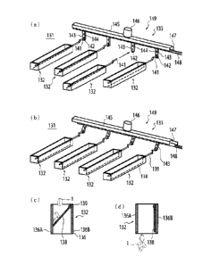
Figs. la and lb are each a plan view, Fig. lc is a front
view, and Fig. ld is a right side view, showing the overall
21
CA 02823266 2013-06-25
structure of a tablet dispensing apparatus according to a first
embodiment of the present invention.
Figs. 2a and 2b are each a plan view of an essential portion
of the tablet dispensing apparatus according to the first
embodiment.
Fig. 3a is a perspective view of a medicine guide assembly
and a temporary storage structure as seen from the right and
obliquely above, and Fig. 3b is a perspective view of a second
split guide member of the medicine guide assembly and the
temporary storage structure as seen from the left and obliquely
above.
Fig. 4 is a schematic view showing the internal structure
of the tablet dispensing apparatus.
Fig. 5a is a perspective view of a frame member of the
temporary storage structure, Fig. 5b is a perspective view of an
open-close mechanism, and Figs. 5c and 5d are each a perspective
view of the temporary storage structure.
Figs. 6a and 6b are each a perspective view of a temporary
storage device, and Figs. 6c and 6d are each a vertical
cross-sectional view of the temporary storage structure.
Figs. 7a and 7b are each a plan view showing the structure
of an essential portion of a tablet dispensing apparatus according
to a second embodiment of the present invention, Fig. 7c is a
perspective view of a medicine guide assembly and a temporary
storage structure as seen from the right and obliquely above, and
Fig. 7d is a perspective view of a second split guide member and
a second split storage member as seen from the left and obliquely
22
CA 02823266 2013-06-25
above.
Figs. 8a and 8b are a front view and a right side view,
respectively, of a tablet dispensing apparatus according to a
third embodiment of the present invention.
Fig. 9 is a side view of a tablet dispensing apparatus
according to a fourth embodiment.
Fig. 10a is a perspective view showing the appearance of
a tablet dispensing apparatus according to the related art as seen
from the left front, Fig. 10b is a schematic view showing the
internal structure of the tablet dispensing apparatus according
to the related art, Fig. 10c is a perspective view showing the
appearance of the tablet dispensing apparatus according to the
related art as seen from the left front, and Fig. 10d is a left
side view of a tablet dispensing apparatus with a manual tablet
dispenser according to the related art.
Fig. ha is a perspective view showing the appearance of
a tablet dispensing apparatus which is disclosed in an unpublished
patent application filed by the applicant and in which a temporary
storage mechanism is drawable, showing the structure of the tablet
dispensing apparatus as seen from the left front, Fig. lib is a
schematic view showing the internal structure of the tablet
dispensing apparatus, and Fig. 11c is a perspective view showing
the appearance of the tablet dispensing apparatus as seen from
the left front.
DESCRIPTION OF EMBODIMENTS
[0033]
A medicine dispensing apparatus according to an embodiment
23
CA 02823266 2013-06-25
of the present invention will be described in detail below.
[0034]
Figs. 1 to 6 show the configuration of a medicine dispensing
apparatus according to a first embodiment of the present invention.
In Figs. 1 to 3, for the sake of clarity etc., fasteners such as
bolts, couplers such as hinges, driving sources such as electric
motors, power transmission members such as timing belts, electric
circuits such as motor drivers, and electronic circuits such as
controllers are not shown in detail, and members necessary for
or related to description of the present invention are mainly
shown.
[0035]
In Figs. 1 to 6, component parts similar to those of the
medicine dispensing apparatus 10 according to the related art
shown in Fig. 10 and the medicine dispensing apparatus 30 proposed
by the applicant shown in Fig. 11 are denoted by reference numerals
obtained by adding 100 to the reference numerals affixed to their
counterparts in Figs. 10 and 11. The medicine dispensing
apparatus according to the embodiment is a tablet dispensing
apparatus 110 which is a typical example of the medicine
dispensing apparatus. Figs. la and lb are each a plan view, Fig.
lc is a front view, and Fig. id is a right side view, of the tablet
dispensing apparatus 110 according to the embodiment. Fig. 2a
is a plan view of a plurality of medicine guide assemblies 114
etc. with all medicine feeder storing units 112 pushed into a
housing 110A indicated by the broken line. Fig. 2b is a plan view
of the medicine guide assemblies 114 etc. with some of the medicine
24
CA 02823266 2013-06-25
feeder storing units 112 drawn forward out of a medicine storage
111. Fig. 3a is a perspective view of an assembly including a
medicine guide assembly 114 constituted from first and second
split guide members 114A and 1143 and a temporary storage
structure 132 as seen from the right and obliquely above. Fig.
3b is a perspective view of the second split guide member 114B
including the temporary storage structure 132 as seen from the
left and obliquely above. Fig. 4 is a schematic view showing the
internal structure of the tablet dispensing apparatus 110.
[0036]
The tablet dispensing apparatus 110 includes eight medicine
feeder storing units 112, four medicine guide assemblies 114, one
medicine collecting assembly 115, one packing device 117, a
controller 118, and an operation panel 119. The medicine feeder
storing units 112 each include a medicine feeder storing case 112A,
and a plurality of medicine feeders 113 housed in the medicine
feeder storing case 112A. The plurality of medicine feeders 113
store various types of medicines such as tablets such as pills
and capsules separately according to their types. The controller
118 outputs a control command to the plurality of medicine feeders
113 and the packing device 117.
[0037]
The medicine storage 111 includes the eight individually
slidable medicine feeder storing units 112 disposed side by side
with each other.
[0038]
In the embodiment, the four medicine guide assemblies 114
CA 02823266 2013-06-25
are each disposed between a pair of adjacent medicine feeder
storing units 112 among the eight medicine feeder storing units
112. The medicine guide assembly 114 guides the medicines
discharged from the plurality of medicine feeders 113 included
in the pair of medicine feeder storing units 112 to an exit port
located therebelow. The medicine guide assemblies 114 are each
constituted from first and second split guide members 114A and
114B that are combined with each other when the pair of medicine
feeder storing units 112 are housed in the housing 110A and that
are separated from each other when one of the pair of medicine
feeder storing units 112 is drawn out of the housing 110A. The
housing 110A has open-close doors, which are opened when the
medicine feeder storing units 112 are to be drawn out of the housing
110A. The first split guide member 114A is fixed to the medicine
feeder storing case 112A of one of the pair of medicine feeder
storing units 112. The second split guide member 114B including
the temporary storage structure 132 is fixed to the medicine
feeder storing case 112A of the other of the pair of medicine feeder
storing units 112.
[0039]
As shown in Fig. 3a, the first split guide member 114A has
the shape of a plate formed with a plurality of through holes H
configured to allow passage of the medicines discharged from
medicine discharge ports of the plurality of medicine feeders 113
included in the one of the medicine feeder storing units 112. The
second split guide member 114B includes a plate-like portion 1143a,
a first sidewall portion 114Bb, and a second sidewall portion
26
CA 02823266 2013-06-25
114Bc. The plate-like portion 114Ba is formed with a plurality
of through holes H configured to allow passage of the medicines
discharged from the plurality of medicine feeders 113 included
in the other of the medicine feeder storing units 112. The first
sidewall portion 114Bb extends along a first edge portion of the
plate-like portion 114Ba, which is located in a drawing direction
in which the medicine feeder storing unit is drawn, and extends
in a direction away from the plate-like portion 1143a. The second
sidewall portion 114Bc extends along a second edge portion of the
plate-like portion 114Ba, which is located in the direction
opposite to the drawing direction, and extends in a direction away
from the plate-like portion 1143a. In order to increase the
alignment tolerance, the width of the plate-shaped first split
guide member 114A is slightly larger than that of the plate-like
portion 1143a of the second split guide member 1143. In the
embodiment, the entirety of the temporary storage structure 132
to be described in detail later is fixed to the plate-like portion
114Ba. Thus, when the other of the pair of medicine feeder storing
units 112 is drawn out, the second split guide member 1143 and
the temporary storage structure 132 are drawn out together.
[ 0040]
The medicine guide assembly 114 constituted from the first
and second split guide members 114A and 114B provided opposite
to each other is open in its upper and lower ends. The medicine
guide assembly 114 guides a fall of all the medicines discharged
from a large number of medicine feeders 113 mounted to the
corresponding pair of adjacent medicine feeder storing units 112.
27
CA 02823266 2013-06-25
The lower end portion of the medicine guide assembly 114 is tapered
to be slightly narrow at its lower-end opening so that the
front-rear dimension of the upper opening of the temporary storage
structure 132 can be reduced.
[0041]
If the medicine guide assembly constituted from the first
and second split guide members 114A and 114B is provided for the
pair of medicine feeder storing units, the number of the medicine
guide assemblies 114 can be reduced to half the number of the
medicine feeder storing units 112. Thus, the product can be made
compact compared to that according to the related art. Adopting
such a configuration allows the medicine feeder storing unit 112
to be drawn out of the housing 110A with the inside of the first
or second split guide member 114A or 114B exposed. Therefore,
the inside of the first and second split guide member 114A and
114B can be individually cleaned, which makes it possible to clean
the medicine guide assembly 114 without putting an excessive
burden on the worker.
[0042]
In the embodiment, the four temporary storage structures
132 are respectively disposed below the four medicine guide
assemblies 114 to temporarily store the medicines dropped from
the four medicine guide assemblies 114. The four temporary
storage structures 132 are driven by a simultaneous driving
mechanism 133 configured to actuate the plurality of temporary
storage structures 132 at the same time to release the tablets
at a time. A temporary storage device 131 is constituted from
28
CA 02823266 2013-06-25
the four temporary storage structures 132 and the simultaneous
driving mechanism 133.
[0043]
As discussed earlier, the temporary storage structures 132
each include a storage portion 134 and an open-close mechanism
135, the storage portion 134 being configured to temporarily store
the medicines dropped from the medicine guide assemblies 114, the
open-close mechanism 135 being configured to bring the storage
portion 134 into a storage enabling state upon application of a
closing drive force and to bring the storage portion 134 into a
releasing state to discharge the medicines from the storage
portion 134 upon application of an opening drive force, and the
temporary storage structures 132 being each provided such that
the entire temporary storage structure 132 is drawable out of the
housing 110A as described in detail later. The simultaneous
driving mechanism 133 applies a closing drive force or an opening
drive force to the open-close mechanisms 135 of the four temporary
storage structures 132 at the same time. Coupling structures are
provided to couple the simultaneous driving mechanism 133 and the
open-close mechanisms 135 of the four temporary storage
structures 132, and each configured to release the coupling when
the entire temporary storage structure 132 is drawn out of the
housing 110A, and to establish the coupling when the entire
temporary storage structure 132 is pushed into the housing 110A.
The specific configuration of the coupling structures will be
described later.
[0044]
29
CA 02823266 2013-06-25
As shown in Fig. 5, the temporary storage structure 132 used
in the embodiment is structured by combining an elongated
rectangular tubular member or an elongated frame member 136 having
an upper-end opening portion and a lower-end opening portion (to
form the storage portion 134) , and the open-close mechanism 135.
The frame member 136 (see Fig. 5a) includes a left sidewall portion
136A and a right side plate 136B that are thin and long in the
front-rear direction, and a front plate 136C and a rear plate 136D
formed with a through hole 137 provided in the upper right corner
thereof. The hollow internal space serves as the tablet falling
path. The open-close mechanism 135 (see Fig. 5b) includes a
shutter plate 138, a rotating shaft 139, an arm 140, and a coupling
shaft 141. The shutter plate 138 is flat, and thin and long in
the front-rear direction. The rotating shaft 139 is thin and long,
and the upper side of the shutter plate 138 is coupled and fixed
to the rotating shaft 139. Both ends of the rotating shaft 139
are rotatably supported onto the frame member 136 (storage portion
134) . The arm 140 has one end fixed to the rotating shaft 139,
and is rotatable about the rotating shaft 139 over a predetermined
angular range. The coupling shaft 141 is fixed to the other end
of the arm 140, and extends in parallel with the rotating shaft
139. The rotating shaft 139 penetrates the through holes 137.
A driven link is constituted from the rotating shaft 139, the arm
140, and the coupling shaft 141. Appropriate retainers are fixed
to the rotating shaft 139.
[0045]
As shown in detail in Fig. 6, the simultaneous driving
CA 02823266 2013-06-25
mechanism 133 can actuate the four temporary storage structures
132 at the same time to release the tablets at a time. The coupling
structures configured to couple the simultaneous driving
mechanism 133 and the four temporary storage structures 132
removably couple the temporary storage structures 132 to the
simultaneous driving mechanism 133. Therefore, the coupling
structures allow individual removal of the temporary storage
structures 132, and enable open-close operation of the temporary
storage structures 132 connected thereto. As shown in Figs. 6a
and 6b, the simultaneous driving mechanism 133 includes a guide
145, an electric rotary motor 146, a slider 147, a bias spring
148, and a motion conversion mechanism (not shown) . The guide
145 is fixed, and extends in the left-right direction. The
electric rotary motor 146 is mounted to the guide 145. The slider
147 extends in the left-right direction as with the guide 145,
and is guided by the guide 145 to be able to make reciprocal motion
in the left-right direction. The bias spring 148 biases the
slider 147 leftward. The motion conversion mechanism is disposed
between the guide 145 and the slider 147 to convert rotation of
the electric rotary motor 146 into linear motion of the slider
147. When the electric rotary motor 146 is not actuated or driven,
the motion conversion mechanism (not shown) becomes free, and is
returned to the original state by the biasing force of the bias
spring 148.
[0046]
Thus, when the electric rotary motor 146 is not actuated,
the slider 147 is moved to the leftmost position within its movable
31
CA 02823266 2013-06-25
range by the biasing force of the bias spring 148 (see Fig. 6a).
When the electric rotary motor 146 is actuated, the slider 147
makes linear motion to be moved rightward within its movable range
(see Fig. 6b). After that, when operation of the electric rotary
position within its movable range by the biasing force of the bias
spring 148. A reciprocal linear motion mechanism 149 is
constituted from such a structure.
[0047]
The slider 147 of the reciprocal linear motion mechanism
149 is provided with a number of driving links 143, the number
being the same as that of the temporary storage structures 132.
The four driving links 143 are disposed side by side in the
left-right direction at the same pitch as that of the temporary
or swingably fixed to fulcrums 144 respectively (or rotatable
within a predetermined angular range). For example, the upper
end portion of each of the driving links 143 is rotatably coupled
to the slider 147 with a rotating structure (not shown).
An elongated fitting hole 142 is formed in a swing portion
of the driving link 143, that is, the lower end portion of the
driving link 143 which is opposite to the slider 147. The width
of the fitting hole 142 is slightly larger than the shaft diameter
Therefore, if the temporary storage structure 132 is pushed into
the housing, the coupling shaft 141 is inserted into the fitting
32
CA 02823266 2013-06-25
hole 142 so that the coupling shaft 141 and the fitting hole 142
are fitted with each other. If the temporary storage structure
132 is drawn forward out of the housing 110A, the coupling shaft
141 is extracted from the fitting hole 142 so that the coupling
shaft 141 and the fitting hole 142 are removed from each other.
Thus, the driving link 143 serves as a driving-side transmission
member, and the coupling shaft 141 serves as a driven-side
transmission member. The two transmission members form a
transmission mechanism provided at the coupling portion between
the simultaneous driving mechanism 133 and the temporary storage
structure 132 to releasably establish engagement therebetween.
[0049]
When the electric rotary motor 146 is not actuated, as shown
in Fig. 6c, the rotating shaft 139 of the temporary storage
structure 132 is rotated in one direction over a predetermined
angular range to bring the distal end of the shutter plate 138
into proximity to the sidewall portion 136A of the frame member
136, which brings the storage portion 134 formed above the shutter
plate into the storage enabling state. When the electric rotary
motor 146 is actuated, as shown in Fig. 6d, the rotating shaft
139 is rotated in the other direction over a predetermined angular
range to bring the shutter plate 138 closer to the sidewall portion
1363, which brings the storage portion 134 into the releasing
state.
[0050]
The medicine collecting assembly 115 is disposed in the
housing below the four temporary storage structures 132 to collect
33
CA 02823266 2013-06-25
the medicines 1 dropped from the four temporary storage structures
132. The packing device 117 is provided in the housing 110A below
the medicine collecting assembly 115 to separately pack the
medicines discharged from the medicine collecting assembly 115.
The simultaneous driving mechanism 133 of the temporary
storage device 131 does not have a tablet falling path surrounding
surface. Thus, it is sufficient to clean the temporary storage
structures 132 in regular cleaning work for the temporary storage
device 131, with the exception of maintenance work such as
disassembly and repair.
[0051]
In a steady state such as during dispensing (see Figs. 1
and 4), all the medicine feeder storing units 112 are pushed into
the medicine storage 111 to be housed in the housing. Any of the
medicine guide assemblies 114 can guide the falling tablets from
the upper-end opening to the lower-end opening with the first
split guide member 114A and the second split guide member 114B
provided close and opposite to each other and with their inner
opposite surfaces surrounding the tablet falling path. In
addition, any of the temporary storage structures 132 surrounds
the tablet falling path at the lower end portion of the
corresponding medicine guide assembly 114. The simultaneous
driving mechanism 133 drives the shutter plates 138 of the
open-close mechanisms 135 to open and close the tablet falling
path. In a closed state, the medicines (tablets) 1 discretely
dropped can be temporarily stored (see Fig. 6c). When opened,
the stored tablets can be released at a time (see Fig. 6d).
34
CA 02823266 2013-06-25
[0052]
When cleaning the medicine guide assembly 114 and the
temporary storage structure 132, the automatic dispensing
operation discussed already is stopped, and the first split guide
member 114A of the medicine guide assembly 114 and the second split
guide member 114B of the medicine guide assembly 114 and the
temporary storage structure 132 are separately cleaned. More
particularly (see Fig. 2) , first, only one of a pair of adjacent
medicine feeder storing units 112 is drawn forward out of the
medicine storage 111. If the left one of the pair of adjacent
medicine feeder storing units 112 is drawn out, the first split
guide member 114A forming the medicine guide assembly 114 is moved
out of the housing 110A, and the entire tablet falling path
surrounding surface of the first split guide member 114A is
exposed to be cleaned by wiping or the like.
[0053]
After that, the cleaned medicine feeder storing unit 112
is pushed back into the medicine storage 111, and the right one
of the pair of adjacent medicine feeder storing units 112 is drawn
forward out of the medicine storage 111. Then, the second split
guide member 114B of the medicine guide assembly 114 and temporary
storage structure 132 attached thereto are moved out of the
housing 110A to expose the entire tablet falling path surrounding
surfaces formed by the second split guide member 1143 and the
temporary storage structure 132. After the tablet falling path
surrounding surfaces are cleaned by wiping or the like, the
cleaned medicine feeder storing unit 112 pushed back into the
CA 02823266 2013-06-25
medicine storage 111. In this way, all the tablet falling path
surrounding surfaces of the medicine guide assembly 114 and the
temporary storage structure 132 can be cleaned. In addition, the
tablet falling path surrounding surfaces can be comfortably
cleaned one by one in a standing posture as if wiping a window
from inside.
[0054]
Fig. 7 illustrates an essential portion of a tablet
dispensing apparatus 210 according to a second embodiment of the
present invention. Component parts similar to those in the first
embodiment shown in Figs. 1 to 6 are denoted by reference numerals
obtained by adding 100 to the reference numerals affixed to their
counterparts in Figs. 1 to 6 to omit descriptions. Fig. 7a is
a plan view of medicine guide assemblies 214 etc. with all medicine
feeder storing units 212 pushed into a housing 210A. Fig. 7b is
a plan view of the medicine guide assemblies 214 etc. with some
of the medicine feeder storing units 212 drawn forward out of the
housing 210A. Fig. 7c is a perspective view of a medicine guide
assembly 214 constituted from a first split guide member 214A and
a second split guide member 214B and a temporary storage structure
232 constituted from a first split storage member 232A and a second
split storage member 232B as seen from the right and obliquely
above. Fig. 7d is a perspective view of an assembly constituted
from the second split guide member 214B of the medicine guide
assembly 214 and the second split storage member 2323 of the
temporary storage structure 232 as seen from the left and
obliquely above.
36
CA 02823266 2013-06-25
[0055]
The tablet dispensing apparatus 210 is different from the
tablet dispensing apparatus 110 according to the first embodiment
discussed above in that the integral temporary storage structure
132 is replaced with the first split storage member 232A and the
second split storage member 2323. That is, the temporary storage
structures 232 are each constituted from first and second split
storage members 232A and 2323 that are combined with each other
when the pair of adjacent medicine feeder storing units 212 are
housed in the housing 210A and that are separated from each other
when one of the pair of medicine feeder storing units 212 is drawn
out of the housing 210A. The first split storage member 232A of
the temporary storage structure 232 is integrally coupled to the
first split guide member 214A of the medicine guide assembly 214.
The second split storage member 232B of the temporary storage
structure 232 serves as a portion including an open-close
mechanism 235, and is coupled to the second split guide member
214B of the medicine guide assembly 214. The first split storage
member 232A has the shape of a plate integrally formed with the
first split guide member 214A. The second split storage member
232B includes an extended plate-like portion 232Ba, a first
extended sidewall portion 2323b, and a second extended sidewall
portion 2328c. The extended plate-like portion 2323a is
integrally formed with a plate-like portion 214Ba of the second
split guide member 214B. The first extended sidewall portion
232Bb extends along a first edge portion of the extended
plate-like portion 2323a, which is located in a drawing direction
37
CA 02823266 2013-06-25
in which the medicine feeder storing unit 212 is drawn, and extends
in a direction away from the extended plate-like portion 232Ba
to be continuous with a first sidewall portion 214Bb of the second
split guide member 214B. The second extended sidewall portion
232Bc extends along a second edge portion of the extended
plate-like portion 232Ba, which is located in the direction
opposite to the drawing direction, and extends in a direction away
from the extended plate-like portion 232Ba to be continuous with
a second sidewall portion 214Bc of the second split guide member
214B.
[0056]
Although not shown, the second split storage member 232B
is provided with means for restricting the swing range of a shutter
plate 238 to prevent the shutter plate 238 from moving out beyond
the first and second extended sidewall portions 232Bb and 232Bc
even if the second split storage member 232B is separated from
the first split storage member 232A.
[0057]
In this case, if only one of the two adjacent medicine feeder
storing units 212 is drawn forward out of the housing 210A, one
of the first split guide member 214A and the second split guide
member 214B of the medicine guide assembly 214 is moved out of
the housing 210A, and in accompaniment thereto, one of the first
split storage member 232A combined with the first split guide
member 214A and the second split storage member 232B combined with
the second split guide member 214B is also moved out of the housing
210A. Thus, the tablet falling path surrounding surfaces of the
38
CA 02823266 2013-06-25
first split guide member 214A and the first split storage member
232A, and the tablet falling path surrounding surfaces of the
second split guide member 2143 and the second split storage member
232B, can be cleaned by wiping or the like at the same time. The
cleaning work can be performed in a standing posture as
comfortably as wiping of a window from inside, thereby allowing
the wiping or the like to be performed easily and immediately with
the worker facing the surface to be cleaned.
[0058]
Figs. 8a and 8b are a front view and a right side view,
respectively, of a tablet dispensing apparatus 310 according to
a third embodiment of the present invention. In Fig. 8, reference
numerals obtained by adding 200 to the reference numerals used
in the first embodiment shown in Figs. 1 to 6 are used to omit
descriptions. The tablet dispensing apparatus 310 according to
the embodiment includes two air purifying devices 351 provided
at the top plate portion of a housing 310A. The air purifying
devices 351 purify air taken from outside of the housing 310A to
supply the purified air into the housing 310A. An air supply
chamber 352 is provided below the top plate portion of the housing
310A between the air purifying devices 351 and a medicine storage
311 to temporarily store purified air 353 discharged from the air
purifying devices 351. The air purifying devices 351 are each
a commercially available clean air supply unit obtained by
combining a fan configured to blow an appropriate amount of air
and a purifying member such as a HEPA filter or an ULPA filter.
The air purifying devices 351 used in the embodiment take in air
39
CA 02823266 2013-06-25
from a space above the housing 310A, purify the air to meet Class
1000 standards, for example, and feed the purified air into the
air supply chamber 352 provided immediately therebelow. The air
supply chamber 352 may temporarily store the purified air to
mitigate fluctuations in air flow or air pressure, and may be
formed from a simple box member.
[0059]
Four medicine guide assemblies 314 communicate with the air
supply chamber 352. The purified air supplied by the air
purifying devices 351 into the housing 310A flows from top to
bottom inside the medicine guide assemblies 314. Thus, the
internal spaces of the four medicine guide assemblies 314 each
form a purified air passage 354A to allow passage of at least a
part (353A) of the purified air 353. Providing the thus
configured purified air passage 354A allows the purified air 353
fed into the medicine guide assembly 314 from above to flow from
top to bottom along the medicine falling path to be further fed
into a medicine collecting assembly 315. As a result, the inside
of the medicine guide assemblies 314 and the inside of the medicine
collecting assembly 315 can be cleaned to some degree by the flow
of the purified air.
[0060]
The purified air having passed through the medicine guide
assemblies 314 and the medicine collecting assembly 315 enters
a packing device 317 together with the medicines while reducing
its flow rate. However, the purified air is not enough to be used
to clean the inside of the packing device 317. Thus, in the
CA 02823266 2013-06-25
embodiment, a purified air branch passage 354B is provided to
branch the purified air supplied from the air purifying devices
351 to allow a part (353B) of the branched purified air to directly
flow to the surroundings of or into the packing device without
passing through the purified air passage 354A. Specifically, as
shown in Fig. 8b, the purified air branch passage 354B is formed
by providing one or several air supply pipes each formed from a
vertically placed duct on the back side in the housing 310A to
communicate between the air supply chamber 352 and a lower space
in the housing 310A in which the packing device 317 is disposed.
Providing the purified air branch passage 354B allows the part
(353B) of the purified air to be guided from the air supply chamber
352 to the lower space in the housing 310A, while bypassing the
medicine guide assemblies 314, medicine feeder storing units 312,
and the medicine collecting assembly 315, to be blown toward a
medicine entry port 316 of the packing device 317. Providing the
thus configured purified air branch passage 354B allows the
packing device 317 to be reliably cleaned with the purified air.
Although the purified air branch passage 354B formed from one or
more air supply pipes is longer than the purified air passage 354A,
the purified air branch passage 354B can be formed from a pipe
such as a flexible hose, and thus can be conveniently implemented.
[00611
The air purifying devices 351 may be installed at any
location if high-performance filters are used. If the air
purifying devices 351 are disposed above the medicine feeder
storing units 312 as in the embodiment, the air purifying devices
41
CA 02823266 2013-06-25
351 take in outside air at a location remote from the floor surface.
Therefore, relatively uncontaminated air is taken into the air
purifying devices 351.
[0062]
One or more air contamination detectors are preferably
disposed in the housing 310A to detect contamination of the
purified air. Providing the air contamination detectors makes
it possible to detect that the purified air in the housing 310A
has been contaminated for some reason, and to take immediate
measures against such contamination of the purified air. The
contamination detectors may have any structure as long as the
detectors detect contamination of air at their respective
locations of installation. Examples of the contamination
detector include an optical particle sensor, which is easy to use
and inexpensive.
[0063]
The one or more air contamination detectors maybe disposed
at any location on a flow passage that allows passage of the
purified air supplied from the air purifying devices 351.
Specifically, the air contamination detectors are preferably
disposed at least one of: inside and outside of the purified air
passages 354A, inside and in the vicinity of the exit port of the
purified air branch passage 354B, inside and in the vicinity of
the medicine collecting assembly 315, inside and in the vicinity
of the packing device 317, and in the vicinity of the medicine
entry port 316.
[0064]
42
CA 02823266 2013-06-25
The results of detection by the air contamination detectors
may be utilized in anyway. For example, if the air contamination
detectors detect contamination of the purified air, a controller
serving as a control device for the air purifying devices 351 may
vary the amount of air supplied by the air purifying devices 351
according to the degree of the detected contamination.
[0065]
If the air contamination detectors detect that the purified
air is contaminated to a prescribed level (degree) or more, an
alarm signal generating device may generate an alarm signal.
[0066]
While the present invention is applied to a tablet
dispensing apparatus with no manual medicine dispenser in the
embodiment of Fig. 8, it is a matter of course that the present
invention may also be applied to a tablet dispensing apparatus
420 with a manual medicine dispenser as in a fourth embodiment
shown in Fig. 9. In the embodiment shown in Fig. 9, component
parts similar to those of the tablet dispensing apparatus with
a manual medicine dispenser according to the related art shown
in Fig. 8 are denoted by reference numerals obtained by adding
100 to the reference numerals affixed to their counterparts in
Fig. 8. Also in the embodiment, as in the third embodiment, an
air purifying device 451 is mounted on top of a housing 410A. A
manual medicine dispenser (421, 422) includes a preliminary
dispersing portion 421 of a cassette type and an operating portion
422 of a conveyor type. A large number of sectioned chambers are
formed in the preliminary dispersing portion 421 in a vertical
43
CA 02823266 2013-06-25
and horizontal arrangement. The upper side of each sectioned
chamber is open to allow input of the medicines. The lower surface
or the bottom surface of each sectioned chamber is formed from
a shutter or the like to open and close to allow discharge of the
medicines. The preliminary dispersing portion 421 can be drawn
out of the housing of the tablet dispensing apparatus 420 to allow
manually dispersion of the medicines into the sectioned chambers.
While the medicines are manually put into the preliminary
dispersing portion 421, the operating portion 422 automatically
discharges the medicines. The operating portion 422 is configured
to receive the medicines discharged from the sectioned chambers
of the preliminary dispersing portion 421, and to feed the
received medicines into a packing device 417 via a medicine
collecting assembly 415, by an amount corresponding to one
sectioned chamber at a time. When the manual medicine dispenser
of the tablet dispensing apparatus 420 is not used, the tablet
dispensing apparatus 420 operates as in the third embodiment with
the manual medicine dispenser (421, 422) drawn out. When the
manual medicine dispenser (421, 422) is used, supply of the
medicines from the medicine feeders is stopped. It should be
noted that the air purifying device 451 is in operation. As a
result, the purified air flows from the air purifying device 451
into the housing 410A at all times to continue cleaning with the
purified air.
[0067]
[Other Embodiments]
A further modification is preferably made such that the
44
CA 02823266 2013-06-25
coupling shaft 141 is smoothly inserted into the fitting hole 142
when the temporary storage structure 132 which has been disengaged
from the simultaneous driving mechanism 133 becomes engaged
therewith, although not shown or described in the embodiments
described above. For example, the distal end of the coupling
shaft 141 may be subjected to a tapering process or the like to
be tapered. Biasing means such as a weak spring, for example,
may be provided to force the temporary storage structure 132
closed in the absence of an external force to keep the coupling
shaft 141 suitable for engagement. Means for restricting a
movable range or a stop position may be individually provided for
each of the driving links 143 and the coupling shafts 141 to allow
individual adjustment of the range or the position.
[0068]
Although the manual tablet dispenser (421, 422) is disposed
below the temporary storage structures in the fourth embodiment
described above, the manual tablet dispenser (421, 422) may be
disposed above the temporary storage structures. For example,
the lowermost tablet feeder may be replaced with the manual tablet
dispenser (421, 422) in a certain medicine feeder storing unit.
Then, the manual tablet dispenser 421+422 is located above the
temporary storage structures, and drawn together with the
medicine feeder storing unit. This facilitates cleaning, repair,
etc. of the manual tablet dispenser (421, 422).
INDUSTRIAL APPLICABILITY
[0069]
According to the present invention, the simultaneous
CA 02823266 2013-06-25
driving mechanism and the plurality of temporary storage
structures can be removably coupled to each other. Therefore,
the temporary storage structures can be drawn out one by one, and
cleaning work can be performed with only the subject of the
cleaning work drawn out of the housing and with the other temporary
storage structures pushed into the housing. Therefore, the
cleaning work can be performed in a comfortable posture, and
re-adhesion of removed substances to the other temporary storage
structures can be prevented.
[0070]
The air purifying devices are provided to take in air from
outside of the housing to supply the purified air into the housing,
and the purified air passage is provided inside the medicine guide
assemblies to allow a flow of at least a part of the purified air
from top to bottom. Then, the purified air fed from above into
the medicine guide assemblies flows along the medicine falling
path from top to bottom, and is further fed into the medicine
collecting assembly. Thus, the inside of the medicine guide
assemblies and the inside of the medicine collecting assembly can
be cleaned to some degree by the flow of the purified air. Thus,
the cleaning cycle of the inside of the medicine guide assemblies
can be made longer than that according to the related art. The
purified air passing through the inside of the medicine guide
assemblies also serves to increase the falling speed of the
medicines, thereby increasing the dispensing cycle.
SIGN LISTING
[0071]
46
CA 02823266 2013-06-25
1 medicine
medicine dispensing apparatus
12 medicine feeder storing unit
30 medicine dispensing apparatus
5 42 air supply chamber
110 tablet dispensing apparatus
110A housing
111 medicine storage
112 medicine feeder storing unit
10 112A medicine feeder storing case
113 medicine feeder
114 medicine guide assembly
114A first split guide member
114B second split guide member
115 medicine collecting assembly
117 packing device
118 controller
119 operation panel
131 temporary storage device
132 temporary storage structure
133 simultaneous driving mechanism
134 storage portion
135 open-close mechanism
136 frame member
138 shutter plate
139 rotating shaft
140 arm
47
CA 02823266 2013-06-25
141 coupling shaft
143 driving link
144 fulcrum
145 guide
146 electric rotary motor
147 slider
148 bias spring
149 reciprocal linear motion mechanism
48