Note: Descriptions are shown in the official language in which they were submitted.
PUMP ENGINE WITH METERING SYSTEM FOR
DISPENSING LIQUID MEDICATION
[0001]
FIELD OF THE INVENTION
[0002] The present invention relates generally to a fail-safe
metering system for a
pump engine or fluid driver that provides improved dosing accuracy for insulin
and other
liquid medications.
BACKGROUND OF THE INVENTION
[0003] Diabetes is a group of diseases marked by high levels of blood
glucose
resulting from defects in insulin production, insulin action, or both.
Diabetes can lead to
serious health complications and premature death, but there are well-known
products
1
CA 2823345 2019-12-13
CA 02823345 2013-08-12
available for people with diabetes to help control the disease and lower the
risk of
complications.
[0004] Treatment options for people with diabetes include specialized
diets, oral
medications and/or insulin therapy. The primary goal for diabetes treatment is
to control
the patient's blood glucose (sugar) level in order to increase the chances of
a complication-
free life. It is not always easy, however, to achieve good diabetes
management, while
balancing other life demands and circumstances.
[0005] Currently, there are two principal modes of daily insulin therapy
for the
treatment of type I diabetes. The first mode includes syringes and insulin
pens that require
a needle stick at each injection, typically three to four times per day. These
devices are
simple to use and relatively low in cost. Another widely adopted and effective
method of
treatment for managing diabetes is the use of an insulin pump. Insulin pumps
can help
users keep their blood glucose levels within target ranges based on their
individual needs,
by providing continuous infusion of insulin at varying rates to more closely
mimic the
behavior of the pancreas. By using an insulin pump, users can match their
insulin therapy
to their lifestyles, rather than matching their lifestyles to how an insulin
injection is
working for them.
[0006] Conventional insulin pumps are capable of delivering rapid or short-
acting
insulin 24 hours a day through a cannula (typically a hollow metal needle or a
flexible
plastic catheter) placed under the skin. Insulin doses are typically
administered at a basal
rate and in a bolus dose. Basal insulin is delivered continuously over 24
hours, and strives
to keep one's blood glucose levels in a consistent range between meals and
overnight.
Some insulin pumps are capable of programming the basal rate of insulin to
vary according
to the different times of the day and night. Bolus doses are typically
administered when
the user consumes a meal, and generally provide a single additional insulin
injection to
balance the carbohydrates consumed. Some conventional insulin pumps enable the
user to
program the volume of the bolus dose in accordance with the size or type of
the meal
consumed. Conventional insulin pumps also enable a user to infuse a
correctional or
supplemental bolus of insulin to compensate for a low blood glucose level at
the time the
user is calculating a meal bolus.
[0007] There are many advantages of conventional insulin pumps over other
methods of diabetes treatment. Insulin pumps deliver insulin over time rather
than in
single injections and thus typically result in less variation within the blood
glucose range
2
CA 02823345 2013-08-12
that is recommended by the American Diabetes Association. Conventional insulin
pumps
may reduce the number of needle sticks which the patient must endure, and may
make
diabetes management easier and more effective for the user, to enhance the
quality of the
user's life. Typically, regardless of whether patients are on multiple direct
injections
(MDIs) or a pump, they take fasting blood glucose medication (FBGM) when they
wake,
and they also test for glucose in the blood during or after each meal to
determine whether a
correction dose is required. In addition, patients may test for glucose in the
blood prior to
sleeping to determine whether a correction dose is required, e.g. after intake
of a snack.
[0008] There are generally two types of insulin pumps: conventional pumps
and
patch pumps.
[0009] Conventional pumps require the use of a disposable component,
typically
referred to as an infusion set, tubing set or pump set, which conveys the
insulin from a
reservoir within the pump into the skin of the user. An infusion set typically
consists of a
pump connector, a length of tubing, and a hub or base from which a hollow
metal infusion
needle or flexible plastic catheter extends. The base has an adhesive that
retains the base
on the skin surface during use. The base may be applied to the skin manually
or with the
aid of a manual or automatic insertion device. Often, the insertion device is
a separate,
stand-alone unit that the user is required to carry and provide.
[0010] Another type of insulin pump is a patch pump. Unlike a conventional
infusion pump and infusion set combination, a patch pump is an integrated
device that
combines most or all of the fluidic components (including the fluid reservoir
and pumping
mechanism) in a single housing which is adhesively attached to an infusion
site, and does
not require the use of a separate infusion (tubing) set. A patch pump adheres
to the skin,
contains insulin (or other medication), and delivers the insulin over a period
of time via an
integrated subcutaneous cannula. Some patch pumps communicate with a separate
controller device wirelessly (as in one device sold by Insulet Corporation
under the brand
name OmniPod0), while others are completely self-contained. These devices
usually need
to be replaced on a frequent basis, such as every three days, when the
reservoir is
exhausted or complications may otherwise occur.
[0011] An exemplary insulin patch pump 100 is shown in FIG. I. The patch
pump
utilizes a single reservoir 110 that retains a full dose requirement for the
duration of the
pump device, which is typically 3 days. A pump engine 120 or other fluid
driver typically
applies force directly to the single reservoir 110, either through a secondary
element, such
3
CA 02823345 2013-09-13
as a plunger, or by direct deformation of the reservoir 110. This causes
insulin to flow out
of the reservoir 110 via the fluid line 112 and the cannula 111 and into the
subcutaneous
(SC) tissue of the patient.
[0012] In another type of patch pump 200, a simple form of a fluid driver
is a
preloaded spring 220, as shown in FIG. 2. In insulin patch pumps utilizing a
preloaded
spring 220, the continuous flow rate of insulin into the subcutaneous tissue
is controlled
only by a calibrated limiting orifice in the fluid line 212 or cannula 211,
and the spring
force applied to the reservoir 210 by the preloaded spring 220.
[0013] Shortcomings of this type of pump include spring force decay along
the
spring path resulting in flow rate decay, and spring force variation over the
shelf life of the
pump engine. Additionally, this type of insulin pump lacks a "fail-safe" or
means of
protecting the patient from accidentally receiving an entire reservoir volume
or delivering
the entire reservoir content.
[0014] Alternatively, in another type of patch pump 300, the flow rate of
insulin
into the subcutaneous tissue can be discontinuous by incorporating a
directional control
valve 330, such as an on/off valve, into the fluid line 312 to provide
infusion via the
cannula 311 when required, as shown in FIG. 3. However, the valve 330 when
used with a
fluid driver 320 could still fail in the open position, resulting in a single
point failure which
would allow the full dose of drug to be infused into the patient. For example,
if the valve
330 shown in FIG. 3 fails, the fluid path remains open and the pressurized
reservoir 310
will be completely infused into the patient.
[0015] FIG. 4 illustrates another patch pump 400 for the treatment of
diabetes. The
illustrated fluid driver is a pump engine or motor 420. This device is
typically a stepper
motor or other device that behaves similarly, such as a mechanism that
advances a small
incremental dose from a syringe-style reservoir 410 to the infusion site via
the fluid line
412 and the cannula 411, as shown in FIG. 4. The illustrated device provides a
superior
form of insulin therapy as compared with Multiple Daily Injections (MDIs),
which is the
prevalent method of insulin therapy for both type 1 and type 2 diabetes. The
current trend
for basal delivery in the industry is to pump smaller incremental doses over
the target
duration and thereby approach continuous infusion. Smaller incremental doses
are also
more suitable for pediatric applications.
[0016] Dosing accuracy is still a concern with the current trend of pump
engines.
Applicable standards, such as IEC 60601-2-24, require dose accuracy to be
within +/- 5%
4
CA 02823345 2013-08-12
of target, creating difficulty for conventional volumetric pumps, which push a
plunger by
extremely small linear translations, approximately 2 micrometers per step.
[0017] For injections, higher accuracy can be provided by reducing the
syringe
diameter so that the same linear translation of the syringe plunger provides a
smaller dose.
For example, the same incremental movement of the plunger in a 3/10 cc syringe
510
having an inner diameter DI of 0.338 inch, as illustrated in FIG. 5A, provides
one-eighth
the dose for the same incremental movement as compared to a 3 ml syringe 520
or eight
times the accuracy of a 3m1 syringe 520 having an inner diameter D2 of 0.110
inch, as
illustrated in FIG. 5B. The higher accuracy of the 3/10 cc syringe 510 may
eliminate or
reduce dosing errors and enables the use of higher concentration drugs, such
as U200 and
U500 insulin, which is often prescribed for patients with type 2 diabetes.
[0018] Accordingly, there is a need for a fail-safe metering system for a
fluid driver
or pump engine that incorporates the improved dosing accuracy of a smaller
syringe
diameter and protects the patient from inadvertently receiving an overdose of
medicament.
[0019] Additionally, there is a need for a low cost metering system that
can
operated with any fluid driver or pump engine, including a completely
disposable pumping
system such as a patch pump.
SUMMARY OF THE INVENTION
[0020] An object of the present invention is to substantially address the
above and
other concerns, and provide higher levels of infusion accuracy in combination
with a fail-
safe metering system for an infusion pump that delivers insulin or other
liquid medication.
[0021] Another object of the present invention is to address the
inadvertent
overdosing of a patient by only pre-loading and pressurizing a safe or less-
than-harmful
dose of medicament in the reservoir of the metering system in the insulin
infusion pump.
[0022] Another object of the present invention is to provide a metering
system that
permits the use of higher concentration drugs while abiding by industry
requirements for
pump engine accuracy.
[0023] Another object of the present invention is to provide a metering
system that
permits fine incremental dosing to approximate continuous infusion.
CA 02823345 2013-08-12
Another object of the present invention is to provide a low-cost metering
system that can
be integrated as part of an infusion pump device with any type of fluid driver
or pump
engine, including pump engines with low or poor accuracy.
BRIEF DESCRIPTION OF THE DRAWINGS
[00241 The various objects, advantages and novel features of the exemplary
embodiments of the present invention will be more readily appreciated from the
following
detailed description when read in conjunction with the appended drawings, in
which:
FIG. 1 depicts an illustrative embodiment of the basic elements of an insulin
infusion patch pump;
FIG. 2 depicts an illustrative embodiment of an insulin infusion patch pump
having
a preloaded spring as the pump engine;
FIG. 3 depicts an illustrative embodiment of an insulin infusion patch pump
with a
preloaded spring pump engine and a directional control valve;
FIG. 4 depicts an illustrative embodiment of an insulin infusion patch pump
having
a stepper motor as the pump engine;
FIG. 5A depicts a cross-sectional and an end view of an illustrative
embodiment of
a 3/10 cc syringe;
FIG. 5B depicts a cross-sectional and an end view of an illustrative
embodiment of
a 3m1 syringe;
FIG. 6 depicts an illustrative embodiment of an insulin infusion metering
system of
the present invention connected to a primary pump engine;
FIG. 7 depicts an illustrative embodiment of an insulin infusion metering
system of
the present invention incorporated into a Micro Electro Mechanical Systems
(MEMS) chip;
FIG. 8 depicts an illustrative alternate embodiment of an insulin infusion
metering
system of the present invention incorporating a MEMS chip;
FIG. 9 depicts another illustrative alternate embodiment of an insulin
infusion
metering system of the present invention incorporating a MEMS chip;
FIG. 10 depicts another illustrative alternate embodiment of an insulin
infusion
metering system of the present invention incorporating a MEMS chip; and
FIG. 11 depicts another illustrative alternate embodiment of an insulin
infusion
metering system of the present invention incorporating a MEMS actuator.
6
CA 02823345 2013-08-12
[0025] Throughout the drawing figures, like reference numbers will be
understood
to refer to like elements, features and structures.
DETAILED DESCRIPTION OF THE EXEMPLARY EMBODIMENTS
[0026] Embodiments of the present invention relate to a fail-safe metering
system
for a pump engine or fluid driver that provides improved insulin dosing
accuracy for
insulin and other liquid medications.
[0027] An illustrative embodiment of the components of a fail-safe metering
pump
system 600 according to the present invention is shown in FIG. 6. Referring to
FIG. 6, the
infusion pump system generally includes a fluid driver in the form of a pump
engine 620, a
primary reservoir 610, and a metering system 630 including a secondary
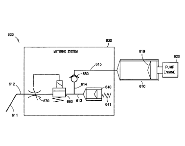
reservoir 640, at
least one check valve 650, at least one directional control valve 660, and an
adjustable flow
valve 670. In another embodiment described herein, the adjustable flow valve
670 is
replaced by a calibrated limiting orifice. In yet another embodiment, the
check valve(s)
650 is replaced by the directional control valve(s) 670. Fluid lines 612, 613,
614 and 615
connect the various components of the system, as illustrated in FIG. 6.
[0028] The pump engine 620 of the illustrative embodiments of the present
invention is interchangeable. The pump engine 620 may be a spring-driven pump,
stepper
motor driven pump, an electrochemical pump, an electro-osmotic pump, or any
positive
pressure pump.
[0029] The primary reservoir 610 or macro-reservoir is a bulk fluid storage
chamber for storing and dispensing a medicament, such as insulin, and may
comprise a 3
ml syringe. The dosing accuracy of the primary reservoir's pump engine 620
could be
anywhere within +1- 10% of target dose.
[0030] The secondary reservoir 640 or micro-reservoir is provided to limit
inadvertent insulin delivery by only pre-loading and pressurizing a safe or
less-than-
harmful dose of insulin medicament within the secondary reservoir 640. A fluid
driver
641, which can be a preloaded spring, solenoid, or other type of fluid driver,
delivers
incremental micro-doses from the secondary reservoir to the infusion site.
[0031] The check valve 650 is provided to eliminate flow back to the
primary
reservoir during the secondary reservoir delivery cycle. In an exemplary
embodiment, as
7
CA 02823345 2013-08-12
exemplified in FIG. 6, the pump engine 620 applies pressure to a plunger 619
to expel
insulin from the primary reservoir 610 into the fluid line 615, opening the
check valve 650,
until the insulin has been transferred to the secondary reservoir 640.
[0032] The directional control valve 660 controls the isolation of the
fluid path
when filling or dispensing from the secondary reservoir 640. The directional
control valve
660 is electrically controlled and is normally closed to prevent unintentional
delivery of
insulin to the infusion site. Embodiments of the directional control valve 660
include, but
are not limited to, isolation valves such as gate valves, pinch valves, spool
valves or the
like.
[0033] The opening of the normally closed directional control valve 660
enables
insulin to flow to the infusion site with the flow rate controlled by the
adjustable flow
valve 670. A controller (not shown in Fig. 6) calculates the duration for
which the
directional control valve 660 remains open based on the pressure being applied
to the
insulin in the secondary reservoir 640 by the fluid driver 641 and the
opening/orifice in the
adjustable flow valve 670. That is, the controller converts the patient's dose
requirements
into flow rate and duration settings.
[0034] The operation of the fail-safe metering pump system 600 shown in
FIG. 6 is
discussed below.
[0035] When the fluid level in the secondary reservoir 640 is low, the pump
engine
620 is activated to transfer insulin from the primary reservoir 610 to the
secondary
reservoir 640. With the check valve 650 in an open position and the adjustable
flow valve
670 in a closed position, insulin is permitted to flow through fluid lines
613, 614 and 615
into the secondary reservoir 640 from the primary reservoir 610. Check valves,
such as the
check valve 650, are typically spring loaded N/C (normally closed) valves in
which a ball
is engaged into a seat in a manner that blocks downstream flow through the
orifice in the
seat. Hence, when the line pressure opposing the ball increases beyond the
rated cracking
pressure of the check valve, the ball dislodges from the seat allowing
downstream flow
through the orifice in the seat. The opening and closing of check valve 650
occurs when
the pump engine 620 moves the plunger 619, creating a positive pressure in the
fluidic line
615 that is greater than the cracking pressure in the check valve 650, and the
pressure in
fluidic line 614/613, which is generated by the fluid driver 641.
[0036] When a pump controller of the system 600 receives a signal to
provide
insulin, the directional control valve 660 opens, while the check valve 650 is
in a closed
8
CA 02823345 2013-08-12
position, to allow flow to the infusion site via the fluid line 612 and a
hollow metal needle
or flexible plastic catheter 611 with the flow rate controlled by the
adjustable flow valve
670. Embodiments of the adjustable flow valve 670 include, but are not limited
to, control
valves that modulate flow by varying the diameter of the opening by a certain
percentage,
such as diaphragm valves or the like.
[0037] In this embodiment, the line pressure, which is the pressure applied
to the
secondary reservoir 640 by the fluid driver 641, such as a preloaded spring,
is known and
the flow of insulin is regulated depending on the dose requirement for basal
or bolus. The
dose delivered is a function of the line pressure, the duration for which the
directional
control valve 660 is open, and the variable limiting orifice in the adjustable
flow valve 670.
Ambient temperature and atmospheric pressure could also be factored into the
infusion
dose calculation to further improve dose accuracy.
[0038] The dosing accuracy of the metering system 630 with the secondary
reservoir 640 of illustrative embodiments of the present invention provides
higher levels of
infusion accuracy that can be within +/- 1% of the target dose regardless of
the pump
engine chosen for the primary reservoir, while preventing the inadvertent
overdosing of a
patient by only pre-loading and pressurizing a safe or less-than-harmful dose
of
medicament in the secondary reservoir 640 of the metering system 630.
[0039] Illustrative embodiments of the metering system infusion pump device
600
of the present invention may include, but are not limited to, sensors for
detecting occlusion
or back pressure within the infusion pump device, sensors for detecting
bubbles in the
delivery line of the infusion pump device, sensors for detecting the fill
status of the
secondary reservoir 640 of the infusion pump device 600, including the end of
the
secondary reservoir 640 or insulin remaining in the secondary reservoir 640,
sensors for
detecting leakage in the infusion pump device 600, and sensors for measuring
the flow rate
of the insulin or other medications.
[0040] Referring to FIG. 7, an infusion pump system 700 in accordance with
another illustrative embodiment of the present invention combines the sensors
and
elements of the metering system 730 of the infusion pump, as in the embodiment
of FIG. 6,
such as the check valve 750, the directional control valve 760 and the
adjustable flow valve
770, into a Micro Electro Mechanical Systems (MEMS) chip 705 that is connected
to the
primary reservoir 710 and the secondary reservoir 740 via the fluid lines 713,
714 and 715.
9
CA 02823345 2013-08-12
[0041] Combining these components into a MEMS chip 705 is a low-cost and
efficient way to provide many of the metering system components and the
sensing
elements typically required in an insulin infusion pump in a smaller package,
thus reducing
the overall size of the infusion pump device.
[0042] In the infusion pump system 700, when the fluid level in the
secondary
reservoir 740 is low, the pump engine 720 is activated to transfer insulin
from the primary
reservoir 710 to the secondary reservoir 740 by moving the plunger 719 within
the
reservoir 710. With the check valve 750 in an open position and the adjustable
flow valve
770 in a closed position, insulin is forced to flow through fluid lines 713,
714 and 715 into
the secondary reservoir 740 from the primary reservoir 710. When a pump
controller of
the system 700 receives a signal to provide insulin, the directional control
valve 760 opens,
while the check valve 750 is in a closed position, to allow flow of the
insulin from the
pressurized secondary reservoir 740 to the infusion site via the fluid line
712 and into the
hollow needle or catheter 711, with the flow rate being controlled by the
adjustable flow
valve 770. The fluid driver 741 can deliver incremental micro-doses from the
secondary
reservoir 740 to the infusion site.
[0043] Infusion pump system 800 is another illustrative embodiment of the
present
invention incorporating metering system elements of an infusion pump device
into a
MEMS chip 805 and is shown in FIG. 8. Referring to FIG. 8, the fluid delivery
system
800 generally includes a pump engine 820 a primary reservoir 810, and a
metering system
830 including a secondary reservoir 840, a fluid driver 841, a flow control
valve 850, a
directional control valve 860, an adjustable flow valve 870, a pressure sensor
880, and two
position sensors 890, 891.
[0044] The pump engine 820 of illustrative embodiments of the present
invention is
interchangeable and may be a spring-driven pump, a stepper motor driven pump,
an
electrochemical pump, an electro-osmotic pump, or any positive pressure pump.
[0045] The primary reservoir 810 or macro-reservoir is a bulk fluid storage
chamber for storing and dispensing insulin or other medicament, and may
comprise a 3 ml
syringe. The dosing accuracy of pump engine 820 could vary within +/- 10% of
the target
dose.
[0046] The secondary reservoir 840 or micro-reservoir of the metering
system 830
is provided to limit inadvertent insulin delivery by only pre-loading and
pressurizing a safe
or less-than-harmful dose of insulin medicament within the secondary reservoir
840. A
CA 02823345 2013-08-12
fluid driver 841 in the form of a preloaded spring, stepper motor, or other
fluid driver
delivers incremental micro-doses from the secondary reservoir 840. One or more
position
sensors 890, 891 are connected to the secondary reservoir 840. The position
sensors 890,
891 provide feedback to the pump controller on the fill status of the
secondary reservoir
840.
[0047] The flow control valve 850 controls the insulin flow from the
primary
reservoir 810 to the secondary reservoir 840 via the fluid lines 813, 814 and
815. The flow
control valve 850 opens to fill the secondary reservoir 840 with insulin from
the primary
reservoir 810. The flow control valve 850 allows partial delivery to the
secondary
reservoir 840, which allows increased dosing accuracy and the option of a
larger secondary
reservoir 840. Moreover, by using the flow control valve 850, a simple pump
engine, such
as a spring/elastic actuator or membrane, or any constant pressurized
mechanism such as a
gas actuator, may be utilized in the fluid delivery system 800. Refilling of
the secondary
reservoir 840 occurs between the incremental dose delivery to the patient,
i.e., when insulin
is not being delivered to the patient.
[0048] The directional control valve 860 controls the isolation of the
fluid path,
between the fluid lines 812 and 813, when dispensing from the secondary
reservoir 840.
The directional control valve 860 is provided to prevent unintentional
delivery of insulin to
the infusion site by permitting the flow of insulin only when required to
satisfy the
patient's insulin requirement and only in the direction of the arrow on the
valve 860,
illustrated in FIG. 8, from fluid line 813 into fluid line 812.
[0049] The opening of the directional control valve 860 enables insulin to
flow to
the infusion site with the flow rate controlled by the adjustable flow valve
870.
[0050] The pressure sensor 880 is used for sensing and monitoring the line
pressure
and can generate a signal to the pump controller confirming that the secondary
reservoir
840 is filled in order to stop the pump engine 820 from pumping additional
insulin to the
secondary reservoir 840. The single pressure sensor 880 is used to detect
pressure decay,
and by opening the valves 850, 860 and 870 sequentially, the single sensor 880
can
determine where in the fluidic system a leak may exist, the fill state of both
the primary
reservoir 810 and the secondary reservoir 840, and whether partial or complete
occlusion
exists. Alternately, the position sensors 890, 891 can be used for this
purpose, and the
pressure sensor 880 can be utilized to determine leakage in the system.
11
CA 02823345 2013-08-12
[0051] The illustrative embodiment of the present invention in FIG. 8
combines the
sensors and elements of the metering system, such as the flow control valve
850, the
directional control valve 860, the adjustable flow valve 870 and the pressure
sensor 880,
into a Micro Electro Mechanical Systems (MEMS) chip 805 that is connected to
the
reservoirs 810 and 840.
[0052] The operation of the infusion pump system incorporating metering
system
elements into MEMS chip 805 will be discussed with continued reference to FIG.
8.
[0053] The pump engine 820, via the primary reservoir 810, is activated
temporarily by a pump controller (not shown in FIG. 8) to fill the secondary
reservoir 840
with insulin by opening the flow control valve 850 whenever the fluid level in
the
secondary reservoir 840 is low according to an electrical signal sent by the
position sensors
890, 891 connected to the secondary reservoir 840.
[0054] Once the secondary reservoir 840 is full, the filled status of the
secondary
reservoir 840 is confirmed to the pump controller by the duration of the
refill cycle, or by
feedback from the pressure sensor 880, or with an electrical signal from the
position
sensors 890, 891 connected to the secondary reservoir 840. The signal from the
position
sensor 891 is transmitted to the pump controller of the system 800 to close
the flow control
valve 850 and stop the pump engine 820 from pumping insulin from the primary
reservoir
810. Alternately, the pressure sensor 880 can generate a similar signal to
stop the pump
engine 820 from pumping insulin from the primary reservoir 810, when the
secondary
reservoir 840 is filled either independently, when the pressure sensed has
stabilized, or in
conjunction with a second pressure sensor (not shown) located in the
downstream fluidic
line 813 or 814.
[0055] The secondary reservoir 840 can be of the same size as the smallest
incremental dose requirement, e.g. 0.5 tL / 0.25 1.11_,, such that one
complete evacuation
cycle of the secondary reservoir will deliver 0.5 tL / 0.25 AL to the patient.
Due to the
small diameter of the secondary reservoir 840, when the same linear
translation of the
syringe plunger provides a smaller dose, dosing accuracy is improved to within
+/-1% of
the target dose. Additionally, due to the relatively small geometry of the
secondary
reservoir 840, a maximum dose that can be delivered from a system failure is
small, thus
providing a fail-safe that prevents the patient from receiving an overdose of
insulin. To
deliver a large dose to a patient, such as bolus, multiple incrementing doses
(equal or
smaller than the volume of the secondary reservoir 840) are required.
12
CA 02823345 2013-08-12
[0056] Incremental dosing of insulin from the secondary reservoir 840 is
facilitated
by the opening of the directional control valve 860, which enables insulin
flow from the
pressurized secondary reservoir 840 to the infusion site, via the fluid line
812 and into the
hollow needle or catheter 811. The flow rate of the insulin is controlled by
the adjustable
flow valve 870.
[0057] When complete delivery of the insulin dose from the secondary
reservoir
840 is sensed by the position sensors 890, 891, the pump controller of the
system 800
closes the directional control valve 860 and opens the flow control valve 850,
thus
repeating the cycle of filling the secondary reservoir 840 after each
individual cycle. In
addition, the presence of the pressure sensor 880 at fluid line 815 allows the
fluid delivery
system 800 to determine how much medication was filled in the primary
reservoir 810,
since the sensed pressure is proportional to the displacement or position of
the plunger 819
in the primary reservoir 810.
[0058] Consistent with the other described embodiments of the present
invention,
only one valve needs to be open at a time. For example, to transfer insulin
from the
primary reservoir 810 to the secondary reservoir 840, the flow control valve
850 is opened
and the directional control valve 860 is closed. To infuse insulin into the
patient, the flow
control valve 850 is closed and the directional control valve 860 is open. At
no time
during the duration of use of the patch pump 800 are both valves 850 and 860
simultaneously opened. In addition, it is possible to combine the functions of
the valves.
For instance, the directional control valve 660, 760, 860 can be incrementally
adjustable
such that it can achieve the function of the adjustable flow valve 670, 770,
870. In such an
embodiment, the adjustable flow valve 670, 770, 870 can be omitted.
[0059] Syringe-type reservoirs are shown in FIGS. 6-8, but the reservoirs
utilized
in the instant invention can be rigid or flexible and the configuration can
vary depending
on the pump engine selected.
[0060] Additional illustrative embodiments of the present invention
incorporating
metering system elements of an infusion pump device into a MEMS chip are shown
in
FIGS. 9 and 10. FIG. 9 illustrates a metering system for an infusion pump
device
incorporated into a MEMS chip with an energized reservoir. FIG. 10 illustrates
a metering
system for an infusion pump device incorporated into a MEMS chip with the
micro-
reservoir or secondary reservoir filled and emptied by a linear actuator.
13
CA 02823345 2013-08-12
[0061] Referring to FIG. 9, the metering system 1000 generally includes a
primary
reservoir 7, a micro-reservoir 3 with engine or driver 4, pressure sensors 2a,
2b, a
controller 8, first and second N/C (normally closed) flow control valves la
and lb, a
controlled orifice 5, and fluidic interconnects or fluid lines 14-18. FIG. 10
also shows a
pump engine 9 or other fluid driver for the primary reservoir 7.
[0062] The pump engine 9 in illustrative embodiments of the present
invention is
optional and interchangeable, and may be a spring-driven pump, a stepper motor
driven
pump, an electrochemical pump, an electro-osmotic pump, or the like.
[0063] The primary reservoir 7 is a bulk fluid chamber for storing and
dispensing
insulin medicament, and may comprise a 3 ml syringe-style reservoir. The
secondary
reservoir or micro-reservoir 3 of the metering system is provided to limit
inadvertent
insulin delivery by pre-loading and pressurizing only a safe or less-than-
harmful dose of
insulin medicament within the micro-reservoir 3. A preloaded spring 4, or
other fluid
driver delivers incremental micro-doses from the micro-reservoir 3 to the
infusion site.
[0064] One or more pressure sensors 2a, 2b are connected to the micro-
reservoir 3.
The pressure sensors 2a, 2b provide feedback to the pump controller 8 on the
fill status of
the micro-reservoir 3, detect occlusion or back pressure in the infusion pump
device, detect
leakage in the infusion device, and detect the injection flow rate of the
insulin in the
infusion pump device by measuring the pressure in the fluid lines 17 and 18.
[0065] The pump controller 8 interfaces with the pressure sensors 2a, 2b
and
actuates various components of the metering system of the present invention,
such as the
flow control valves la and lb, and can also interface with a host computer or
wireless
controller (not shown).
[0066] The first N/C flow control valve la controls the insulin flow from
the
primary reservoir 7 to the micro-reservoir 3. The first N/C flow control valve
la opens to
fill the micro-reservoir 3 with insulin from the primary reservoir 7. The
second flow
control valve lb controls the isolation of the fluid path when dispensing from
the micro-
reservoir 3 to the infusion site and prevents unintentional delivery of
insulin to the infusion
site.
[0067] The controlled orifice 5, which may comprise an adjustable flow
valve, is
provided to allow the flow rate of insulin into the subcutaneous tissue of the
patient to be
calculated.
14
CA 02823345 2013-08-12
[0068] A check valve (not shown) can be optionally provided to eliminate
flow
back to the macro-reservoir or primary reservoir 7 during the micro-reservoir
delivery
cycle. Typically, such check valve would be incorporated into the system if
the flow
control valve N/C la were not part of the system.
[0069] FIGS. 9 and 10 both illustrate metering systems 1000, 1001 that can
be
incorporated into a MEMS chip in a manner similar to the embodiments
illustrated in
FIGS. 7 and 8, wherein the combination of the flow control valve N/C la and
the micro-
reservoir 3 safeguard the infusion pump engine from inadvertent insulin
delivery by pre-
loading and pressurizing only a safe or less-than-harmful dose of insulin
medicament
within the micro-reservoir 3. A fluid driver 4 in the form of a preloaded
spring, a solenoid,
or other fluid driver delivers incremental micro-doses from the micro-
reservoir 3 to the
infusion site in order to improve the accuracy of the insulin doses delivered
to the infusion
site to within +/-1% of the target dose. Additionally, the pressure sensors
2a, 2b illustrated
in FIGS. 9 and 10 provide feedback on the fill status of the micro-reservoir
3, detect
occlusion or back pressure in the infusion pump device, detect leakage in the
infusion
device, and detect the injection flow rate of the insulin in the infusion pump
device.
[0070] FIG. 11 illustrates another embodiment of a metering system that can
be
incorporated into a MEMS chip of the present invention, wherein a MEMS
actuator is
utilized to shift the gate of a two position gate valve 11. Specifically, when
an electric
potential is applied to the plates of the gate valve 11, the central plate is
actuated and slides
with respect to the outer plates. Depending on the position of the central
plate, the gate
valve 11 will allow flow from either the primary reservoir to the secondary
reservoir or
from the secondary reservoir to the infusion site. In the absence of an
electrical potential,
however, the central plate of the gate valve 11 is aligned to allow flow from
the primary
reservoir to the secondary reservoir, as illustrated in FIG. 11. The gate
valve 11, pressure
sensors 2a, 2b, 2c, micro-reservoir 3 and engine 4 and accompanying
interconnects can be
incorporated into a custom manifold 50 or MEMS chip. Alternately, the gate
valve 11
could include a third position, such that in the absence of electrical power,
all flow is
blocked.
[0071] In an alternative embodiment of the present invention, a MEMS
actuator is
utilized to open two N/C displacement gate valves 12a and 12b, instead of the
single gate
valve 11, to allow flow independent control of the flow from the primary
reservoir 7 to the
secondary reservoir 3 and from the secondary reservoir 3 to the infusion site.
Specifically,
when an electric potential is applied to the plate of the N/C gate valve 12a,
the central plate
thereof is actuated and slides with respect to the outer plates. This causes
the N/C gate
valve 12a to align and open the flow channels from the primary reservoir 7 to
the
secondary reservoir 3. Removing the electrical power from N/C gate valve 12a
shifts the
central plate to the N/C position. To provide flow from the secondary
reservoir 3 to the
infusion site, electrical power is then applied to the central plate of the
N/C gate valve 121),
and the central plate is actuated and slides with respect to the outer plates.
This causes the
central plate of the gate valve 12b to align and open the flow channels from
the secondary
reservoir 3 to the infusion site. In the absence of an electrical potential,
however, the plates
of the two gate valves 12a and 12b are misaligned, which blocks the flow
channels and
stops flow to the infusion site.
[0072] Accordingly, illustrative embodiments of the present invention
provide
higher levels of infusion accuracy in combination with a fail-safe metering
system for an
insulin infusion pump, prevent inadvertent overdosing of a patient by pre-
loading and
pressurizing only a safe or less-than-harmful dose of medicament in the
reservoir of the
metering system in the insulin infusion pump, permit the use of higher
concentration drugs
while abiding by industry requirements for pump engine accuracy, permit fine
incremental
dosing to approximate continuous infusion, and provide a low-cost metering
system that is
interchangeable with any type of pump engine, including pump engines with low
accuracy.
[0073] The individual components used in the exemplary patch pump
embodiments
disclosed herein, including pump engines, fluidic assemblies, metering
systems, catheter
deployment assemblies, fluid reservoirs and control systems, can be based on
existing
designs and technologies which are known in the art. For example, pump
engines, fluidic
assemblies and metering systems utilizing stepper motors, shape memory alloy
(SMA)
actuators, piezoelectric actuators, Micro Electro Mechanical Systems (MEMS)
devices,
and directional control valves may be used. Fluid reservoirs may be rigid or
deformable
(e.g., with force applied by a movable plunger or preloaded spring).
[0074] The following U.S. and foreign patent documents disclose
exemplary
components and subsystems which may be used in the practice of the present
invention:
16
CA 2823345 2019-12-13
CA 02823345 2013-08-12
P-9910 (59423)
US 5,858,001 US 7,128,727
US 5,858,005 US 7,226,278
US 5,957,895 US 7,250,037
US 6,074,369 US 7,303,549
US 6,551,276 US 7,678,079
US 6,589,229 US 7,857,131
US 6,656,158 US 8,021,334
US 6,740,059 US 2008/0097381
US 6,852,104 US 2009/0048563
US 6,960,192 US 2009/0062778
US 7,052,251 EP 2019206
US 7,109,878
[0075] While certain exemplary embodiments of the present invention have
been
shown and described herein with reference to certain preferred embodiments
thereof, it will
be understood by those skilled in the art that various changes in form and
details may be
made therein without departing from the spirit and scope of the invention as
defined in the
appended claims and their equivalents.
17