Note: Descriptions are shown in the official language in which they were submitted.
CA 02823486 2013-06-28
PCT/EP 2011/074 274- 14-03-2013
2011/001 WO
1
ADAPTOR MEANS FOR USE IN COMBINATION WITH A PRE-FILLED SYRINGE
AND A SAFETY DEVICE, SAFETY DEVICE AND INJECTION DEVICE
Technical Field
The present invention generally relates to safety devices that provide needle
safety and
more particularly to safety devices for pre-filled syringes. An adaptor means
is provided
that is adapted to mount a pre-filled syringe within the safety device. The
safety device
is adapted to avoid accidental needle pricks and needle injuries before,
during and after
an injection of a medication or drug contained in the pre-filled syringe. In
particular, the
safety device provides needle safety for a subcutaneous self-administrated
injection or
for an injection administered by a health-care professional. The present
invention further
relates to injection devices comprising a pre-filled syringe.
Background of the Invention
Pre-filled syringes that are filled with a selected dosage of a medication are
well known
injection devices for administering the medication to a patient. Safety
devices for
covering a needle of a pre-filled syringe before and after use are also well
known.
Typically, these devices comprise a needle shield that is either manually
moved or
moved by the action of a relaxing spring to surround the needle.
A different type of safety device known in the state of the art achieves the
object of
providing needle safety by arranging the pre-filled syringe movable relative
to a body,
where the pre-filled syringe is retracted into the body after the injection.
= WO 2010/104779 Al discloses a pharmaceutical delivery apparatus with an
automatic
syringe retraction following a manually controlled injection. The apparatus
includes a
housing, a syringe carriage, a medication-filled syringe held within the
carriage, the
syringe needle tip being disposed within the housing in a first position and
projecting
AMENDED SHEET
CA 02823486 2013-06-28
PCT/EP 2011/074 274- 14-03-2013
2
from the housing beyond the housing proximal end for insertion into an
injection site in a
second position, a manually shif table plunger, means on the carriage and the
housing
and the plunger for causing the carriage to advance from the first position to
the second
position and for injecting medicine from the syringe when the plunger is
manually
plunged proximally toward the housing, and means on the carriage and the
plunger for
causing the carriage to retract from the second position to a position at
which the needle
tip is disposed within the housing when the plunger shifts distally.
Summary of the Invention
It is an object of the present invention to provide an improved injection
device that
prevents accidental needle stick injuries.
The object is achieved by an adaptor means according to claim 1.
Preferred embodiments of the invention are given in the dependent claims.
In the context of this specification, the terms distal and proximal are
defined from the
point of view of a person performing an injection. Consequently, a distal
direction refers
to a direction pointing towards the body of a patient receiving an injection
and a distal
end defines an end of an element that is directed towards the body of the
patient.
Respectively, the proximal end of an element or the proximal direction is
directed away
from the body of the patient receiving the injection and opposite to the
distal end or
distal direction.
According to the invention, an injection device comprises a pre-filled syringe
and a
safety device for the pre-filled syringe. The safety device comprises
- an adaptor means,
- a hollow support body and
- a hollow outer body slidably arranged with respect to the support body.
The adaptor means is adapted to affix the pre-filled syringe thereto, whereby
the
adaptor means engages a barrel of the pre-filled syringe. The adaptor means
comprises
AMENDED SHEET
CA 02823486 2013-06-28
PCT/EP 2011/074 274- 14-03-2013
3
at least one locking projection that is adapted to lock the adaptor means to
the safety
device.
The injection device advantageously combines the aforementioned advantages for
the
safety device and the adaptor means. The injection device is easy to handle
and
prevents accidental needle stick injuries before, during and after an
injection delivering
a medication or drug beneath the skin of the patient.
The adaptor means comprises inner dimensions that are suitable to engage and
affix
the barrel of the pre-filled syringe to the adaptor means. The adaptor means
comprises
outer dimensions designed to securely mount the adaptor means and the pre-
filled
syringe affixed thereto within the safety device. It is within the scope of
the present
invention to provide different adaptor means with different inner dimensions
and same
outer dimensions, so that pre-filled syringes of different sizes may be
retained in the
safety device. This reduces production costs, as the main components of the
safety
device may be produced in large quantities independently of a specific medical
application requiring a pre-filled syringe of a certain size or type.
Furthermore, the locking projection of the adaptor collar provides a means to
securely
lock the pre-filled syringe retained within the adaptor collar in a position
within the safety
device providing needle safety, whereby a re-exposure of a used hypodermic
needle of
the pre-filled syringe is prevented.
The adaptor means may have an axial dimension substantially corresponding to
an
axial length of a barrel of the pre-filled syringe. The adaptor collar
provides a platform
substantially along the entire axial length of the barrel that may be engaged
by safety
features of the safety device, like for example a mounting means mounting the
pre-filled
syringe to the safety device, a retraction mechanism for the pre-filled
syringe ensuring
needle safety or a mechanism preventing a re-exposure of a used hypodermic
needle.
According to a possible embodiment of the invention, two opposing clamp arms
of the
adaptor means are adapted to frictionally engage the barrel of the pre-filled
syringe to
AMENDED SHEET
CA 02823486 2013-06-28
PCT/EP 2011/074 274- 14-03-2013
4
affix the pre-filled syringe to the adaptor means. The clamp arms provide a
simple
means to firmly retain the pre-filled syringe within and affix the pre-filled
syringe to the
adaptor means.
The adaptor means may comprise a central aperture with an inner diameter
corresponding to an outer diameter of the barrel of the pre-filled syringe. In
particular,
differently sized pre-filled syringes may comprise barrels with different
outer diameters,
wherein each of the differently sized pre-filled syringes is affixable to one
correspondingly sized adaptor collar. The adaptor collar may thus be used as a
spacer
element for the safety device, so that the safety device may comprise
dimensions that
are essentially independent of the dimensions of the pre-filled syringe
mounted within
the safety device via the adaptor means.
According to a possible embodiment of the invention, the adaptor means
comprises a
proximal collar adapted to abut a barrel collar of the barrel. The proximal
collar thus
avoids a displacement of the pre-filled syringe with respect to the adaptor
means in at
least the distal direction.
According to another possible embodiment of the invention, two locking
projections
project radial outwards from two opposite sides of the adaptor means to
securely lock
the adaptor collar and the pre-filled syringe affixed thereto in a needle-safe
position.
According to the invention, the safety device for a pre-filled syringe
comprises
- the adaptor means,
- the hollow support body and
- the hollow outer body slidably arranged with respect to the support
body.
The adaptor means is adapted to affix the pre-filled syringe thereto. The
adaptor means
is retained within the support body in a manner that the adaptor means is
movable with
respect to the support body from a first position to a second position,
wherein the
locking projection of the adaptor means engages a locking recess formed into
the
support body to irreversibly lock the adaptor means in the second position.
AMENDED SHEET
CA 02823486 2013-06-28
PCT/EP 2011/074274 - 14-03-2013
The safety device with the adaptor means advantageously combines the
aforementioned advantages and prevents accidental needle stick injuries in
particular
after an injection has been performed. The locking projection and the locking
recess
constitute a particularly simple means to lock the adaptor to the retracted
second
5 position. The locking recess may have the shape of an aperture formed
into the support
body of the safety device. Alternatively, the locking recess may be formed
into an inner
surface of the support body to prevent a person from tampering with the
locking
projection locking the adaptor means in the second position.
According to a possible embodiment of the invention, a radial projection of
the outer
body protrudes radially inwards and through a longitudinal slot formed into
the support
body. The radial projection catches a distal collar of the adaptor means to
couple the
adaptor means to the outer body. The radial projection moves along the
longitudinal slot
when the outer body is slid with respect to the support body, so that a
relative rotation
between outer body and support body is prevented. The outer body thus
conveniently
slides in a linear translatory motion, whereby in particular an unpleasant
rotation of parts
that may abut the skin of the patient receiving the injection is prevented.
Furthermore,
the radial projection catching the distal collar provides a reliable and
efficient
mechanism to retract the adaptor collar mounting the pre-filled syringe to the
second
position, wherein, in the second position, the support body surrounds the
hypodermic
needle of the pre-filled syringe to avoid accidental needle stick injuries.
The adaptor means coupled to the outer body may be movable from the first
position to
the second position by a proximal movement of the outer body with respect to
the
support body. The retraction of the pre-filled syringe may thus be
accomplished by
manually actuating the outer body in case an automatic retraction mechanism of
the
safety device fails.
According to another possible embodiment of the invention, a spring means is
arranged
within the safety device to bias the outer body with respect to the support
body in a
proximal direction. The spring means biasing the outer body automatically
retracts the
adaptor means coupled to the outer body from the first position to the second
position
AMENDED SHEET
CA 02823486 2013-06-28
PCT/EP 2011/074274 - 14-03-2013
6
when the injection is completed. A further interaction of the user of the
safety device to
ensure needle safety is not required.
The spring means may be arranged within the safety device in a non-energized
or only
slightly energized state, so that material fatigue is avoided. The safety
device may thus
be reliably used even after prolonged periods of storage.
Furthermore, the pre-filled syringe is affixed to the adaptor means that is
retained within
the support body in the first position. In the first position, a hypodermic
needle of the
pre-filled syringe projects distally from the support body. The pre-filled
syringe affixed to
the adaptor means is movable with respect to the support body from the first
position to
the second position. In the second position, the hypodermic needle of the pre-
filled
syringe is surrounded by the support body. The locking projection of the
adaptor means
engages the locking recess formed into the support body to irreversibly lock
the adaptor
means in the second position.
According tO a possible embodiment of the invention, the outer body is
moveable with
respect to the support body in the distal direction to perform an injection
stroke,
whereby the medication or drug contained in an inner cavity of the pre-filled
syringe is
expelled through the hypodermic needle. The outer body abuts a piston rod
connected
to a piston to expel the medication. Alternatively, the piston rod is
integrated to the outer
body. The outer body may be conveniently gripped by a user and be pushed in a
single
linear injection stroke towards the skin surface of a patient allowing for a
use of the
injection device even by an inexperienced user.
Details of the present invention are described hereinafter. However, it should
be
understood that the detailed description and the specific examples indicate
possible
embodiments of the invention and are given by way of illustration only.
Various changes
and modifications of the illustrated embodiments within the spirit and scope
of the
invention are appreciated by those skilled in the art. .
Brief Description of the Drawings
AMENDED SHEET
CA 02823486 2013-06-28
PCT/EP 2011/074 274- 14-03-2013
7
The present invention will be better understood from the detailed description
given in
the following. The accompanying drawings are given for illustrative purposes
only and
do not limit the scope of the present invention.
Figure 1 shows a perspective view of an adaptor means with a pre-
filled syringe
affixed thereto.
Figure 2 shows a perspective view of an injection device before use.
Figure 3 shows a sectional view of an injection device with a pre-
filled syringe
affixed to an adaptor means retained in a first position.
Figure 4 shows a sectional view of an injection device at the end of an
injection
stroke.
Figure 5 shows a first sectional view of an injection device with a
pre-filled
syringe affixed to an adaptor means retained in a second position.
Figure 6 shows a second sectional view of an injection device with a pre-
filled
syringe affixed to an adaptor means retained in a second position.
Corresponding parts are marked with the same reference symbols in all figures.
Detailed Description of Preferred Embodiments
Figure 1 shows an adaptor means 1 for use in combination with a pre-filled
syringe 2
and a safety device 3 for a pre-filled syringe 2. The pre-filled syringe 2 is
mounted within
the adaptor means 1 that extends over a substantial axial length of a barrel
2.1 of the
pre-filled syringe 2. The adaptor means 1 comprises a distal collar 1.1
protruding in a
AMENDED SHEET
CA 02823486 2013-06-28
PCT/EP 2011/074 274 - 14-03-2013
8
radial outward direction and a proximal collar 1.2 abutting a barrel collar
2.1.1 of the
barrel 2. The adaptor means 1 fits tightly over the barrel 2.1 and
frictionally engages the
barrel 2.1 to mount the pre-filled syringe 2 within the adaptor means 1.
A nozzle 2.2 protrudes the adaptor means 1 in a distal direction. A hypodermic
needle 2.3 of the pre-filled syringe 2 is affixed to the nozzle 2.2. A piston
rod 2.4
protrudes the barrel 2.1 in the proximal direction. The adaptor means 1
comprises a
central aperture 1.3 with an inner diameter that corresponds to an outer
diameter of the
barrel 2.1 of the pre-filled syringe 2. The pre-filled syringe 2 is mounted
between two
opposing clamp arms 1.4 that frictionally engage the barrel 2.1.
Alternatively, the adaptor means 1 may be of substantially cylindrical shape
with an
inner diameter that corresponds to the outer diameter of the barrel 2.1,
wherein an inner
surface of the substantially cylindrical adaptor means 1 engages the barrel
2.1 of the
pre-filled syringe 2.
At least one locking projection 1.1.1 projects from the distal collar 1.1 of
the adaptor
means 1 in the radial outward direction. The locking projection 1.1.1 is
resiliently
deflectable and adapted to lock the adaptor means 1 to a safety device 3
providing
needle safety for the pre-filled syringe 2 after an injection.
Alternatively, the locking projection 1.1.1 may project from the clamp arms
1.4 or the
proximal collar 1.2 of the adaptor means 1.
Figure 1 shows a distal collar 1.1, wherein two radial outwardly protruding
locking
projections 1.1.1 are formed to opposite sides of the distal collar 1.1. The
adaptor
means 1 is made from a resilient plastics material like a polymer, an
elastomer or more
particularly a silicone elastomer.
Figure 2 shows a perspective view of an injection device D comprising the pre-
filled
syringe 2 and a safety device 1 prior to use. The pre-filled syringe 1 is
retained within
the adaptor means 1 that is mounted within the safety device 3. The safety
device 3
AMENDED SHEET
CA 02823486 2013-06-28
PCT/EP 2011/074 274- 14-03-2013
9
comprises a hollow support body 3.1 and a hollow outer body 3.2. The outer
body 3.2 is
slidably arranged with respect to the support body 3.1. During the injection,
the outer
body 3.2 moves with respect to the support body 3.1 in the distal direction to
actuate the
piston rod 2.4 of the pre-filled syringe 2, whereby a medication contained
within an inner
cavity 2.1.2 of the barrel 2.1 is expelled.
Alternatively, the piston rod 2.4 may be integrated to the outer body 1.3.
The support body 3.1 comprises at least one longitudinal slot 3.1.1 extending
over a
substantial axial length of the support body 3.1. The longitudinal slot 3.1.1
accommodates a radial projection 3.2.1.1 formed to a flexible arm 3.2.1 of the
outer
body 3.2. The flexible arm 3.2.1 is integrated to the outer body 3.2 and is
resiliently
deflectable in the radial outward direction. The radial projection 3.2.1.1
moves along the
longitudinal slot 3.1.1 when the outer body 3.2 is moved with respect to the
support
body 3.1 to perform an injection stroke.
A circumferential gripping means 3.2.2 is formed to an outer surface of the
outer
body 3.2. The gripping means 3.2.2 supports the hand of a user in carrying out
the
injection stroke, whereby the outer body 3.2 is manually pushed in the distal
direction
with respect to the support body 3.1.
=
The pre-filled syringe 2 is affixed to the adaptor means 1 that is retained
within the
support body 3.1, so that the hypodermic needle 2.3 protrudes the support body
in the
distal direction. Prior to use of the injection device D, the hypodermic
needle 2.3 is
covered by a needle cap 2.5 that is frictionally affixed to the nozzle 2.2 of
the pre-filled
syringe.
Additionally, the support body 3.1 may comprise a flange (not illustrated)
that provides
an increased surface area and is adapted to rest onto the skin of a patient
during the
injection.
AMENDED SHEET
CA 02823486 2013-06-28
PCT/EP 2011/074 274- 14-03-2013
The inner dimension of the adaptor means 1 and, in particular, the inner
diameter of the
central aperture 1.3 corresponds to the outer dimension of the pre-filled
syringe 2 and,
in particular, the outer diameter of the barrel 2.1. It is within the scope of
the present
invention to provide different adaptor means 1 that comprise inner dimensions
adapted
5 to outer dimensions of pre-filled syringes 2 of various sizes, so that
the pre-filled
syringe 2 may be firmly retained in the adaptor means 1. The outer dimensions
of the
different adaptor means 1 are the same and correspond to the inner dimensions
of the
support body 1.2, so that the adaptor means 1 can be mounted within the
support
body 3.1. The adaptor means 1 thus acts as a spacer element that allows for a
10 mounting of one of the pre-filled syringes of various sizes within the
support body 3.1 of
the safety device 3. The dimensions of the main components of the safety
device 3 that
comprises the support body 3.1 and the outer body 3.2 may thus be chosen
essentially
independent of the outer dimensions of the pre-filled syringe 2.
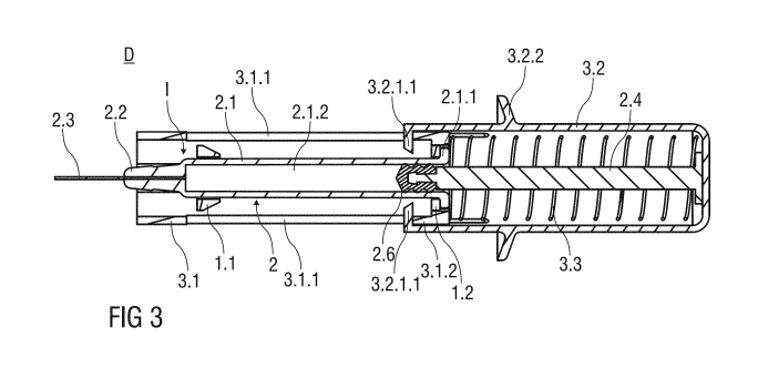
Figure 3 shows a sectional view of the injection device D before the
medication or drug
contained in the inner cavity 2.1.2 is delivered beneath the skin of the
patient. The
proximal collar 1.2 of the adaptor means 1 abuts two opposing and radial
inwardly
protruding inner ribs 3.1.2 formed to an inner surface of the support body
3.1. The inner
ribs 3.1.2 mount the adaptor means 1 to the support body 3.1 in a manner that
allows a
movement of the adaptor means 1 and the pre-filled syringe 2 retained therein
from the
first position I in a proximal direction.
Two longitudinal slots 3.1.1 are formed in opposite sides of the support body
3.1. Each
longitudinal slot 3.1.1 receives one radial projection 3.2.1.1 that moves
along the
longitudinal slot 3.1.1 when the injection stroke is carried out, whereby a
relative rotation
of outer body 3.2 with respect to the support body 3.1 is prevented. The
radial
projection 3.2.1.1 protrudes through the longitudinal slot 3.1.1, so that the
distal
collar 1.1 of the adaptor means 1 may be engaged by the radial projection
3.2.1.1 at the
end of the injection stroke.
AMENDED SHEET
CA 02823486 2013-06-28
PCT/EP 2011/074 274- 14-03-2013
11
Before the injection is performed, the radial projection 3.2.1.1 abuts the
inner rib 3.1.2 of
the support body 3.1 to limit a proximal movement of the outer body 3.2 with
respect to
the support body 3.1.
The piston rod 2.4 is connected to a piston 2.6 fluid-tightly sealing a
proximal end of the
inner cavity 2.1.2. The piston rod 2.4 abuts a proximal surface of the outer
body 3.2, so
that the piston rod 2.4 and the piston 2.6 may be moved by manually pushing
the outer
body 3.2 in the distal direction, whereby the medication expelled through the
hypodermic needle 2.3 of the pre-filled syringe 2.
A spring means 3.3 is arranged with the safety device 3 that biases the outer
body 3.2 .
with respect to the support body 3.1 in the proximal direction. Initially, the
spring
means 3.3 is arranged in a non-energized or only slightly energized state
within the
safety device 3. The spring means 3.3 shown in figure 3 is implemented as a
conventional compression spring that bears against the support body 3.1 in the
distal
direction and against the outer body 3.2 in the proximal direction. The
compression
spring is made from a metal.
Alternatively, the spring means 3.3 May be made from a plastics material to
reduce
production costs. The spring means 3.3 may have a different shape and design
suitable
for biasing the outer body 3.2 in the proximal direction.
Figure 4 shows a sectional view of the injection device D at the end of the
injection
stroke. The support body 3.1 is substantially received within the hollow outer
body 3.2.
The spring means 3.3 is fully energized and charged, so that the outer body
3.2 is
strongly biased with respect to the support body 3.1 in the proximal
direction. The piston
rod 2.4 is fully depressed into the barrel 2.1. The radial projection 3.2.1.1
engages the
distal collar 1.1, so that the adaptor means 1 with the pre-filled syringe 2
affixed thereto
may be retracted from the first position I in the proximal direction by a
proximal
movement of the outer body 3.2 with respect to the support body 3.1.
AMENDED SHEET
CA 02823486 2013-06-28
PCT/EP 2011/074 274- 14-03-2013
12
The distal collar 1.1 comprises a first tapered flank 1.1.2 that corresponds
to a second
tapered flank 3.2.1.2 of the radial projection 3.2.1.1. The first and second
tapered
flanks 1.1.2, 3.2.1.2 allow the radial projection 3.2.1.1 to pass the distal
collar 1.1 in the
distal direction, whereby the flexible arm 3.2.1 is deflected in a radial
outward direction.
Figure 5 shows a first sectional view of the injection device D after the
injection has
been carried out. The adaptor means 1 with the pre-filled 2 affixed thereto is
retained in
a retracted second position 11, wherein the hypodermic needle 2.3 of the pre-
filled
syringe is surrounded by the support body 3.1. The spring means 3.3 is in a
non-
energized or only slightly energized state.
Figure 6 shows a second sectional view of the injection device D. The
sectional plane
shown in figure 6 is rotated with respect to the first sectional view about an
angle of
approximately 90 degrees around the axis of the substantially cylindrical
safety device 3.
The locking projection 1.1.1 of the adaptor means 1 latches to a locking
recess 3.1.3
formed into the support body 3.1 to permanently lock the adaptor means 1 and
the pre-
filled syringe 2 affixed thereto in the second position II. A re-exposure of
the hypodermic
needle 2.3 of the pre-filled syringe 2 is thus prevented by the locking
projection 1.1.1
engaging the locking recess 3.1.3.
The locking projection 1.1.1 engaging the locking recess 3.1.3 is surrounded
by the
outer body 3.2 and is inaccessible from outside. This prevents a person from
tampering
with the locking projection 1.1.1 to unlock the adaptor means 1 from being
retained in
the second position II. The movement of the outer body 3.2 with respect to the
support
body 3.1 is limited by the radial projection 3.2.1.1 abutting a proximal end
of the
longitudinal slot 3.1.1, which prevents an exposure of the locking projection
1.1.1 and
the locking recess 3.1.3.
The injection is carried out as follows:
After removal of the needle cap 2.5, the hypodermic needle 2.3 is inserted
into the skin
of the patient. The flange (not illustrated) that provides an increased
surface area may
=
AMENDED SHEET
CA 02823486 2013-06-28
PCT/EP 2011/074 274- 14-03-2013
13
rest onto the skin of the patient to facilitate the injection of the
medication or drug. The
outer body 3.2 is pushed distally towards the skin of the patient to perform
the injection
stroke, whereby the outer body 3.2 moves with respect to the support body 3.1
in a
linear translatory movement. The piston 2.6 jointly moves with the outer body
3.2 in the
distal direction to dispose the medication contained in the inner cavity 2.1.2
beneath the
skin of the patient.
At the end of the injection stroke the medication is completely disposed and
the spring
means 3.3 is fully energized. The radial projection 3.2.1.1 clamps to the
distal collar 1.1.
Upon removal of the injection device D from the injection site, the spring
means 3.3
relaxes, whereby the outer body 3.2 moves proximally to retract the adaptor
means 1
together with the pre-filled syringe 2 from the first position I to the second
position II.
In the second position II, the locking projection 1.1.1 engages the locking
recess 3.1.3
to irreversibly lock the adaptor means 1 and the pre-filled syringe 2 to the
second
position II, so that a subsequent exposure of the hypodermic needle 2.3 is
prevented.
AMENDED SHEET
CA 02823486 2013-06-28
= PCT/EP 2011/074274 - 14-03-2013
14
List of References
1. adaptor means
1.1 distal collar
1.1.1 locking projection
1.1.2 first tapered flank
1.2 proximal collar
1.3 central aperture
1.4 clamp arms
2 pre-filled syringe
2.1 barrel
2.1.1 barrel collar
2.1.2 inner cavity
2.2 nozzle
2.3 hypodermic needle
2.4 piston rod
2.5 needle cap
2.6 piston
3 safety device
3.1 support body
3.1.1 longitudinal slot
3.1.2 inner rib
3.1.3 locking recess
3.2 outer body
3.2.1 flexible arm
3.2.1.1 radial projection
3.2.1.2 second tapered flank
3.2.2 gripping means
3.3 spring means
D injection device
first position
AMENDED SHEET
CA 02823486 2013-06-28
PCT/EP 2011/074 274- 14-03-2013
second position
AMENDED SHEET