Note: Descriptions are shown in the official language in which they were submitted.
1
CA 02823634 2013-07-02
WO 2012/093789 PCT/KR2011/009997
Description
Title of Invention: DISPLAY APPARATUS, 3D GLASSES, AND
CONTROL METHOD THEREOF
Technical Field
1111 This application claims the benefit of U.S. Provisional Patent
Application No.
61/429,641, filed on January 4, 2011 in the United States Patent and Trademark
Office,
and claims priority from Korean Patent Application No. 10-2011-0073649, filed
on
July 25, 2011 and Korean Patent Application No. 10-2011-0133358, filed on
December 13, 2011 in the Korean Intellectual Property Office, the disclosures
of which
are incorporated herein by reference.
[2] Apparatuses and methods consistent with the exemplary embodiments
relate to a
display apparatus, three-dimensional (3D) glasses and a control method
thereof, and
more particularly, a display apparatus capable of displaying a 3D image, 3D
glasses for
viewing the displayed 3D image, and a control method thereof.
Background Art
1131 A display apparatus capable of displaying a 3D image, which allows a
user to
recognize a 3D effect based on binocular parallax, alternately displays a left-
eye image
for a user's left eye and a right-eye image for a user's right eye, and
involves shutter
glasses that operate in accordance with the alternate display. As the display
apparatus
displays the left-eye image and the right eye image in each frame, the shutter
glasses
selectively transmit or block images to and from a user's left and right eyes.
For
instance, the shutter glasses open a shutter corresponding to a user's left-
eye when the
display apparatus displays the left-eye image, and the shutter glasses open a
shutter
corresponding to a user's right-eye when the display apparatus displays the
right-eye
image, thereby allowing a user to recognize a 3D effect of a 3D image.
Disclosure of Invention
Technical Problem
[4] When shutter glasses are employed in representing the 3D image, it is
important to
synchronize the left and right image frames displayed on the display apparatus
with
operations of the left and right shutters in the shutter glasses. Therefore,
the display
apparatus may include a control for the shutters of the shutter glasses, or
the shutter
glasses themselves may include a control for the shutters.
1151 In order to properly establish synchronization, the display apparatus
and the shutter
glasses are first paired with each other. The display apparatus often serves
as a main
agent of a pairing process, and is thus burdened with a pairing operation.
Therefore,
there is a need of solving this problem.
2
CA 02823634 2013-07-02
WO 2012/093789 PCT/KR2011/009997
Solution to Problem
[6] One or more exemplary embodiments may provide a display apparatus, 3D
glasses
and a control method thereof, which can perform operation control for shutters
of the
3D glasses.
1171 One or more exemplary embodiments may provide a method of pairing a
display
apparatus with 3D glasses, and the display apparatus and 3D glasses which
carry out
the same.
1181 According to an aspect of an exemplary embodiment, a method of
controlling three-
dimensional (3D) glasses for a display apparatus is provided. The method
includes:
synchronizing clocks for communicating with the 3D glasses; generating drive
timing
information for driving shutters of the 3D glasses from the synchronized
clocks and a
frame sync signal of a displayed image; and transmitting a glasses control
message,
including the drive timing information, to the 3D glasses.
1191 The synchronizing the clocks may further include transmitting a count
value of the
clocks of the display apparatus to the 3D glasses.
[10] The count value of the clocks may be transmitted using a reconnection
train message
for paring between the display apparatus and the 3D glasses.
[11] The drive timing information may include a count value of the clocks
of the display
apparatus corresponding to the frame sync signal.
[12] The glasses control message may further include shutter-operation
delay information
of the 3D glasses.
[13] The shutter-operation delay information may include delay information
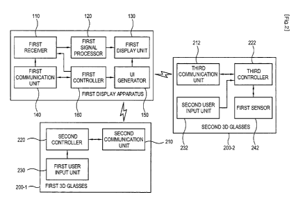
regarding a
timing between a reference time determined by the drive timing information and
a time
when a shutter is to be opened or closed.
[14] The glasses control message may further include frame rate information
determined
in accordance with the frame sync signal.
[15] The glasses control message may be transmitted in a longer cycle than
the frame sync
signal to prevent the 3D glasses from 3D mode off.
[16] The frame sync signal may include a vertical sync (Vsync) signal of
the image.
[17] The method may further include acquiring information about a display
unit of the
display apparatus; and modifying duty of the drive timing information based on
the
acquired information about the display unit.
[18] According to an aspect of an exemplary embodiment, a display apparatus
is provided
including: a display unit; a communication unit which synchronizes clocks for
commu-
nicating with three-dimensional (3D) glasses; a signal generator which
generates drive
timing information for driving shutters of the 3D glasses from the
synchronized clocks
and a frame sync signal of an image displayed on the display unit; and a
controller
3
CA 02823634 2013-07-02
WO 2012/093789 PCT/KR2011/009997
which controls the communication unit to transmit a glasses control message
including
the drive timing information to the 3D glasses.
[19] The communication unit may transmit a count value of the clocks of the
display
apparatus to the 3D glasses so as to synchronize the clocks.
[20] The count value may be transmitted using a reconnection train message
for paring
between the display apparatus and the 3D glasses.
[21] The drive timing information may include a count value of the clocks
of the display
apparatus corresponding to the frame sync signal.
[22] The glasses control message may further include shutter-operation
delay information
of the 3D glasses.
[23] The shutter-operation delay information may include delay information
regarding a
timing between a reference time determined by the drive timing information and
a time
when a shutter is to be opened or closed.
[24] The glasses control message may further include frame rate information
determined
in accordance with the frame sync signal.
[25] The glasses control message may be transmitted in a longer cycle than
the frame sync
signal to prevent the 3D glasses from 3D mode off.
[26] The frame sync signal may include a vertical sync signal (Vsync) of
the image.
[27] The controller may acquire information about the display unit, and
modify duty of
the drive timing information based on the acquired information about the
display unit.
[28] According to an aspect of an exemplary embodiment, a method of
controlling
shutters of three-dimensional (3D) glasses is provided. The method includes:
syn-
chronizing clocks for communicating with a display apparatus; receiving a
glasses
control message, generated using the synchronized clock and a frame sync
signal of a
displayed image and including drive timing information for driving the
shutters of the
3D glasses, from the display apparatus; and controlling the shutters to be
opened or
closed in sync with the drive timing information.
[29] The synchronizing the clocks may further include receiving a count
value of the
clocks of the display apparatus from the display apparatus.
[30] The count value may be received using a reconnection train message for
paring
between the display apparatus and the 3D glasses.
[31] The drive timing information may include a count value of the clocks
of the display
apparatus corresponding to the frame sync signal.
[32] The glasses control message may further include shutter-operation
delay information
of the 3D glasses.
[33] The shutter-operation delay information may include delay information
regarding a
timing between a reference time determined by the drive timing information and
a time
when a shutter is to be opened or closed.
4
CA 02823634 2013-07-02
WO 2012/093789 PCT/KR2011/009997
[34] The glasses control message may further include frame rate information
determined
in accordance with the frame sync signal.
[35] The receiving the glasses control message may include receiving the
glasses control
message in a longer cycle than the frame sync signal to prevent the 3D glasses
from 3D
mode off.
[36] The frame sync signal may include a vertical sync (Vsync) signal of
the image.
[37] The method may further include stopping opening or closing the
shutters if no
glasses control message is received for a preset period of time.
[38] The stopping opening or closing the shutters may include stopping the
shutters in an
open position.
[39] The controlling the shutters to be opened or closed may include
controlling an
operation timing and a duty of the shutters based on information about shutter-
open
delay and information about shutter-close delay.
[40] The controlling the shutters to be opened or closed may include
generating a first
clock signal having a frequency which is half of a shutter operating
frequency;
generating a second clock signal having a phase which is different from a
phase of the
first clock signal by a quarter cycle; and generating a shutter operation
driving signal
by inverting an XOR value about logic levels of the first and second clock
signals.
[41] The controlling the shutters to be opened or closed may include
controlling a duty of
the shutter operation driving signal by shifting the first clock signal or the
second clock
signal in accordance with the shutter-operation delay information.
[42] According to an aspect of an exemplary embodiment, three-dimensional
(3D) glasses
are provided including: a communication unit which communicates with a display
apparatus; a shutter unit which includes a left-eye shutter and a right-eye
shutter to be
alternately opened and closed; and a controller which synchronizes clocks for
commu-
nicating with the display apparatus, controls the communication unit to
receive a
glasses control message, generated using the synchronized clocks and a frame
sync
signal of a displayed image and including drive timing information fro driving
shutters
of the 3D glasses, from the display apparatus, and controls the shutters to be
opened or
closed in sync with the received drive timing information.
[43] The controller may synchronize the clocks by receiving a count value
of the clocks of
the display apparatus from the display apparatus.
[44] The count value may be received using a reconnection train message for
paring
between the display apparatus and the 3D glasses.
[45] The drive timing information may include a count value of the clocks
of the display
apparatus at a point of time related to the frame sync signal.
[46] The glasses control message may further include shutter-operation
delay information
of the 3D glasses.
5
CA 02823634 2013-07-02
WO 2012/093789 PCT/KR2011/009997
[47] The shutter-operation delay information may include delay information
regarding a
timing between a reference time determined by the sync signal and a time when
a
shutter is opened or closed.
[48] The glasses control message may further include frame rate information
determined
by the frame sync signal.
[49] The glasses control message may be received in a longer cycle than the
frame sync
signal to prevent the 3D glasses from 3D mode off.
[50] The frame sync signal may include a vertical sync (Vsync) signal of
the image.
[51] The controller may control the shutter unit to stop opening or closing
the shutters if
no glasses control message is received for a preset period of time.
[52] The controller may stop opening or closing the shutters by stopping
the shutters in an
open position.
[53] The controller may control the shutters to be opened or closed by
controlling an
operation timing and a duty of the shutters based on information about shutter-
open
delay and information about shutter-close delay.
[54] The controller may control the shutters to be opened or closed by
generating a first
clock signal having a frequency which is half of a shutter operating
frequency;
generating a second clock signal having a phase which is different form a
phase of the
first clock signal by a quarter cycle; and generating a shutter operation
driving signal
by inverting an XOR value about logic levels of the first and second clock
signals.
[55] The controller may control the shutters to be opened or closed by
controlling a duty
of the shutter operation driving signal by shifting the first clock signal or
the second
clock signal in accordance with the shutter-operation delay information.
[56]
[57] The controller may control the shutter unit to stop opening or closing
the shutters if
receiving no glasses control message for a preset time.
[58] The controller may stop opening or closing the shutters by stopping
the shutters as
being opened.
[59] The controller may control the shutters to be opened or closed by
controlling
operation timing and duty of the shutters based on information about shutter-
open
delay and information about shutter-close delay.
[60] The controller may control the shutters to be opened or closed by
generating a first
clock signal having a half frequency of a shutter operating frequency;
generating a
second clock signal different in a phase of a quarter cycle from the first
clock signal;
and generating a shutter operation driving signal by inverting an XOR value
about
logic levels of the first and second clock signals.
[61] The controller may control the shutters to be opened or closed by
controlling the duty
of the shutter operation driving signal by shifting the first clock signal or
the second
6
CA 02823634 2013-07-02
WO 2012/093789 PCT/KR2011/009997
clock signal in accordance with the shutter-operation delay information.
[62] According to an aspect of another exemplary embodiment, a pairing
method of a
display apparatus communicating with 3D glasses is provided. The method
includes:
receiving a scanning message for pairing; transmitting a response message to
the
scanning message; receiving an acknowledgement message to the response
message;
and displaying a popup image of notifying successful pairing with the 3D
glasses in
response to the acknowledgement message.
[63] The response message may include a threshold received signal strength
indication
(RSSI) value information corresponding to the 3D glasses.
[64] The threshold RSSI value information may be different in accordance
with models of
the 3D glasses.
[65] The threshold RSSI value information may be different in accordance
with whether
the display apparatus is in a home mode or a show room mode.
[66] The popup image may notify pairing with the 3D glasses among the 3D
glasses and
other devices.
[67] According to an aspect of another exemplary embodiment, a display
apparatus is
provided including: a communication unit which communicates with 3D glasses; a
display unit; and a controller which receives a scanning message for pairing
with the
3D glasses, transmits a response message to the scanning message, receives an
ac-
knowledgement message to the response message, and displays a popup image of
notifying successful pairing with the 3D glasses in response to the
acknowledgement
message.
[68] The response message may include a threshold received signal strength
indication
(RSSI) value information corresponding to the 3D glasses.
[69] The threshold RSSI value information may be different in accordance
with models of
the 3D glasses.
[70] The threshold RSSI value information may be different in accordance
with whether
the display apparatus is in a home mode or a show room mode.
[71] The popup image may notify pairing with the 3D glasses among the 3D
glasses and
other devices.
[72] According to an aspect of another exemplary embodiment, a pairing
method of 3D
glasses communicating with a display apparatus is provided. The method
includes:
transmitting a scanning message for pairing; receiving a response message to
the
scanning message from the display apparatus; comparing a received signal
strength in-
dication (RSSI) value of the response message with a threshold value; and
determining
the display apparatus as a pairing object if the RSSI value is equal to or
higher than the
threshold value.
11731 If a plurality of display apparatuses have the RSSI values higher
than the threshold
7
CA 02823634 2013-07-02
WO 2012/093789 PCT/KR2011/009997
value, the determining the pairing object may include determining the display
apparatus having the maximum RSSI value as the pairing object.
[74] The threshold value may be received from the display apparatus.
[75] The method may further include sending the display apparatus an
acknowledgement
message to the response message.
[76] The method may further include powering off the 3D glasses if
receiving no response
message to the scanning message from the display apparatus for a predetermined
time.
[77] According to an aspect of another exemplary embodiment, 3D) glasses
are provided
including: a communication unit which communicates with a display apparatus;
and a
controller which transmits a scanning message for pairing with the display
apparatus,
controls the communication unit to receive a response message to the scanning
message from the display apparatus, compares a received signal strength
indication
(RSSI) value of the response message with a threshold value, and determines
the
display apparatus as a pairing object if the RSSI value is equal to or higher
than the
threshold value.
[78] If a plurality of display apparatuses have the RSSI values higher than
the threshold
value, the controller may determine the display apparatus having the maximum
RSSI
value as the pairing object.
[79] The threshold value may be received from the display apparatus.
[80] The controller may control the communication unit to send the display
apparatus an
acknowledgement message to the response message.
[81] The controller may power off the 3D glasses if receiving no response
message to the
scanning message from the display apparatus for a predetermined time.
Advantageous Effects of Invention
[82] As described above, there are provided a display apparatus, 3D glasses
and a control
method thereof, which can perform operation control for shutters of the 3D
glasses.
[83] Also, there are provided a method of pairing a display apparatus with
3D glasses, and
the display apparatus and 3D glasses which carry out the same.
Brief Description of Drawings
[84] The above and/or other aspects will become apparent and more readily
appreciated
from the following description of exemplary embodiments, taken in conjunction
with
the accompanying drawings, in which:
[85] FIG. 1 is a schematic view of a display system including a display
apparatus and 3D
glasses according to an exemplary embodiment;
[86] FIG. 2 is a control block diagram of the display apparatus and the 3D
glasses
according to an exemplary embodiment;
11871 FIG. 3 is a flowchart of pairing the display apparatus and the 3D
glasses of FIG. 2;
8
CA 02823634 2013-07-02
WO 2012/093789 PCT/KR2011/009997
[88] FIG. 4 illustrates a message scan for pairing between the display
apparatus and the
3D glasses of FIG. 2;
[89] FIG. 5 is a control block diagram of the display apparatus and the 3D
glasses of FIG.
2;
[90] FIG. 6 illustrates shutter-operation delay information of the display
apparatus of FIG.
5;
[91] FIGs. 7A to 7C illustrate duty cycles of 3D glasses of FIG. 5;
[92] FIG. 8 is a flowchart showing a control operation of the display
apparatus of FIG. 5;
and
[93] FIG. 9 is a flowchart showing a control operation of the 3D glasses of
FIG. 5.
Best Mode for Carrying out the Invention
[94] Below, exemplary embodiments will be described in detail with
reference to ac-
companying drawings so as to be easily realized by a person having ordinary
knowledge in the art. The exemplary embodiments may be embodied in various
forms
without being limited to the exemplary embodiments set forth herein.
Descriptions of
well-known parts are omitted for clarity, and like reference numerals refer to
like
elements throughout.
[95] FIG. 1 is a schematic view of a display system including a display
apparatus and 3D
glasses according to an exemplary embodiment.
[96] As shown therein, the display system includes a first display
apparatus 100 and 3D
glasses 200. The 3D glasses may be provided in plural. Thus, the plurality of
3D
glasses may operate in association with one display apparatus. In the display
system,
the first display apparatus 100 may support a remote controller (not shown,
for
example, a QWERTY remote controller), a headset (not shown, for example, a
2A2DP
stream), a cell phone (not shown) containing an application corresponding to a
function of a remote controller, a mouse device (not shown, for example, a
gestural
remote controller), etc. as well as the 3D glasses. The first display
apparatus 100 does
not have to support keyboards, but may maintain this support option if
desired. The
display system shown in FIG. 1 corresponds to a home mode of the display
apparatus.
However, the display system may also be configured to operate in other
environments.
[97] In a display apparatus which employs infrared (IR) to communicate with
an external
device, control data can be transmitted from the display apparatus to the
external
device, but not from the external device to the display apparatus. Thus, it is
impossible
for the external device to request a predetermined function or verify the
state of the
external device.
[98] However, according to the exemplary embodiment as shown in FIG. 1,
commu-
nication between the first display apparatus 100 and the 3D glasses is
achieved by
9
CA 02823634 2013-07-02
WO 2012/093789 PCT/KR2011/009997
radio frequency (RF) transmissions. The RF communication may correspond to
Bluetooth or Zigbee. Through the RF communication, the first display apparatus
100
and the 3D glasses 200 can interactively communicate with each other.
Therefore, the
3D glasses 200 can autonomously carry out a pairing process prior to
establishing syn-
chronization with the display apparatus or can transmit glasses information to
the first
display apparatus 100.
[99] Meanwhile, the first display apparatus 100 may support a general
pairing process for
a display apparatus to then establish synchronization with a television (TV)
or
headphones, or another external device.
[100] According to the present exemplary embodiment, the first display
apparatus 100 may
carry out a pairing process with a headset (not shown), a remote controller
(not
shown), a cell phone (not shown), etc. as well as with the 3D glasses 200. If
a plurality
of display apparatuses are provided, that is, if the first display apparatus
100 is in a
show room mode (not shown), the first display apparatus 100 may also perform a
pairing with other display apparatuses.
[101] Below, the first display apparatus 100 and the 3D glasses 200-1 and
200-2 will be
described in detail with reference to FIG. 2. FIGs. 2 to 4 are for explaining
a pairing
process based on interactive communication between the first display apparatus
100
and the 3D glasses 200.
[102] The first display apparatus 100 includes a first receiver 110, a
first signal processor
120, a first display unit 130, a first communication unit 140, a user
interface (UI)
generator 150, and a first controller 160 controlling the other units.
[103] The first display apparatus 100 is a display apparatus capable of
displaying both a
monocular image (or two-dimensional (2D) image) and a binocular image (or 3D
image), and may be a TV, a personal computer (PC), a projector, etc. capable
of
displaying a 3D image.
[104] The first receiver 110 includes a receiver (not shown) receiving a
predetermined
video signal from an external video source (not shown).. The video source may
be an
external PC (not shown), a server (not shown) providing a video signal through
a
network, a transmitter (not shown) of a broadcasting station capable of
transmitting a
broadcasting signal through airwaves or cables, etc.
[105] The first signal processor 120 processes the received video signal to
be displayed on
the display unit 130. The video signal may include a 2D image or a 3D image.
The
video processor (not shown) demodulates the received video signal to be
displayed on
the display unit 130, and may perform decoding and encoding corresponding to
various video formats, de-interlacing, frame refresh rate conversion, scaling,
noise
reduction for enhancing picture quality, detail enhancement, line scanning, or
the like
process in addition to the foregoing process. If the received video signal is
a 3D video
10
CA 02823634 2013-07-02
WO 2012/093789 PCT/KR2011/009997
signal and the 3D video signal has various formats, the signal processor 120
may
process the 3D video signal corresponding to the various formats to be
displayed on
the display unit 130. The 3D video signal may have a top-bottom format, a side-
by-side format, a horizontal interleave format, a checker board format, a
sequential
frame format, etc.
[1061
111071 If the pairing with the 3D glasses 200 is successfully completed by
the first commu-
nication unit 140, the first display unit 130 displays a popup image notifying
a viewer
of the successful pairing. Also, the first display unit 130 basically displays
an input
video signal processed by the first signal processor 120, and alternately
displays a left-
eye image and a right-eye image if the video signal is a 3D signal. The first
display
unit 130 includes a display panel (not shown) displaying an image and a panel
driver
(not shown). The display panel (not shown) may be a liquid crystal display
(LCD)
panel having a liquid crystal layer, an organic light emitting diode (OLED)
panel
having an organic light emitting layer, a plasma display panel (PDP), etc.The
first
communication unit 140 can communicate with the 3D glasses 200 and may perform
RF communication. For example, the first communication unit 140 may include a
Bluetooth communication module, a Zigbee communication module, etc. The commu-
nication may be based on a Bluetooth communication protocol or a Zigbee commu-
nication protocol. Through the first communication unit 140, the first display
apparatus
100 may transmit and receive data, a shutter sync signal, a control signal,
etc. to and
from the 3D glasses 200.
111081 The communication unit 140 receives a scanning message for pairing
with the 3D
glasses 200, transmits a response message to the scanning, and receives an
acknowl-
edgement message to the response message under control of the first controller
160.
The pairing process for will be described in detail with reference to FIGs. 3
and 4.
111091 The UI generator 150 generates the popup image providing
notification of the
successful pairing with the 3D glasses 200 and displays it on the first
display unit 130
under control of the first controller 160. The popup image contains
information about
the pairing. For example, the popup image may provide identification
information of
the 3D glasses 200 (for example, a media access control (MAC) address or a
Bluetooth
device (BD) address), and information about whether the pairing is successful.
If the
first display apparatus 100 pairs with the remote controller (not shown), the
headset
(not shown), etc. in addition to the 3D glasses, the information about the
pairing may
further include the types of electronic devices with which the first display
apparatus
100 is paired. Through the popup image, a user can be informed which
electronic
device tries to pair with the first display apparatus 100 and succeeds in the
pairing.
111101 The first controller 160 controls the first communication unit 140
to receive a
11
CA 02823634 2013-07-02
WO 2012/093789 PCT/KR2011/009997
scanning message for the pairing with the 3D glasses 200, transmit a response
message
to the scanning, and receive an acknowledge message to the response message,
and
controls the first display unit 130 to display the popup image for providing
information
of the pairing with the 3D glasses in response to the acknowledge message. The
pairing process prior to establishing synchronization will be described in
detail with
reference to FIGs. 3 and 4.
[111] The first display apparatus 100 may further include a user input unit
(not shown).
The user input unit (not shown) includes a user interface for receiving a
user's input,
which may be provided in the form of a button on the first display apparatus
100,
provided as a touch panel for a touch screen, or provided in various forms
such as a
wired or wireless remote controller, a keyboard, etc.
[112] Referring to FIG. 1, the first 3D glasses 200-1 include a second
communication unit
210, a second controller 220, and a first user input unit 230. Also, the
second 3D
glasses 200-2 include a third communication unit 212, a third controller 222,
a second
user input unit 232, and a first sensor 242. The first 3D glasses 200-1 and
the second
3D glasses 200-2 are different in that the second 3D glasses include the first
sensor
242. For example, the first 3D glasses 200-1 are general 3D glasses (in box
glasses),
and the second 3D glasses 200-2 are sensor 3D glasses (sensor glasses).
[113] The second communication unit 210 and the third communication unit
212 com-
municate with the first display apparatus 100, and may perform RF
communication.
For example, each of the second communication unit 210 and the third
communication
unit 212 may include a Bluetooth communication module or a Zigbee
communication
module, and communicate with the first display apparatus 100 in accordance
with a
Bluetooth communication protocol or a Zigbee communication protocol. The first
3D
glasses 200-1 and the second 3D glasses 200-2 may transmit and receive data, a
shutter
sync signal, and a control signal, etc. to and from the first display
apparatus 100
through the second communication unit 210 and the third communication unit
212, re-
spectively.
[114] The second controller 220 and the third controller 222 respectively
control the
second communication unit 210 and the third communication unit 212 to transmit
the
scanning message for pairing with the first display apparatus 100, and receive
the
response messages to the scanning from the first display apparatus 100.
Further, the
second controller 220 and the third controller 222 each compare a received
signal
strength indicator (RSSI) value of the response message with a threshold
value, and
determine the first display apparatus as an object for pairing if the RSSI
value is equal
to or higher than the threshold value. The pairing process prior to
establishing synchro-
nization will be described in detail with reference to FIGs. 3 and 4.
111151 If the first user input unit 230 and the second user input unit 232
are user interfaces
12
CA 02823634 2013-07-02
WO 2012/093789 PCT/KR2011/009997
for receiving a user's input, which receive a user's selection related to the
function or
operation of the 3D glasses 200-1 and 200-2. The first user input unit 230 and
the
second user input unit 232 may include at least one key button. For example,
the first
user input unit 230 may be achieved by a power button for turning on/off the
first 3D
glasses 200-1. The power button signal may be recognized when the button is
pressed
down, rather than when the button is released. When the power button is
pressed down,
the 3D glasses are toggled between power on status and power off (sleep mode)
status.
For example, the second user input unit 232 may be achieved by a pairing
button and/
or reset button of the second 3D glasses 200-2.
[116] The first user input unit 230 and the second user input unit 232 may
receive a user's
input for turning on/off the 3D glasses 200-1 and 200-2. For example, in the
case of the
first 3D glasses 200-2, if the power button provided in the first 3D glasses
200-1 is
held down shortly (for example, for less than 3 seconds, for less than 2
seconds, or for
less than 1 second), the first 3D glasses 200-1 are powered on. If the power
button is
held down again shortly (for example, for less than 3 seconds, for less than 2
seconds,
or for less than 1 second), while the first 3D glasses 200-1 is powered on,
the first 3D
glasses 200-1 are powered off. For example, in the case of the second 3D
glasses
200-2, the second 3D glasses 200-2 are first taken out from a box and a
pairing button
provided in the second 3D glasses 200-2 is pressed down (for example, for less
than 3
seconds, for less than 2 seconds, or for less than 1 second), the second 3D
glasses
200-2 is powered on. After the second 3D glasses 200-2 are first turned on,
the second
3D glasses 200-2 may become powered on in accordance with a sense of the first
sensor 242 (to be described later). Accordingly, the glasses power may be
turned on
using the first sensor 242 once the sensor 3D glasses are powered on. If the
pairing
button is held down again shortly (for example, for less than 3 seconds, for
less than 2
seconds, or for less than 1 second) in order to power off the second 3D
glasses 200-2,
the second 3D glasses 200-2 are powered off.
[117] The first user input unit 230 and the second user input unit 232 may
receive a user's
input for initiate the pairing for the 3D glasses 200-1 and 200-2 and the
first display
apparatus. For example, in the case of the first 3D glasses 200-1, if the
power button
provided in the first 3D glasses 200-1 is held down for a predetermined time
(for
example, for less than 3 seconds, for less than 2 seconds, or for less than 1
second),
even though the first 3D glasses 200-1 are already powered on or in a powered
off
state, the second controller 220 may determine that proximity pairing with the
first
display apparatus 100 is requested by a user. For example, in the case of the
second 3D
glasses 200-2, if the pairing button provided in the second 3D glasses 200-2
is pressed
down even though the second 3D glasses 200-2 are already powered on or in a
powered off state, the third controller 222 may determine that proximity
pairing with
13
CA 02823634 2013-07-02
WO 2012/093789 PCT/KR2011/009997
the first display apparatus 100 is requested by a user. A signal from the
power button
may be recognized when the button is pressed down, rather than when the button
is
released.
[118] The first sensor 242 can sense a predetermined motion or a touch of
the second 3D
glasses 200-2. For example, the first sensor 242 includes a touch sensor or an
ac-
celerometer. The third controller 222 can control the power on/off of the
second 3D
glasses 200-2 in accordance with sense results of the first sensor 242. After
the second
3D glasses 200-2 are first turned on by the pairing button, if the
accelerometer senses
the motion of the second 3D glasses 200-2 (for example, senses that a user
picks up the
second 3D glasses 200-2) or the touch sensor senses the touch of the second 3D
glasses
200-2 (for example, senses that the second 3D glasses 200-2 are put on a
user's face),
the third controller 222 can power on the second 3D glasses 200-2. Meanwhile,
if the
first sensor 242 senses no motion or no touch for a predetermined time (for
example,
for 5 minutes, for 1 minute, or for 5 seconds) after the power on state, the
third
controller 222 may power off the second 3D glasses 200-2.
[119] The 3D glasses 200 may further include a battery (not shown) that
supplies operation
power to the 3D glasses 200. The operation power provided by the battery is
under
control of the controller 220, 222).
[120] FIG. 3 is a flowchart of pairing the first display apparatus 100 and
the 3D glasses
200, and FIG. 4 illustrates a message scan for pairing between the first
display
apparatus and the 3D glasses 200 of FIG. 2.
[121] In this exemplary embodiment, the first display apparatus 100 and the
3D glasses 200
can support a proximity pairing function using the RSSI.
[122] As shown in the user input units 230 and 232 referring to FIG. 3, a
paring request
signal is requested from a user through the user input unit 230 or 232
provided in the
3D glasses 200. When the 3D glasses 200 is first taken out of a box (i.e.,
having an out
of box scenario), it is defined that the 3D glasses 200 has no MAC address or
no BD
address of the display apparatus. If the power button is held down for a
predetermined
time (e.g., for 3 seconds, or for 2 seconds) even if the general 3D glasses
(e.g., the first
3D glasses 200-1) are already powered on or are in a powered off state, or if
the
pairing button is held down for a predetermined time (e.g., for 2 seconds)
even if the
sensor 3D glasses (e.g., the second 3D glasses 200-2) are already powered on
or are in
a powered off state, it is regarded that a pairing request signal is indicated
by a user,
thereby starting the proximity pairing process. At this time, the
predetermined time
refers to a time during which the pairing button is pressed down.
[123] The pairing process is tried for a predetermined time (e.g., 5
minutes). If the pairing
process is not completed within the predetermined (e.g., 5 minutes), the 3D
glasses 200
may be turned off. Also, if a power button of general 3D glasses of a pairing
button of
14
CA 02823634 2013-07-02
WO 2012/093789 PCT/KR2011/009997
sensor 3D glasses is pressed down during the pairing process, the 3D glasses
200 may
be turned off.
[124] When receiving the pairing request signal from a user, the controller
220 or 222 of
the 3D glasses 200 controls the communication unit 210 or 212 to transmit the
scanning message for the pairing. The transmission of the scanning message may
be
two transmissions of inquiry scan having a period of 1.28s, and may be two
trans-
missions of inquiry scan having a period of 640ms. In this exemplary
embodiment, the
proximity pairing is defined as checking all display apparatuses above a
threshold
value for two full scan periods.
[125] In response to the transmission of the scanning message for the
pairing from the 3D
glasses 200, the first display apparatus 100 transmits the response message to
the 3D
glasses 200.
[126] FIG. 4 shows an inquiry scan of the 3D glasses 200 and a page scan of
the first
display apparatus 100. (A) of FIG. 4 shows a case in which the first display
apparatus
100 is powered on, and (B) shows a case in which the first display apparatus
100 is
powered off. In the case of (A) in FIG. 4, the 3D glasses 200 transmit the
inquiry scan
having a period of 1.28s to the first display apparatus 100, and the inquiry
scan
includes a total two of full inquiry scan sections. The first display
apparatus 100 con-
tinuously performs a page scan having a period of 50ms. During the total of
the two
full inquiry scan sections of the 3D glasses 200, if the inquiry scan occurs
at the same
time as the page scan of the first display apparatus 100, the first display
apparatus 100
transmits the response message to the 3D glasses 200 in response to the
inquiry scan.
In the case of (B) of FIG. 4, the 3D glasses 200 transmit an inquiry scan
section having
a period of 2.56s, but the first display apparatus 100 cannot transmit the
response
message since it is powered off and the page scan is not performed.
[127] The response message may include at least one of identification
information of the
first display apparatus 100; a threshold RSSI value information corresponding
to the
3D glasses 200, through which the 3D glasses can determine a device for
concluding
the proximity pairing; and an RSSI value information of the response message.
Thus,
the RSSI value is set up in the first display apparatus 100 and transmitted to
the 3D
glasses 200.
[128] The threshold of the RSSI value may vary depending on the model of
the 3D glasses
200. Accordingly, the RSSI value is transmitted from the first display
apparatus 100 to
the 3D glasses 200. For example, the general 3D glasses and the sensor glasses
may re-
spectively receive response messages from the first display apparatus which
include
different RSSI values from each other.
[129] Also, the threshold RSSI value information may vary depending on
modes of the first
display apparatus 100. Therefore, during the proximity pairing process, the
first display
15
CA 02823634 2013-07-02
WO 2012/093789 PCT/KR2011/009997
apparatus 100 communicates to the 3D glasses 200 whether it is in a home mode
or a
show room mode. For example, the first display apparatus 100 may transmit a
different
response message containing the threshold RSSI value information depending on
whether it is in the home mode (see FIG. 1) or the show room mode (not shown).
Here,
the home mode or the show room mode of the first display apparatus 100 is
selected by
a user using the user interface generated by the display apparatus 100.
[130] When the 3D glasses 200 receive a response message, the 3D glasses
200 compare
the RSSI value of the response message with the threshold RSSI value. If the
RSSI
value of the response message is equal to or higher than the threshold RSSI
value, the
3D glasses 200 transmit the acknowledge message to the corresponding display
apparatus 100.
[131] If the 3D glasses 200 receive two or more response messages (A), the
3D glasses 200
select the display apparatus meeting the response message having the highest
RSSI
value among the RSSI values of the plural response messages, and then transmit
the
acknowledge message to the selected display apparatus.
[132] If the 3D glasses 200 receive no response message, the 3D glasses 200
continue the
transmission of the scanning message for the pairing for 5 minutes or for
another
period of time as would be understood by one of skill in the art. If the 3D
glasses have
still received no response message even after 5 minutes, the 3D glasses 200
determine
the proximity pairing to have failed, and thus the controller 220 or 222 of
the 3D
glasses 200 may power off the 3D glasses 200.
[133] If the 3D glasses 200 successfully pair with the first display
apparatus 100, the 3D
glasses 200 indicate that the pairing is completed as shown in tables 1 and 2,
discussed
below, through an LED display unit (not shown).
[134] The acknowledge message transmitted from the 3D glasses 200 to the
first display
apparatus 100 in response to the response message may contain information
about the
identification, the state, and the pairing success of the 3D glasses 200.
[135] If the first display apparatus 100 receives the acknowledge message
from the 3D
glasses 200, it displays a popup screen for informing a user that the pairing
is suc-
cessfully completed. Thus, the popup screen notifies the user that, among a
possible
plurality of external devices, the 3D glasses are paired with the first
display apparatus
100. Also, the popup image may further contain not only the message of
notifying of
the successful pairing but also a message of identifying the type or types of
the paired
device (e.g., the 3D glasses, the remote controller, the headset, etc.).
[136] FIGs. 5 to 9 are to explain a shutter operation control of a display
apparatus 300 and
3D glasses 400 according to another exemplary embodiment.
[137] FIG. 5 is a control block diagram of a display apparatus 300 and 3D
glasses 400.
111381 As shown in FIG. 5, the second display apparatus 300 includes a
second receiver
16
CA 02823634 2013-07-02
WO 2012/093789 PCT/KR2011/009997
310, a second signal processor 320, a second display unit 330, a fourth
communication
unit 340 and a fourth controller 360, which are the same as those of the first
display
apparatus 100 shown in FIG. 2, and thus repetitive descriptions thereof will
be avoided
as necessary. The second display apparatus 300 also includes a signal
generator 350.
[139] Like the first display apparatus 100, the second display apparatus
300 is a display
apparatus capable of displaying both a monocular image and a binocular image,
and
may be a TV, a personal computer (PC), a projector, etc. capable of displaying
a 3D
image. Further, the second display apparatus 300 includes a receiver (not
shown), a
video processor (not shown), a display unit (not shown) and a user input unit
(not
shown), which are the same as/similar to those of the first display apparatus
100 and
thus repetitive descriptions thereof will be avoided.
[140] The fourth communication unit 340 communicates with the 3D glasses
400. If the
second display apparatus 300 and the 3D glasses 400 start the proximity
pairing with
each other by the method described with reference to FIGs. 3 and 4, they have
in-
formation needed for the interactive communication. Then, the fourth
communication
unit 340 synchronizes clocks for communicating with the 3D glasses 400 under
control
of the fourth controller 360 so that the second display apparatus 300 can
transmit a
control signal to the 3D glasses 400. Like the first communication unit 140 of
the first
display apparatus 100, the fourth communication unit 340 can do the RF commu-
nication. For example, the fourth communication unit 340 may include a
Bluetooth
communication module, a Zigbee communication module, etc. If there is the
Bluetooth
communication between the second display apparatus 300 and the third glasses
400,
the fourth communication unit 340 performs the communication based on a
Bluetooth
communication protocol. For the Bluetooth communication with the 3D glasses
400,
the fourth communication unit 340 synchronizes Bluetooth clocks under control
of the
fourth controller 360. Each of the second display apparatus 300 and the 3D
glasses 400
includes a local oscillator (not shown) for generating the Bluetooth clocks.
Since
Bluetooth communication channels are distinguished by the generated Bluetooth
clocks, the Bluetooth clocks respectively generated by the second display
apparatus
300 and the 3D glasses 400 have to be synchronized for transmitting and
receiving data
to and from each other. For the synchronization of the Bluetooth clocks, the
fourth
communication unit 340 transmits a reconnection train message containing a
count
value of the Bluetooth clock of the second display apparatus 300 to the 3D
glasses 400.
The 3D glasses 400 receives the reconnection train message for a predetermined
period
of time and extracts the current count value of the Bluetooth clock of the
second
display apparatus 300 from the received reconnection train message. The 3D
glasses
400 control the local oscillator to generate the Bluetooth clocks in
accordance with the
current count value of the Bluetooth clock of the second display apparatus
300. For
17
CA 02823634 2013-07-02
WO 2012/093789 PCT/KR2011/009997
example, the count value of the Bluetooth clock in the 3D glasses is set up in
ac-
cordance with the current count value of the received Bluetooth clock, so that
the
Bluetooth clock of the 3D glasses can be synchronized with the Bluetooth clock
of the
second display apparatus.
[141] Consequently, the Bluetooth clocks of the second display apparatus
300 and 3D
glasses 400 are synchronized with each other to transmit and receive data to
and from
each other.
[142]
[143] The signal generator 350 generates drive timing information of the 3D
glasses 400
based on the synchronized clocks and a frame sync signal of an image displayed
on the
second display unit 330 of the second display apparatus 300. The frame sync
signal of
the image displayed on the second display unit 330 includes a vertical sync
signal
Vsync of the image of the image, and the vertical sync signal Vsync of the
image is
transmitted from the second signal processor to the signal generator 350. The
signal
generator 350 generates the drive timing information from the count value of
the
clocks of the second display apparatus 300 corresponding to the vertical sync
signal
Vsync of the image. For example, the drive timing information is a count value
of the
Bluetooth clocks of the second display apparatus 300 at a point of time
related to the
vertical sync signal Vsync of the image. The point of time related to the
vertical sync
signal Vsync of the image may include a rising edge time of the vertical sync
signal
Vsync or a time after a lapse of a predetermined time from the rising edge
time of the
vertical sync signal Vsync. [140] The fourth controller 360 controls the
fourth commu-
nication unit 340 to transmit a glasses control message containing the drive
timing in-
formation generated by the signal generator 350 to the 3D glasses 400.Thus,
the
glasses control message may control the timing of opening and closing the left-
/right-eye shutters of the 3D glasses 400.
[144] The fourth controller 360 controls the signal generator 350 to
generate the glasses
control message further containing frame rate information determined by the
frame
sync signal, and controls the fourth communication unit 340 to transmit the
glasses
control message to the 3D glasses 400.
[145]
[146] In accordance with the frame sync signal or frame rate information
contained in the
glasses control message, the 3D glasses 400 can control the shutter operation
by itself.
As described above, the drive timing information may be represented by a
system
clock (for example, a Bluetooth clock) of a communication system formed
between the
second display apparatus 300 and the 3D glasses 400. The second display
apparatus
300 and the 3D glasses 400 have already known operation timing of a system
clock
(for example, a Bluetooth clock). Therefore, if the display apparatus 300
transmits
18
CA 02823634 2013-07-02
WO 2012/093789 PCT/KR2011/009997
certain timing of the system clock as drive timing information, the 3D glasses
400 can
know time when the sync signal is generated.
111471 The fourth controller 360 may control the fourth communication unit
340 to transmit
the glasses control message to the 3D glasses 400 in a cycle of certain time
(for
example, an integer multiple of a Vsync period). This is to prevent the 3D
glasses 400
from 3D mode off.
111481 The fourth controller 360 may acquire information about the second
display unit 330
and control the signal generator 350 to modify the duty of the drive timing
information
based on the acquired information about the second display unit 330. As
described
above, the second display unit 330 includes a display panel (not shown) and a
panel
driver (not shown), and strictly the fourth display unit 360 acquires
information about
the display panel (not shown). The display panel (not shown) may be achieved
by an
LCD panel, an OLED panel, a PDP, etc., in which the characteristics of the
respective
panels are different in light of displaying a video signal according to the
kinds of
panels. Thus, the fourth controller 360 controls the signal generator 350 to
modify the
duty of the drive timing information so that the drive timing information can
be
generated corresponding to the kinds of panels. Therefore, the drive timing
information
can be generated with different duties according to the characteristics of the
display
panel of the second display unit 300.
111491 Meanwhile, if the frame sync signal is changed due to channel
switching, input
source switching, etc. in the 3D mode of the second display apparatus 300, the
shutter
operation of the 3D glasses has to be synchronized with the changed frame sync
signal.
For example, the frame sync signal may be changed from one of 50Hz, 60Hz and
48Hz
to another one due to the channel switching, the input source switching, etc.
If the
frame sync signal is changed, the fourth controller 360 generates shutter-
operation
delay information of the 3D glasses 400 based on the changed frame sync signal
so
that the glasses control message can contain the shutter-operation delay
information.
Thus, the glasses control message may contain the shutter-operation delay
information
and the sync signal timing information based on the changed frame sync signal.
Ac-
cordingly, the second display apparatus 300 can control the shutter timing
delay of the
3D glasses.
[150] Even if the frame sync signal of the second display apparatus 300 and
the operation
timing (or drive timing) of the left-/right-eye shutter unit are not
synchronized with
each other, for some unknown reason, the second display apparatus 300 can
transmit
the glasses control message together with the shutter-operation delay
information to
the 3D glasses 400.
111511 FIG. 6 illustrates an example of the shutter-operation delay
information of the second
display apparatus 300. Referring to FIG. 6, the shutter-operation delay
information is
19
CA 02823634 2013-07-02
WO 2012/093789 PCT/KR2011/009997
delay information from a reference time determined by the drive timing
information to
a time of opening or closing the shutter. For example, assume that the
sequence of the
left-/right-eye images displayed on the display apparatus 300 is not matched
with the
operations of the left-/right-eye shutters of the 3D glasses 400. (A) of FIG.
6
schematically illustrates timing corresponding to time of outputting the left-
/right-eye
images in the second display apparatus 300, and (B) of FIG. 6 schematically
illustrates
timing of opening and closing the left-/right-eye shutters in the 3D glasses
400. The
time (A) of outputting the left-/right-eye images in the second display
apparatus 300 is
different from the time (B) of opening and closing the left-/right-eye
shutters in the 3D
glasses 400. For example, during a section X of (B) in FIG. 6, the left-eye
image is
displayed on the second display apparatus 300, but the right-eye shutter is
opened and
closed the 3D glasses 400, so that they are not matched with each other. At
this time,
the second display apparatus 300 may transmit on-time delay information
(corresponding to the section X) of the left-eye shutter and/or off-time delay
in-
formation (corresponding to the section X) of the right-eye shutter of the 3D
glasses
400 with respect to the reference time determined by the drive timing
information of
the second display apparatus 300, as the shutter-operation delay information,
to the 3D
glasses 400. Thus, the time of outputting the left-/right-eye images of the
second
display apparatus 300 can be synchronized with the time of opening and closing
the
left-/right-eye shutter of the 3D glasses 400.
[152] In this way, it is possible to control shutter-on/off duty of the 3D
glasses 400 based
on the shutter-operation delay information contained in the glasses control
message.
[153] For example, if the shutter-operation delay information contains open-
delay in-
formation of the left shutter and close-delay information of the left shutter,
the 3D
glasses 400 can know a first time when the left shutter is opened, and a
second time
when the left shutter is closed. Finally, the 3D glasses 400 can know a period
(= the
second time ? the first time) while the shutter is open, and thus calculate
duty.
[154] In this exemplary embodiment, the second display apparatus 300 can be
paired with a
plurality of 3D glasses 400-1 and 400-2, and can transmit the glasses control
message
to each of the plurality of paired 3D glasses.
[155] According to another exemplary embodiment, the fourth controller 360
of the second
display apparatus 300 may control the fourth communication unit 340 to
transmit the
glasses control message to the 3D glasses 400 periodically in response to the
frame
sync signal. Thus, the second display apparatus 300 periodically transmits the
glasses
control message to the 3D glasses 400, and the 3D glasses 400 are woken up suf-
ficiently often to maintain synchronization be synchronized with the frame
sync signal
or with V sync signal.
111561 Also, the fourth controller 360 of the second display apparatus 300
may control the
20
CA 02823634 2013-07-02
WO 2012/093789 PCT/KR2011/009997
fourth communication unit 340 to transmit the glasses control message to the
3D
glasses 400 in a cycle of time shorter than a preset time in order to prevent
the 3D
glasses from shutting off the 3D-mode. For example, the fourth controller 360
transmits the glasses control message to the 3D glasses 400 in a cycle of time
shorter
than the preset time (for example, 3 seconds) so that the 3D glasses 400 can
be
prevented from turning off the 3D-mode off. In other words, the 3D glasses 400
may
be automatically powered off if no glasses control message is received for the
preset
time (for example, 3 seconds).
111571 Referring back to FIG. 5, the 3D glasses 400 may include third 3D
glasses 400-1 and
fourth 3D glasses 400-2. The third 3D glasses 400-1 are the general 3D glasses
like the
first 3D glasses 200-1, and the fourth 3D glasses 400-2 are the sensor 3D
glasses like
the second 3D glasses 200-2. Thus, the third 3D glasses 400-1 and the fourth
3D
glasses 400-2 are distinguished by the presence of a second sensor 432. Like
the first
3D glasses 200-1 and the second 3D glasses 200-2, each of the third 3D glasses
400-1
and the fourth 3D glasses 400-2 may also include a user input unit (not shown)
and a
battery (not shown), and the functions thereof are the same as or similar to
those
described above.
111581 The third 3D glasses 400-1 include a fifth communication unit 410, a
fifth controller
420, and a first shutter 440. The fourth 3D glasses 400-2 include a sixth
commu-
nication unit 412, a sixth controller 422, a second sensor 432, and a second
shutter 442.
111591 The fifth communication unit 410 and the sixth communication unit
412 have the
same/similar function to the second communication unit 210 and the third commu-
nication unit 212. Hence, repetitive descriptions thereof will be avoided.
Under control
of the fifth controller 420 and the sixth controller 422, the fifth
communication unit
410 and the sixth communication unit 412, respectively, can perform the
proximity
pairing with the second display apparatus 300. The proximity pairing is the
same as
described above. If the proximity pairing is successful, the 3D glasses 400
and the
second display apparatus 300 have information needed for the interactive commu-
nication. Then, the second display apparatus 300 synchronizes the clocks for
commu-
nicating with the 3D glasses 400 so as to transmit a control signal to the 3D
glasses
400, which is the same as described for the fourth communication unit 340 of
the
second display apparatus 300. For example, the 3D glasses 400 receive a
reconnection
train message containing a count value of the Bluetooth clock of the second
display
apparatus 300 from the fourth communication unit 340 of the second display
apparatus
300 for a predetermined period of time, and extracts the current count value
of the
Bluetooth clock of the second display apparatus 300 from the received
reconnection
train message. The 3D glasses 400 set up the local oscillator (not shown) with
the
current count value of the Bluetooth clock of the second display apparatus 300
so as to
21
CA 02823634 2013-07-02
WO 2012/093789 PCT/KR2011/009997
generate the Bluetooth clock synchronized with the Bluetooth clock of the
second
display apparatus 300.
[160] If the second display apparatus 300 leads the clocks to be
synchronized for the com-
munication between the second display apparatus 300 and the 3D glasses 400,
the
second display apparatus 300 transmits the glasses control message containing
the
drive timing information for driving the shutters to the 3D glasses 400, and
also the
fifth communication unit 410 and the sixth communication unit 412 receive the
glasses
control message containing the drive timing information and transmit the
message to
the controllers 420 and 422.
[161] The fifth controller 420 and the sixth controller 422 receive the
glasses control
message containing the drive timing information for driving the shutters from
the
second display apparatus 300 through the respective communication units 410
and 412,
and control the respective shutters 440 and 442 to be opened and closed in
sync with
the timing information of the sync signal contained in the glasses control
message. The
glasses control message has been described together with the second display
apparatus
300, and thus repetitive descriptions thereof will be avoided.
[162] Thus, the fifth controller 420 and the sixth controller 422 control
operations of the
shutters 440 and 442 in sync with the drive timing information of the sync
signal to be
opened/closed.
[163] Also, the fifth controller 420 and the sixth controller 422 may
receive the glasses
control message from the second display apparatus 300, periodically, in
response to the
frame sync signal.
[164] Further, the fifth controller 420 and the sixth controller 422 may
control the shutters
440 and 442 to stop being opened/closed if no glasses control message is
received from
the second display apparatus 300 for the preset time. For example, the fifth
controller
420 and the sixth controller 422 may control the shutters 440 and 442 to stop
being
opened/closed if no glasses control message is received from the second
display
apparatus 300 for 3 seconds. In this case, the controllers 420 and 422 control
the re-
spective shutters 440 and 442 to remain in the open position. Then, if the 3D
glasses
400 are powered on when the power button is pressed down by a user or motion
is
sensed by the second sensor 432, it is checked whether the 3D glasses 400 are
paired
with the second display apparatus 300. If the 3D glasses 400 are paired with
the second
display apparatus 300 and immediately receive the glasses control message from
the
second display apparatus 300, the shutters 440 and 442 resume being
opened/closed.
This process may be achieved within a preset time, for example, within 300 ms.
Therefore, the 3D glasses 400 can be woken up sufficiently often to maintain
synchro-
nization with the frame sync signal contained in the glasses control message
received
from the second display apparatus 300.
22
CA 02823634 2013-07-02
WO 2012/093789 PCT/KR2011/009997
[165] Also, if no glasses control message is received from the second
display apparatus 300
within the preset time, the controllers 420 and 422 of the 3D glasses 400 may
control
the battery (not shown) so that the 3D glasses 400 can be powered off.
[166] If no glasses control message (or a frame sync signal, e.g., Vsync)
is received from
the second display apparatus 300 for the preset time (e.g., 5 minutes), the
general 3D
glasses (e.g., the third 3D glasses 400-1) may be powered off.
[167] If the second sensor 432 senses that the sensor 3D glasses (e.g., the
fourth 3D glasses
400-2) are put on a user's face, the sensor 3D glasses (e.g., the fourth 3D
glasses
400-2) may be powered on to search the second display apparatus 300 even if no
glasses control message (e.g., a Bluetooth (BT) signal) is received from the
second
display apparatus 300 within the preset time.
[168] As described above, the glasses control message received from the
second display
apparatus 300 may contain the shutter-operation delay information of the 3D
glasses.
Thus, the controllers 420, 422 may control the operation timing and duty of
the
shutters 440 and 442 based on the shutter-operation delay information (e.g.,
in-
formation about shutter-open delay and information about shutter-close delay),
thereby
controlling the shutters 440 and 442 to be opened or closed.
[169] The controllers 420 and 442 of the 3D glasses 400 may generate a
shutter operation
driving signal for the shutters 440 and 442 and thereby control the shutters
440 and
442 to be opened and closed. To this end, the controllers 420 and 422 generate
a first
clock signal having a frequency which is half of a shutter operating
frequency, and a
second clock signal, different in a phase by a quarter cycle from the first
clock signal,
and invert an XOR value about logic levels of the first clock signal and the
second
clock signal, thereby generating the shutter operation driving signal. Hence,
there are a
first case in which both the first and second clock signals are either high or
low and a
second case in which one of the clock signals where is high and the other is
low. Ac-
cordingly, the shutter is opened in the first case and closed in the second
case, or may
be closed in the first case and opened in the second case. With this, the
controllers 420
and 422 can control the shutters 440 and 442 to be opened and closed.
[170] Also, if the glass control message containing the shutter-operation
delay information
is received from the second display apparatus 300, the controller 420, 422
shifts the
first clock signal or the second clock signal in accordance with the shutter-
operation
delay information, thereby controlling the duty of the shutter operation
driving signal
and controlling the shutters to be opened and closed.
[171] According to another exemplary embodiment, the second display
apparatus 300 can
control any duty cycle of the 3D glasses 400. The duty cycle may change each
frame.
Supporting faster changes of duty cycle requires faster updates. The duty
cycle of the
3D glasses 400 will be described with reference to FIGs. 7A to 7C.
23
CA 02823634 2013-07-02
WO 2012/093789
PCT/KR2011/009997
[172] FIGs. 7A and 7C illustrate duty cycles of the 3D glasses 400 under
the control of the
second display apparatus 300.
[173] FIG. 7A shows a 100% duty cycle of the 3D glasses 400.
[174] In this exemplary embodiment, the 3D glasses 400 use an L-signal and
a C(L)-signal;
and an R-signal and a C(R)-signal for opening/closing the left-eye shutters
443 and
444 and the right-eye shutters 445 and 446. The C(L)-signal and the C(R)-
signal have
phase differences of 90 degrees from the L-signal and the R-signal,
respectively. When
both the L-signal and the C(L)-signal are high or low, the left-eye shutters
443 and 444
are opened. When either of the L-signal or the C(L)-signal is high or low, the
left-eye
shutters 443 and 444 are closed. The same applies to the right-eye shutters
445 and
446.
[175] FIG. 7B shows an 80% duty cycle of the 3D glasses 400.
[176] As shown therein, the C(L)-signal and the C(R)-signal have a duty
cycle of 80% with
respect to the L-signal and the R-signal, respectively. The left-eye shutters
443 and 444
and the right-eye shutters 445 and 446 are opened and closed as described with
reference to FIG. 7A. In light of the shutter's operation, the left-eye
shutters 443 and
444 and the right-eye shutters 445 and 446 are opened 80% of the time and
closed
120% of the time, as compared with opening and closing of the shutters
according to
FIG. 7A.
[177] FIG. 7C shows a relationship among a 3D sync signal of the second
display
apparatus 300, a driving signal of the display unit (not shown), and the duty
cycle of
the 3D glasses 400.
[178] The 3D sync signal of the second display apparatus 300 is shown in
the graph (A),
and the duty cycle of the 3D glasses 400 is shown in the graph (E). The graph
(E)
shows the same as described in FIG. 7B. The left-eye shutters 443 and 444 are
opened
when both the L-signal and the C(L)-signal of the graph (E) are high or low,
and
closed when either of them is high or low, and thus the shutter's operations
are as
shown in the graph (B). Also, the right-eye shutters 445 and 446 are opened
when both
the R-signal and the C(R)-signal of the graph (E) are high or low, and closed
when
either of them is high or low, and thus the shutter's operations are as shown
in the
graph (C).
[179] If the display unit (not shown) of the second display apparatus 300
employs a
backlight unit (BLU), the backlight unit is driven in a predetermined cycle,
i.e., driven
when the left-eye shutters 443 and 444 are opened and the right-eye shutters
445 and
446 are closed or when the left-eye shutters 443 and 444 are closed and the
right-eye
shutters 445 and 446 are opened. In this way, a user alternately views the
left-eye
image and the right-eye image, and perceives a 3D effect.
111801 FIG.
8 is a flowchart showing a control operation of the second display apparatus
24
CA 02823634 2013-07-02
WO 2012/093789 PCT/KR2011/009997
300, and FIG. 9 is a flowchart showing a control operation of the 3D glasses
400. The
control operations of the second display apparatus 300 and the 3D glasses 400
have
been described with reference to FIGs. 5 to 7C, and they will be briefly
described
herein.
[181] Referring to FIG. 8, the second display apparatus 300 performs the
proximity pairing
with the 3D glasses 400 as described with reference to FIGs. 3 and 4, and then
syn-
chronizes the clocks for communicating with the 3D glasses 400 so as to
transmit the
control message (S501). The signal generator 350 generates the drive timing in-
formation for driving the shutters of the 3D glasses from the synchronized
clocks and
the frame sync signal of the image displayed on the second display unit 330
under
control of the fourth controller 360 (S502). Under the control of the fourth
controller
360, the fourth communication unit 340 generates the glasses control message
containing the drive timing information and transmits it to the 3D glasses
400, thereby
controlling the shutter-operation of the 3D glasses (S503).
[182] Referring to FIG. 9, after the proximity pairing between the second
display apparatus
300 and the 3D glasses 400 is performed as described with reference to FIGs. 3
and 4,
the 3D glasses 400 synchronizes the clocks for communicating with the second
display
apparatus 300 (S601). After the synchronization of the clocks, if the glasses
control
message containing the drive timing information for driving the shutters of
the 3D
glasses 400 is received from the second display apparatus 300 (S602), the 3D
glasses
400 controls the shutters' on/off operations in sync with the received drive
timing in-
formation.
[183] According to another exemplary embodiment, the display apparatus 100,
300 may
further include a storage unit (not shown). The storage unit (not shown) is a
storage
medium where various programs or the like needed for operating the display
apparatus
100, 300, which can be achieved by a memory, a hard disk drive (HDD), etc. For
example, the storage unit (not shown) may include a read only memory (ROM) for
storing a program to implement operations of the controllers 140, 330, a
random access
memory (RAM) for temporarily storing data resulting from the performed
operation,
etc. Also, the display apparatus 100, 300 may further include an electrically
erasable
and programmable ROM (EREPROM) or the like for storing a variety of reference
in-
formation. Further, if the communication unit 110, 310 is a Bluetooth module,
a flash
memory may further be provided for supporting the communication unit 110, 310.
The
flash memory (e.g., SST and Eon) may support the Bluetooth module (e.g.,
2046). If
both SST and Eon are provided as the flash memories, two mini drivers are made
available for driving the two memories, but two different config files are not
be
required. The Bluetooth module (e.g., 2046) has to be able to switch between
class 2
and class 1.5 under VSC. This is likely to be class 2 for the home mode and
class 1.5
25
CA 02823634 2013-07-02
WO 2012/093789 PCT/KR2011/009997
for the show room mode. The Bluetooth module (e.g., 2046) is an upgradeable
via a
system tool of the display apparatus 100, 300 using input from a USB port (not
shown)
on the display apparatus 100, 300. The display apparatus 100, 300 may transmit
a
frame sync signal (e.g., Vsync) information frequently enough to maintain the
frame
sync signal (e.g., Vsync) output from a slave display apparatus within a
jitter re-
quirements of the display apparatus 100, 300.
[184] According to another exemplary embodiment, the 3D glasses 200 and 400
may
further include light emitting diode (LED) indicators (not shown). Thus, the
statuses of
the 3D glasses 200 and 400 may be displayed through the LED indicators. The
statuses
of the 3D glasses include power on; power off, auto off, battery (low,
charging and
charging full); and pairing (pairing mode and pairing complete). The LED
indication
may be the same or different in accordance with whether the 3D glasses are the
general
3D glasses (e.g., the first 3D glasses 200-1 and the third 3D glasses 400-1)
or the
sensor 3D glasses (e.g., the second 3D glasses 200-2 and the fourth 3D glasses
400-2).
With reference to the following Tables 1 and 2, the BT signal is the glasses
control
message received from the display apparatus 100, 300.
[185] Table 1
[Table 1]
[Table ]
General 3D glasses
Status Button 2 Color LED operation
operation
Power on Short Press Green LED on 3 s
Power off Short Red LED on 3 s
Press(<3sec.)
Auto off No BT signal (No LED indication)
for 3 sec.
Low Battery Powered on Red LED on/off every 2 s(On 0.3 sec, Off 1.7
sec)
Pairing mode Green LED on/off (Green on 200 ms off 200 ms
Red on 200ms off 200 ms). The blinking time
should be over 3 sec. although the pairing completed
before 3 sec.
Pairing LED off
complete
111861 Table 2
26
CA 02823634 2013-07-02
WO 2012/093789 PCT/KR2011/009997
[Table 2]
[Table 1
Sensor 3D glasses
Status Button 2 Color LED operation
operation
Power on Short Press Green LED on 3 s
Power off Short Press(<3 Red LED on 3 s
s)
Auto off No BT signal (No indication)
for 3 sec
Low Battery Powered on Red LED on/off every 2 s(On 0.3 sec, Off 1.7
sec)
Charging Orange Led on (Red& Green LED flash: on 5
ms,
off 5 ms)
Charging full LED off
Pairing mode Green LED on/off (Green on 200 ms off 200 ms
Red on 200 ms off 200 ms). The blinking time
should be over 3 sec. although the pairing completed
before 3 sec.
Paring LED off
complete
[187] According to another exemplary embodiment, the 3D glasses 200, 400
may further
have a function of a low battery mode. The 3D glasses 200, 400 may further
include a
battery (not shown) for supplying operating power to the elements included
therein.
[188] As shown in the Tables 1 and 2, as the 3D glasses 200 and 400 are
drained, the red
LED between the LED indicators (not shown) provided in the 3D glasses 200 and
400
start to blink every 2 seconds ( LED on 0.3 s, LED off 1.7 s).
[189] In the case of the general 3D glasses (e.g., the first 3D glasses 200-
1 and the third 3D
glasses 400-1), if a battery level is getting lower than 2.5 V, the 3D glasses
200-1,
400-1 indicate the low battery mode. When the battery is replaced with a new
one, the
low battery mode is released.
[190] In the case of the sensor 3D glasses (e.g., the second 3D glasses 200-
2 and the fourth
3D glasses 400-2), if a battery level is getting lower than 3.5 V, the 3D
glasses 200-2
and 400-2 indicate the low battery mode. When the 3D glasses 200-2 and 400-2
are
connected to a USB port using a micro USB cable, the 3D glasses 200-2 and 400-
2
start to recharge and the low battery mode is released.
27
CA 02823634 2013-07-02
WO 2012/093789 PCT/KR2011/009997
[191] According to another exemplary embodiment, the 3D glasses 200, 400
may further
have a function of a factory reset mode. The factory reset mode of the 3D
glasses 200,
400 is defined as erasing identification information of the display apparatus
(e.g., the
BD address of the display apparatus) and powering off without a pairing
process. After
the 3D glasses 200, 400 are manufactured, they undergo testing pairing with a
display
apparatus in order to test the performance or defectiveness of the 3D glasses
200, 400.
The identification information of the testing display apparatus is stored in
the 3D
glasses 200, 400 during this pairing process, but is undesirable after the 3D
glasses
200, 400 are released as a product. Therefore, to erase the identification
information of
the testing display apparatus, there is provided the function of the factory
reset mode.
The green LED and then the red LED of the LED indicator (not shown) will be il-
luminated (one second each) when the 3D glasses 200, 400 enter the factory
reset
mode and the factory reset mode has completed successfully.
[192] In the case of the general 3D glasses (e.g., the first 3D glasses 200-
1 and the third 3D
glasses 400-1), the factory reset mode is entered by holding down a power
button and
inserting the battery. The power button remains pressed while hardware (h/w)
reset
boot up is completing. As part of the boot up, firmware (f/w) checks to see if
the power
button is depressed. If the power button is depressed, the 3D glasses will
enter the
factory reset mode. If after the boot up, the f/w checks the power button and
the power
button is not depressed, then the 3D glasses will not enter the factory reset
mode.
[193] In the case of the sensor 3D glasses (e.g., the second 3D glasses 200-
2 and the fourth
3D glasses 400-2), the factory reset mode is entered by holding down a pairing
button
and also depressing a reset button. The pairing button remains pressed while
the
hardware (h/w) reset boot up is completing. As part of the boot up, the
firmware (f/w)
checks to see if the pairing button is depressed. If the pairing button is
depressed, the
3D glasses will enter the factory reset mode. If after boot up, the f/w checks
the pairing
button and the pairing button is not depressed, then the 3D glasses will not
enter the
factory reset mode.
[194] In the case of the sensor 3D glasses, an additional operation is
taken to power down
the sensor 242, 432 when the factory reset mode is executed.
[195] According to another exemplary embodiment, the 3D glasses 200, 400
may auto-
matically detect a signal frequency received from the display apparatus 100,
300.
[196] When the 3D glasses 200, 400 are in general operation, and the frame
sync signal
received from the display apparatus 100, 300 (e.g., the frequency of a Vsync
signal as
a frame sync signal) is changed from either of 50 hz, 60 hz and 48 hz to
another, the
3D glasses 200, 400 will detect the signal source automatically and work at
the new
signal frequency.
111971 If a channel or a video source of a broadcasting signal displayed on
the display
28
CA 02823634 2013-07-02
WO 2012/093789 PCT/KR2011/009997
apparatus 100, 300 is changed, the frame sync signal may be changed, and the
3D
glasses 200, 400 may automatically detect the signal source corresponding to
the
changed frame sync information and work at the new signal frequency.
[198] According to another exemplary embodiment, the display apparatus 100,
200 may
synchronize with another display apparatus. For example, the display apparatus
100,
200 may coexist with at least one additional display apparatus in a show room.
At this
time, a user may set up the display apparatus 100, 200 to enter the show room
mode
through a user input unit. When a plurality of display apparatuses are placed
in a show
room, it is desirable for a user to be able to perceive 3D images displayed by
the
plurality of display apparatuses through a single pair of 3D glasses. Although
the
plurality of display apparatuses display 3D images different from one another,
the left-
eye image and the right-eye images are therefore displayed in at least the
same
sequence, corresponding to the operations of the left-eye shutter and the
right-eye
shutter of the one pair of 3D glasses. Therefore, the plurality of display
apparatuses
placed in the show room are synchronized with one another.
[199] If the display apparatus 100, 300 is in the show room mode, a master
mode or a slave
mode may be further set up through a user input unit. Putting the display
apparatus
100, 300 in the master mode will initiate an inquiry scan to find any other
master
display apparatus. Putting the display apparatus 100, 300 in the slave mode
will start
the pairing process with a master display apparatus.
[200] The application of the display apparatus may set the identification
information (e.g.,
BD address) of the master display apparatus to a user selectable value (e.g.,
a
predefined one of ten values). The inquiry scan performed when the master mode
is
selected on the display apparatus may determine if there are other master
display ap-
paratuses and which of the ten predefined values are being used (those in use
will be
pulled out of a draw down menu a user can select). The goal of this function
is that if a
master display apparatus breaks or is sold, a new display apparatus can be put
into its
spot in the show room and all of the slave display apparatuses, 3D glasses,
headsets
and remote controllers can be used without having to reconfigure all of these
devices.
[201] The slave display apparatus can communicate to the master display
apparatus to
receive the frame sync signal (e.g., a vsync signal). The Bluetooth device
internally
provided in the slave display apparatus may control the delay of the frame
sync signal
(e.g., a vsync signal) to a central processing unit (CPU) of another the other
display ap-
paratuses. The frame sync signal (e.g., a vsync signal) of the slave display
apparatus
has to be generated without missing a clock signal. The minimum control delay
step is
under 10 ?sec. The display apparatus may control the delay time up to 20 msec.
The
A2DP headphones and the remote controller are supported by the slave display
apparatus.
29
CA 02823634 2013-07-02
WO 2012/093789 PCT/KR2011/009997
[202] According to another exemplary embodiment, the display apparatus 100,
300 and the
3D glasses 200, 400 have a jitter allowance for transmitting a signal.
[203] A shuttering jitter of the 3D glasses 200, 400 is less than 50 ?sec.
[204] The shuttering jitter of the frame sync signal (e.g., a Vsync signal)
of the slave
display apparatus is less than 8 ?sec, and may be improved to 5 ?sec.
[205] According to another exemplary embodiment, the display apparatus 100,
300 may
support 'host assisted collaboration' adaptive frequency hopping (AFH)
function. The
display apparatus 100, 300 may control a mask band width of 'host assisted col-
laboration' AFH.
[206] If the communication unit 110, 310 of the display apparatus 100, 300
includes a
Bluetooth communication module, the mask band width of 'host assisted col-
laboration' AFH is controlled to use a bandwidth different from the bandwidth
for Wi-
Fi, thereby coexisting with Wi-Fi.
[207] According to another exemplary embodiment, the display apparatus 100,
300
supports a headless mode for a cell phone.
[208] The headless mode is defined as a power down state of the display
apparatus where
the Bluetooth device internally provided in the display apparatus runs a small
stack
sufficient to recognize a power on button (some remote keys may be added for
power
on in the future) from a remote controller. When the Bluetooth device
recognizes a
power on button press from the remote controller, the Bluetooth device may
transmit a
hardware interrupt signal to the display apparatus to wake it up from a
standby mode.
It is recognized that the Bluetooth device may consume higher power than an IR
receiver due to the need to be in the scan mode looking for the power on
button press.
[209] A target remote controller supporting the headless mode may be a
smart phone which
has a remote control application downloaded thereto. The smart phone may
perform
standard pairing from an already powered up display apparatus running the full
Bluetooth stack.
[210] The general remote controller (e.g., an in-box remote controller) may
continue to use
infrared for power on. However, the general remote controller may alternately
transmit
a Bluetooth signal for the power on.
[211] All Bluetooth remote controllers (e.g., an Bluetooth in-box remote
controller) require
the foregoing proximity pairing in order to power on the display apparatus the
first
time.
[212] According to another exemplary embodiment, specifications of a Tx
module
connector in the display apparatus 100, 300 (e.g., a TV (see a table 3) and a
monitor
(see a table 4)) are as follows.
112131 Table 3
30
CA 02823634 2013-07-02
WO 2012/093789
PCT/KR2011/009997
[Table 3]
[Table ]
TV
Pin Name I/O Pin description
1 Power DET(STB I Power DET(STBY) is internally pull-upTV standby
Y) mode: Low TV power on mode : High
2 TV Wake up 0 Standby mode: Floating (TV system have a pull-up
resistor)Power On time : Low for 300msec then
floating again
3 A5V I BT module Power supply is DC 5VA5V is supplied
even if TV is turn off(standby mode)
4 USB D-(BT) I/O USB Data in/out
USB D+(BT) I/O USB Data in/out
6 GND -
7 3D Sync Out I 3D sync input from TV
8 3D Sync In 0 3D TV to TV frame sync output to TV
[214]
[215] Table 4
31
CA 02823634 2013-07-02
WO 2012/093789 PCT/KR2011/009997
[Table 4]
[Table ]
N Pin Name I/0 Pin description Level
1 3D I 3D Enable is internally pull-up 2D mode : Low 3D
3.3V
Enable mode : High
2 Pairing 0 Normal Status: Floating ( Monitor system have a pull-
3.3V
Message up resistor(3.3 k)Pairing Success : Low for 300 msec
then floating again
3 B5V I BT module Power supplyB5v must be controlled by 5V
MCU for BT module reset
4 USB D- I/0 USB Data in/out
(BT)
USB I/0 USB Data in/out
D+(BT)
6 GND -
7 3D Sync I 3D sync input from Monitor 3.3V
Out
8 NC 0 Reserved
[216] Although a few exemplary embodiments have been shown and described,
it will be
appreciated by those skilled in the art that changes may be made in these
exemplary
embodiments without departing from the principles and spirit of the inventive
concept,
the scope of which is defined in the appended claims and their equivalents.