Note: Descriptions are shown in the official language in which they were submitted.
CA 02823792 2013-07-04
WO 2012/092671
PCT/CA2012/000015
TITLE OF INVENTION
Biodegradable water soluble tampon applicator and process and apparatus to
manufacture same
FIELD OF INVENTION
The present invention relates to a biodegradable water soluble tampon
applicator and processes and apparatus to manufacture same.
BACKGROUND OF THE INVENTION
There is a large environmental concern surrounding Feminine Hygiene
products. A woman uses about 16,800 tampons or sanitary pads in her lifetime.
Waste consultant Franklin Associates reports that 6.5 billion tampons end up
in
landfills or sewage systems in the USA. About 2.5 million tampons, 1.4 million
pads
& 700,000 panty liners were flushed away daily.
Tampon Applicators in current commercial use are typically made from either
an insoluble plastic or a flushable smooth surfaced cardboard. Plastic tampon
applicators are preferred by women but are typically made of insoluble
polyethylene
using an injection-molding process. These plastic tampon applicators have
always
posed and still pose a significant environmental and aesthetic problem as they
continue to be flushed down toilets in alarming numbers instead of being
disposed of
with the dry trash. This is a continued annoyance as plastic tampon
applicators also
have a tendency to wash up on local beaches and wreak havoc on municipal
treatment
plants.
Although cardboard is considered to be more environmentally friendly
compared to plastic, it still requires up to 6 months to fully dissolve when
disposed of
in a toilet.
Furthermore, cardboard applicators are less popular among females due
primarily to the insertion difficulties that are associated with cardboard
applicators.
These difficulties range from the lack of strong grip rings to inferior slip
characteristics and lack of comfortable petal shaped or conical shaped tips.
Cardboard tampon applicators can also be more difficult to shape and more
difficult to make smooth cuts (i.e. petal cuts) that will not cause issues on
insertion,
such as inconvenience and lack of comfort.
CA 02823792 2013-07-04
WO 21)121092671 PCT/CA2012/000015
- 2 -
Cardboard tampon applicators are commonly thought of as less comfortable to
insert and are more difficult to form into shapes other than uniform
cylindrical tubes.
Many cardboard tampon applicators are coated with a non-compostable
coating to strengthen the applicator and /or reduce the coefficient of
friction rendering
the tampon applicator less environmentally friendly.
Furthermore, cardboard tampon applicators tend to collect grease as they
travel through the wastewater system causing serious problems with grease
balls.
The gripping structures on cardboard tampon applicators are typically formed
after the cardboard has been formed into tube-like shapes. This results in an
added
processing step, which translates to increased cost.
Currently there is no type of indicia, such as branding, logos, or a message
on
the tampon applicator, available in the market place.
It is therefore an object of the invention to provide a biodegradable tampon
applicator which is environmentally friendly and substantially water soluble.
It is another object of the invention to provide a biodegradable tampon
applicator with at least one finger grip to aid the user during the insertion
of the
applicator in to the vaginal vault.
It is also another object of the invention to provide a biodegradable tampon
applicator with improvements to reduce inconvenience and/or injury during
insertion
of the tampon into the vaginal vault.
It is another object of the invention to provide a film forming process to
manufacture a biodegradable tampon applicator.
It is yet another object of the invention to provide a pin to be used in the
film
forming process to manufacture a tampon applicator.
It is another object of the invention to provide a tampon applicator with at
least one
indicium thereon.
Further and other objects of the invention will become apparent to those
skilled in the art from the following summary of the invention, figures,
detailed
descriptions of the invention, examples and appended claims.
SUMMARY OF THE INVENTION
According to one aspect of the invention, there is provided a first pin having
a
predetermined length, to form a plunger of a tampon applicator, and a second
pin
CA 02823792 2013-07-04
WO 2012/092671 PCT/CA2012/000015
- 3 -
having a predetermined length, to form a barrel of a tampon applicator. The
first pin
has a first end and a second end, said second end being a predetermined
distance from
said first end. The first pin is substantially column shaped. Said second end
of said
first pin being substantially dome shaped. Along said first pin, adjacent said
dome is
a peripheral depression ring. Said first pin having a diameter commencing at
said first
end and terminating at said second end, wherein said diameter of said first
pin tapers
downward from said first end to said second end. The second pin has a first
end and
a second end, said second end being a predetermined distance from said first
end. The
second pin is substantially column shaped. Said second pin has a diameter
commencing at said first end and terminating at said second end, wherein said
diameter of said second pin tapers downward from said first end to said second
end.
Said second end of said second pin is substantially dome shaped. Proximate
said first
end of said second pin is a peripheral depression ring. Said second pin
further
comprises a peripheral flange proximate said first end and adjacent said
depression
ring. The diameter of said second pin is greater than the diameter of said
first pin.
Each of said pins are used in a film forming process to form a tampon
applicator. In a
preferred embodiment, at least one of said pins further comprises at least one
indicium such that said indicium will be transposed onto at least one of said
barrel or
plunger. Preferably said indicium comprises a marketing message, logo, health
message or the like.
Said plunger and barrel being formed by exposing said first and second pin
respectively to a composition that forms a film on each of said pins, such
that the
plunger and barrel formed therefrom will exhibit properties suitable to allow
the
plunger and barrel to operate together as a tampon applicator that is
substantially
biodegradable and substantially water soluble.
In one aspect of the invention, the pins are preferably dipped into a
composition comprising at least one compound selected from the group
consisting of
substantially biodegradable, substantially water soluble film forming
compound,
cellulose ether, hydrocolloid, sequestering agent, hydroxypropylmethyl
cellulose,
starch, pullutan, film former, and Polyvinyl Alcohol. The composition may
further
comprise at least one additive to assist in the film forming process, a
plasticizer, a
gelatinizing agent, carrageenan, gellan gum and other additives. Suitable
compositions for the tampon applicator of this invention may be found in US
-4-
2,526,683, US 5,264,223, US 5,432,917 and US2010/0168410. The compositions
therein have been used to manufacture oral capsules but have not been used to
manufacture tampon applicators. Preferably, in one embodiment, the composition
is
comprised of from about 90 to about 99.98% by weight of a cellulose ether or
mixture
of cellulose ethers with water content of about 2 to about 10%, from about
0.01 to
about 5% by weight of a hydrocolloid or mixtures of hydrocolloids, and from
about
0.01 to about 5% by weight of a sequestering agent or agents. In another
embodiment, the composition is preferably from about 5 to about 25 parts by
weight
of a water-soluble cellulose derivative, from about 0.1 to about 0.5 parts by
weight of
a gelatinizing agent and from about 0.01 to about 0.5 parts by weight of an
auxiliary
for gelation. The pins are dipped into the composition for a predetermined
period of
time to allow the composition to form a film on each of said pins. Preferably
each pin
is substantially lubricated prior to being dipped into the composition, to
assist in the
removal of the film from said pin after dipping into the composition. Suitable
lubricants include, but are not limited to, Lecithin & Lecithin/mineral oil.
Once the
pins have been dipped into the composition, the pins are removed from the
composition and the composition is allowed to dry on the pins until the
moisture
content of the film is in a suitable range, preferably about 3-7%. The
thickness of said
film is preferably in the range of about 1.5 to 3 millimeters. In another
embodiment of
the invention, the pins are sprayed with the composition. Film forming
technology
can be found in U.S. patents 2,526,683, 5,264,223, 5,431,917 and US
2010/0168410
which relate to film forming technologies for capsules used in the
pharmaceutical
industry. Once the film has dried to the desirable moisture level, the film is
stripped
from each of the pins into a cylindrical tube, preferably a collet, wherein
the ends
opposite the domed ends are cut to a precise finish. The plunger dome end is
cut to
ensure the string portion of the pledget is pushed through the plunger and out
the
second end. Preferably said cut is in the range of 2-10 millimeters.
The barrel dome end is cut, to allow the pledget to be pushed through the
barrel and into the vaginal vault without substantial obstruction, whilst
maintaining
said pledget in said barrel during packaging, transportation and during the
act of
inserting the pledget into the vaginal vault. In one embodiment, said cut is
in the
range of 5-13 millimeters, in another embodiment, said cut is a series of
petal like
CA 2823792 2018-02-07
CA 02823792 2013-07-04
WO 2012/092671
PCT/CA2012/000015
- 5 -
cuts, wherein a cut is made along the dome of the barrel and at least one more
cut is
made at preferably 90 degrees to said first cut, forming a petal like cut,
preferably
said cut is 5-15 millimeters in depth. Regardless of the cut made, the cuts
are
preferably smooth to avoid issues during insertion in to the vaginal vault,
and allow
5 the pledget to be inserted into the vaginal vault.
According to yet another aspect of the invention, there is provided a tampon
applicator comprising a plunger and a barrel, preferably made by film forming
technology, even more preferably using the pins described herein. Said plunger
and
barrel being made of a composition that is substantially biodegradable and
10 substantially water soluble, preferably being made of a composition
described herein.
Said plunger being of a predetermined length, and having a first end and a
second
end. Said second end being a predetermined distance from said first end. Said
plunger being substantially cylindrical in shape and having a first diameter
at said
first cad and a second diameter at said second end, wherein said first
diameter tapers
15 downwards to said second diameter. Proximate said first end, said
plunger further
comprises a first mating portion, preferably a peripheral depression ring.
Said barrel
having a first end and a second end. Said second end being a predetermined
distance
from said first end. Said barrel being substantially cylindrical in shape and
having a
diameter greater than the first diameter of said plunger, to allow for a
substantially
20 "snug" fit of the plunger into said barrel whilst preventing the plunger
from extending
beyond the end of said barrel and entering the vaginal vault. Proximate said
first end
of said barrel, there is provided a second mating portion to matingly engage
said first
mating portion of said plunger to maintain said plunger in relation to said
barrel in a
first position, and to prevent the plunger from separating from said barrel
during
25 packaging, handling and shipping. Preferably said second mating portion
is a
peripheral depression ring, to matingly engage the peripheral depression ring
of said
plunger. Proximate said first end of said barrel, adjacent said second mating
portion,
said barrel further comprises a fingergrip area to assist a user in gripping
the barrel of
the tampon applicator whilst pushing the plunger into the barrel causing the
tampon
30 to be inserted into the vaginal vault. In a preferred embodiment, the
fingergrip area is
substantially flange like.
In a preferred embodiment, said tampon applicator further comprises at least
one indicium. Preferably, said at least one indicium comprises a marketing
message,
mingiusgmemmeiwimm..... ____________
CA 02823792 2013-07-04
WO 2012/092671 PCT/CA2012/000015
- 6 -
logo, health message or the like. Preferably, said at least one indicium is
formed
during the film forming process of said barrel or plunger. Preferably, said at
least one
indicium is situated on at least one of said barrel or plunger, or both,
preferably as a
depression or as an elevation. In yet another embodiment, said indicium on
each of
said barrel and plunger, further acts as a locking mechanism to prevent the
plunger
from entering the vaginal vault.
According to another aspect of the invention, said tampon applicator exhibits
water dispersible qualities within a predetermined time period that will not
have a
substantially negative effect on the environment, home septic systems,
toilets, and
waste water treatment plants. Preferably the tampon applicator of the present
invention is substantially dissolvable in water having a temperature range of
between
about 5-40C, preferably ambient temperature, within about two hours from
exposure
to said water. Preferably, said within about two hours is based on a USP
dissolution
test discussed herein. The USP dissolution test simulates the tampon
applicator once
flushed in a toilet and moves continuously as it makes its way to a sewage
treatment
plant.
BRIEF DESCRIPTION OF THE DRAWINGS
The following figures illustrate preferred and alternative embodiments of the
invention, wherein:
Figure I is a side view of a preferred embodiment of the pin for the plunger
element of the tampon applicator according to the present invention.
Figure 2 is a side view of a preferred embodiment of the pin for the barrel
element of the tampon applicator according to the present applicator.
Figure 3 is a side view of the plunger formed by the pin of Figure I according
to the present invention.
Figure 4 is a side view of the barrel formed by the pin of Figure 2 according
to
the present invention.
Figure 5 is the tampon applicator of Figures 3 and 4 at various stages,
according to the present invention.
Figure 6 is the tampon applicator in another embodiment of the present
invention at various stages, according to the present invention.
CA 02823792 2013-07-04
WO 2012/092671 PCT/CA2012/000015
- 7 -
Figure 7 is the tampon applicator in another embodiment of the present
invention at various stages, according to the present invention.
Figure 8 is the tampon applicator in another embodiment of the present
invention at various stages, according to the present invention.
5 Figure 9 is the tampon applicator in another embodiment of the present
invention, according to the present invention.
Figure 10 is the tampon applicator in another embodiment of the present
invention, according to the present invention.
10 DETAILED DESCRIPTION OF THE INVENTION
Referring now to Figures 1,2, 3 and 4, the plunger pin 10, has a locking ring
20 near the dome 30 as an indentation, The locking ring 20, is preferably
strong
enough to hold the plunger 50 inside the barrel 60, and to allow the consumer
to push
the plunger 50 into the barrel 60 thus allowing the cotton tampon or pledget
(not
15 shown) to be pushed through the barrel 60 and into the vaginal vault.
The plunger pin 10 is slightly tapered from the dome 30 (smaller diameter) to
the end 40 away from the dome (larger diameter). This taper is meant to ensure
a
"snug" fit of the plunger 50 into the barrel 60 and prevent the plunger 50
from being
pushed through the barrel 60. This will prevent issues on insertion and it
will prevent
20 the plunger 50 from entering the vaginal vault.
The barrel pin 80 of the tampon applicator has several features:
The barrel pin locking ring 90 appears near the end of the barrel farthest
away
from the barrel pin dome 100. In order to create the barrel pin locking ring
90, a "V"
or "U" shaped indentation is designed to create a ring around the entire
barrel 60
25 when the barrel pin 80 is dipped in the molten raw materials chosen based
on the
desired composition.
In order to create the "finger-tip grip" 110 the barrel pin 80 flares out,
preferably at a 20 degree angle then flatten back out towards the end 120
opposite the
dome end 100. This creates an outward flange that will serve as the finger tip
grip
30 110. The barrel pin 80 further comprises an indicium 320 located
thereon_ The
indicium 320 is either depressed or raised along the body thereof. Similarly,
the
plunger pin 10 may also have an indicium situated thereon (not shown). If both
the
barrel pin 80 and plunger pin 10 each have an indicium thereon, the resulting
CA 02823792 2013-07-04
WO 2012/092671
PCT/CA2012/000015
- 8 -
indieium on the barrel 60 and plunger 80 will act not only as an indicium for
marketing message, logo, health message or the like, but also as a locking
mechanism
to prevent the plunger 80 from entering the vaginal vault.
The following is a detailed description of a preferred embodiment of the
barrel
and plunger of the tampon applicator.
Barrel & Plunger Assembly, referring now to Figure 5,
The tampon applicator 300 comprises a plunger 301 and a barrel 302, Said
plunger 301 and barrel 302 being made of a material that is substantially
biodegradable and substantially water soluble. Said plunger 301 being of a
predetermined length, and having a first end 340 and a second end 350. Said
second
end 350 being a predetermined distance from said first end 340. Said plunger
301
being substantially cylindrical in shape and having a first diameter 341 at
said first
end 340 and a second diameter 351 at said second end 350, wherein said first
diameter 341 tapers downwards to said second diameter 351. Said plunger 301
being
hollow from said first end 340 to said second end 350, thus having a first
opening 342
and a second opening 352. Proximate said first end 340, said plunger 301
further
comprises a first mating portion 360, preferably in the shape of an
indentation ring.
Proximate the first end 340 and adjacent said first mating portion 360, said
first
opening 342 of said plunger 301 is formed as a truncated dome 370.
Said barrel 302 having a first end 380 and a second end 390. Said second end
390 being at a predetermined distance from said first end 380. Said barrel 302
being
substantially cylindrical in shape and having a diameter greater than the
first
diameter 341 of said plunger 301, to allow for a substantially "snug" fit of
the plunger
301 into said barrel 302 whilst preventing the plunger 301 from extending
beyond the
second end 390 of said barrel 302 and entering the vaginal vault.
In a preferred embodiment, the barrel 302 is hollow from said first end 380 to
said second end 390. Said barrel 302 is hollow to allow a pledget to be
inserted
therein. Proximate said first end 380 of said barrel 302, there is provided a
second
mating portion 330 in the shape of a locking ring, to matingly engage said
first mating
portion 360 of said plunger 301 to maintain said plunger 301 in relation to
said barrel
302 in a first position (see Figure 5C), and to prevent the plunger 301 from
separating
from said barrel 302 during packaging, handling and shipping. Proximate said
first
end 380 of said barrel 302, adjacent said second mating portion 330, said
barrel 302
CA 02823792 2013-07-04
WO 2012/092671
PCT/CA2012/000015
- 9 -
further comprises a fingergrip area 310 to assist in gripping the barrel 302
of the
tampon applicator 300 whilst pushing the plunger 301 into the barrel 302
causing the
tampon or pledget to be inserted into the vaginal vault The fingergrip area
310 is
substantially flange like.
5 In a preferred embodiment,
said tampon applicator further comprises at least
one indicium 320. Preferable said at least one inclicium 320 comprises a
marketing
message or logo or the like. Preferably said at least one indicium 320 is
formed
during the film forming process of said barrel 302 or plunger 301. Referring
now to
Figure 3, the plunger is shown with an indicium 320 thereon. Referring now to
Figure 4, the barrel is shown with an indicium 320 thereon. When the
indentation
ring 360 of the plunger 301 is inserted into the barrel 302, it will slide
until it "locks"
within the "V" or "U" groove of the barrel locking ring 330. When the rings of
both
the barrel and plunger are aligned correctly, there will be a "snug" fit and
the barrel
and plunger will be secured to each other in a first position (see Figure 5D).
The
15 rings 330 and 360 act to
hold the plunger and barrel together, for shipping and
transportation. However, once in the hands of a consumer, pressure exerted on
the
end 350 of the plunger 301, the consumer will be able to push the plunger 301
into
the barrel 302 to extract the cotton tampon or pledget into the vaginal vault
(see
Figure 5E).
20 Other embodiments of the
barrel and plunger configuration are depicted in
Figures 6-10.
In one embodiment illustrated in Figure 6, the rim 440 of the plunger 401 is
tapered outwardly having a diameter 443 greater than the diameter 441. In this
embodiment the barrel 402 has an embossed ring 432 bordered by indented rings
431
25 and 433 at the mating area
430. This way there is no need to create an embossed ring
on the plunger 401 since its mating function is fulfilled by the means of the
rim 440
with diameter 443. Preferably, during the manufacturing process of the tampon
applicator 400, the plunger 401 is inserted into the barrel 402 from the end
490 while
the end 450 is inserted first till the rim 440 locks into the ring 432 (see
Figures 6C
30 and 6D). This assists in
retrieval of the tampon applicator 400 from the vaginal
chamber following the insertion of the tampon by pulling the assembly by the
end
450 while avoiding the possibility of leaving the barrel 402 inside the
vaginal
chamber.
CA 02823792 2013-07-04
W02012/092671
PCT/CA2012/000015
-10 -
In another embodiment illustrated in Figure 7, the first end 590 of the barrel
502 has a number of petals 591 separated by cuts 592. Petals 591 facilitate
the
insertion of the tampon applicator 500 into the vaginal chamber as well as
assisting in
the delivery of the tampon or pledget. The pressure of the plunger 501 on the
tampon
5 (not illustrated) causes opening of the petals and release of the tampon
into the
chamber. In this embodiment the plunger 501 comprises a depressed ring 560 to
mate
with a depressed ring 530 of the barrel 502 to maintain the tampon applicator
500
together during shipping (see figure 7C). In this embodiment the diameter 551
is
greater than the diameter 541 and smaller than the diameter 531, to prevent
extension
10 of the plunger 501 from the end 590 of the barrel 502 (see figure 7E).
lndicium 520 shown on barrel 502 is raised. Similarly, indicium 521 shown
on plunger 501 is raised (see Figure 7C depicting the plunger and a barrel
from the
side view). In this embodiment, the indicia 520 and 521 when the plunger 501
is
inserted into the barrel 502, will matingly engage with each other to further
act as a
15 locking mechanism to prevent extension of the plunger 501 from entering
the vaginal
vault, once the tampon has been inserted (see Figure 7E). In this instance,
indicium
520 will be slightly larger than indicium 521 to allow for matingly
engagement.
The barrel and the plunger each may have more then one indicium, either
substantially identical to each other, matingly completing each other, such
that one
20 indicium matingly engages with the other indicium, or having an
aesthetical feature.
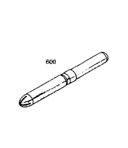
In yet another embodiment illustrated in Figure 8, the barrel 602 has a
tapered
end 690 equipped with substantially flexible petals 631 facilitating insertion
of the
tampon applicator 600 into the vaginal chamber. The number of petals may vary,
but
preferably may be 3, 4 or more, depending on the manufacturing preferences and
25 material selection. Further in this embodiment the second end 650 of the
plunger 601
is close and dome-shaped thus creating an air pressure in addition to a
mechanical
pressure during the extraction of the tampon from the barrel 602 into the
vagina
chamber. Further in this embodiment the diameter 651 at the end 650 is smaller
than
the diameter 641 at the end 640.
30 In still another embodiment illustrated in Figure 9, the mating member
760 of
the plunger 701 is raised and not depressed (see Figure 9E). Thus the diameter
760 is
larger than the diameter 741 while smaller than the diameter 751. Further, the
mating
member 730 of the barrel 702, in this embodiment, is a plurality of recesses
731, best
CA 02823792 2013-07-04
WO 2012/092671
PCT/CA2012/000015
- 11 -
illustrated in Figure 9F. The mating of the plunger 701 and the barrel 702 is
best
illustrated in figure 9D. The number of recesses may vary but preferably can
be 2, 3,
4 or more and the form of those recesses 731 can be rounded, triangular or
irregular
as per manufacturing preferences.
5 The embodiment illustrated
in Figure 10 is similar to the one at Figure 9, the
main difference is that the mating member 830 of the barrel 802 grips the
outer wall
of the plunger 801 (see figure 10D) with recesses 831.
All the features illustrated in the provided figures are exemplary and can be
interchanged between the embodiments without departing from the scope of the
10 invention. For example the
embodiments in Figure 9 of 10 may have same leaflets as
in the Figure 8 and soon.
Dissolution study.
The following is a detailed description of a preferred embodiment of the
15 tampon applicator undergoing a dissolution study.
Two different methods were used to determine disintegration:
1. Using a USP DT (Disintegration Test) Apparatus at 25C
The DT apparatus consists of a basket, rack assembly and a
mechanical device to move it up and down. A rigid basket-rack
20 assembly supporting three
cylindrical glass tubes about 106 mm long,
about 32.5 mm in internal diameter and about 3 mm thick, attached to
a mechanical device, which in turn raised and lowered the basket
smoothly at a constant frequency of between 28 and 32 cycles per
minute through a distance of 50 to 60 mm. The tampon applicator was
25 inserted in to the basket
and the dissolution test was conducted.
Results are depicted below.
2. Disintegration Test Using Magnetic Stirrer Method
This test incorporated a 100 ml glass beaker, magnetic stirrer and
magnetic stirrer unit, thermometer, stopwatch, tampon applicator and
30 distilled water.
800 ml of distilled water was placed in the beaker and the temperature
of the water was maintained at 25 +1- 1 C. The magnetic stirrer was
placed in the beaker. The magnetic stirrer unit was turned on and the
CA 02823792 2013-07-04
WO 2012/092671
PCT/CA2012/000015
- 12 -
speed was set in order to have a water vortex of 25+1- 5 mm (1" +/-
'A"), The tampon applicator was placed in the beaker and
simultaneously the stopwatch was switched on until 90% of the
tampon applicator was dissolved. Thereupon the stopwatch was
switched off On average, 90% of the tampon applicator was dissolved
between about 38 to about 43 minutes. The remaining 10% dissolved
within about 120 minutes from initiating each study.
Comparison of DT time
Sample No. DT time (minutes: seconds)
Magnetic stirrer method USP apparatus
1 46:18 37:41
2 50:14 38:33
3 43:42 38:55
Average 46:44 38:23
The following is a detailed description of a preferred embodiment of the
dipping process used to manufacture the tampon applicator of the present
invention.
The stainless steel pins are dipped into the solution and slowly withdrawn to
ensure an even distribution of the raw material. The depth of the dip will be
in the
range of 4-6 ram from the eventual cut line of the applicator.
The pins are then flipped 360 degrees in a circular manner to further ensure
even distribution of the tilm.
With the dome of the pins facing upwards, the pins will now go through a
drying phase where the removal of moisture from the film is enhanced by the
addition
of warm dry air.
The timing of this process is in the range of about 30-60 minutes and the
moisture level in the film is in the range of 3-7%.
While the foregoing provides a detailed description of a preferred embodiment
of the invention, it is to be understood that this description is illustrative
only of the
principles of the invention and not !imitative. Furthermore, as many changes
can be
made to the invention without departing from the scope of the invention, it is
intended
that all material contained herein be interpreted as illustrative of the
invention and not
in a limiting sense.