Note: Descriptions are shown in the official language in which they were submitted.
CA 02824003 2013-08-15
Device and method for thermal treatment of fluorine-containing and noble metal-
containing_ products
The present invention relates to a device and a method for thermal treatment
of
noble metal-containing products which also contain fluorine aside from noble
metals.
Various methods have become established for recovering noble metals from noble
metal-containing products, such as, for example, catalysts or fuel cells. In
the
hydrometallurgical method, the noble metal-containing layer of catalysts is
dissolved off the ceramic support by means of strong acids or bases.
Subsequently,
the noble metals are separated from the solution, for example through
precipitation
reaction.
In the pyrometallurgical method, the separation of noble metals proceeds
through
melting the noble metal-containing products in a metallurgical process. The
ceramic
fraction is transferred in a slag phase and tapped, the noble metals are
alloyed into
a collector metal, which is then also tapped and processed further.
The direct incineration of noble metal-containing sludges and multi-element
waste
materials, as described in DE 31 34 733 C2 and WO 99/037823, is also known.
The
noble metal-containing ash thus obtained is then leached in order to recover
the
noble metals.
In thermal reprocessing, noble metal-containing products that also contain
fluorine
aside from the noble metals have proven to be a problem. Thermal treatment of
these products produces hydrogen fluoride gas, HF. Said gas reacts with water
in
the ambient air to produce hydrofluoric acid.
Conventional thermal reprocessing plants, in particular ashing plants,
comprise a
thermal treatment chamber and an exhaust gas purification system. The thermal
treatment chamber is a component of a furnace and is provided with an
insulating
1
CA 02824003 2013-08-15
lining made, for example, of fireclay bricks or a ramming mass. These differ
in
composition. However, all insulating linings comprise, inter alia, silicon
dioxide Si02
(glass) and calcium oxide CaO. These components are attacked even by small
amounts of the hydrofluoric acid and hydrogen fluoride that are generated and
thus
are dissolved out of the insulating lining which reduces the service life of
the furnace
and thus of the plant.
Another problem related to hydrogen fluoride gas is the condensation of
hydrofluoric
acid at the supporting external steel shells. These are the shaping and
mechanical
load-bearing framework of the components of an ashing plant. Hydrogen fluoride
gas can diffuse through pores in the insulating lining and, in the region of
the steel
shells, react with water from the ambient air to produce hydrofluoric acid.
Condensation of hydrofluoric acid on the steel shells causes them to corrode
which
can render the entire plant unstable.
A method, in which the generation of HF is to be prevented, is disclosed in EP
1 478
042 Al. In this method, components of fuel elements and catalysts are mixed
with
inorganic additives. In the subsequent thermal treatment process, the hydrogen
fluorides and other fluorine compounds are absorbed and chemically bound by
the
additive. For this purpose, an up to 100-fold excess of the additive is added
to the
hydrogen fluoride gas that is being generated. However, it has been evident
that
the absorption at the additive is insufficient or too slow in the case of
materials
releasing hydrogen fluoride already at low temperatures allowing some hydrogen
fluoride gas to escape. Moreover, the additive occupies a fraction of the
volume of
the incineration space such that the quantity of material that can be
processed is
reduced.
It is therefore the object of the present invention to provide a plant for
thermal
reprocessing of noble metal-containing products that contain fluorine in
addition to
noble metals. The plant according to the invention shall allow all fluorine-
containing
products to be reprocessed, regardless of the volatility of the materials
contained
therein.
2
CA 02824003 2013-08-15
Another object of the present invention is to provide a method for enriching
noble
metals from fluorine-containing materials.
A first embodiment meets the object on which the present invention is based
through an ashing plant for enriching noble metals from fluorine-containing
materials, comprising a thermal treatment chamber (1) having a refractory
insulating lining on the inside of the thermal treatment chamber (1) and an
exhaust
gas cleaning system,
whereby the refractory insulating lining is resistant to hydrofluoric acid and
the
exhaust gas cleaning system comprises at least one or more acid scrubber(s)
(3, 4)
and at least one alkaline scrubber (5).
Another subject matter of the present invention is an ashing plant for
enriching
noble metals from fluorine-containing materials, comprising a thermal
treatment
chamber (1) having a refractory insulating lining on the inside of the thermal
treatment chamber (1) and an exhaust gas cleaning system,
whereby the refractory insulating lining has an aluminium oxide content of 85
% by
weight or more and the exhaust gas cleaning system comprises at least one or
more
acid scrubber(s) (3, 4) and at least one alkaline scrubber (5).
Moreover, the exhaust gas cleaning system according to the invention
preferably
comprises at least one or more thermal after-incineration chambers (2).
Preferably,
the exhaust gas cleaning system comprises one after-incineration chamber (2).
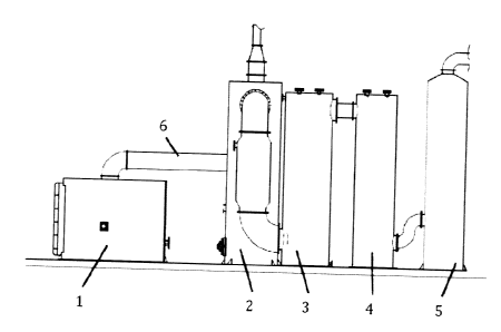
Fig. 1 shows a schematic view of an ashing plant according to the invention.
The
figure shows a preferred embodiment that comprises two acid scrubbers (3, 4).
The thermal treatment chamber (1) is a component of a furnace, into which the
materials to be processed are introduced. For this purpose, the thermal
treatment
chamber (1) comprises an opening for introduction of the corresponding
materials.
According to the invention, the thermal treatment chamber (1) can be operated
with a sub-stoichiometric amount or with an excess of air. The inside of the
thermal
3
CA 02824003 2013-08-15
treatment chamber (1) can comprise devices for incineration of the fluorine-
containing and noble metal-containing materials. This concerns, for example,
grates
for accommodation of troughs for incineration of solid materials. Liquid
materials
can be introduced into the thermal treatment chamber (1) and incinerated
therein
either batch-wise in troughs or continuously by means of corresponding dosing
facilities.
The temperature on the inside of the thermal treatment chamber (1) usually is
approx. 800 C. In this context, the refractory insulating lining is designed
to be
stable at this continuous temperature. Moreover, it is also resistant to
temperature
peaks of up to approx. 2,000 C. It is feasible according to the invention to
heat the
thermal treatment chamber (1) directly or indirectly. All means of heating
known
according to the prior art are feasible, for example gas and oil heating or
electrical
heating.
According to the invention, an acid scrubber (3, 4) is a scrubbing stage, in
which
exhaust gases from the thermal treatment chamber (1) are washed with water or
with water acidified by the hydrogen fluoride gas to be washed out. According
to the
invention, an alkaline scrubber (5) is a scrubbing stage, in which the exhaust
gases
are washed with an alkaline agent.
Heating fluorine-containing materials in the thermal treatment chamber (1) in
the
ashing plant according to the invention produces exhaust gases that contain
hydrogen fluoride gas. Since the thermal treatment chamber (1) is lined with
the
hydrofluoric acid-resistant insulating lining, the chamber is not attacked by
the
exhaust gases. In the exhaust gas cleaning system according to the invention,
the
exhaust gas is initially subjected to thermal reprocessing in a thermal after-
treatment chamber (2) and then all hydrogen fluoride gas or hydrofluoric acid
already formed is removed in the acidic and alkaline scrubbing stages (3, 4,
5) such
that the exhaust gases are then harmless and can be guided to the outside, for
example by means of a chimney.
4
CA 02824003 2013-08-15
The ashing plant according to the invention can provide further cleaning
stages or
cleaning agents for exhaust gas cleaning in order to remove, for example,
soot,
chlorine or nitrous gases from the exhaust gases. Pertinent cleaning agents or
cleaning stages are described in the prior art.
According to the invention, the hydrofluoric acid-resistant insulating lining
is
resistant both to hydrogen fluoride gas and to hydrofluoric acid.
The noble metal-containing and fluorine-containing materials are placed in the
thermal treatment chamber (1). The exhaust gases produced in the thermal
treatment chamber (1) during thermal treatment can first be guided into a
thermal
after-incineration chamber (2). Preferably, said chamber is also provided with
a
hydrofluoric acid-resistant refractory insulating lining. Moreover, the ashing
plant
comprises an exhaust gas conduit (6) for guiding the exhaust gases out of the
thermal treatment chamber (1). Preferably, the inside of said exhaust gas
conduit
(6) is also provided with a hydrofluoric acid-resistant refractory insulating
lining.
Thermal treatment chamber (1), exhaust gas conduit (6), and the after-
incineration
chamber (2), which is preferably present, are the components of the ashing
plant
through which exhaust gas flows before hydrogen fluoride gas is removed from
the
exhaust gas in the acidic and alkaline scrubbers (3, 4, 5). Providing the
thermal
treatment chamber (1) as well as the after-incineration chamber (2), and the
exhaust gas conduit (6) with a hydrofluoric acid-resistant refractory
insulating lining
increases the service life of the ashing plant according to the invention,
since these
components cannot be attacked by the hydrofluoric acid or hydrogen fluoride
gas.
The refractory insulating lining of the present invention can be a ramming
mass.
Said ramming mass preferably has an aluminium oxide (A1203) content of 85 % by
weight or more, in particular of 88 Wo by weight or more. Said insulating
lining is
stable at a working temperature and at a continuous temperature of approx. 800
C. However, it also withstands peak temperatures of up to approx. 2,000 C.
CA 02824003 2013-08-15
Ramming masses usually contain silicon dioxide (SiO2) and/or calcium oxide
(CaO)
in addition to aluminium oxide. These components are also present in
conventional
refractory insulating linings. These are dissolved by hydrofluoric acid, which
destroys the insulating lining.
Surprisingly, it has been evident that an aluminium oxide fraction of 85 % by
weight
or more, in particular of 88 % by weight or more, being present in a ramming
mass
is sufficient to provide hydrofluoric acid resistance. The ramming masses
according
to the invention can also contain different fractions of calcium oxide and
silicon
dioxide as further components in addition to aluminium oxide. Despite the
calcium
oxide and/or silicon dioxide fraction of the ramming mass being up to 15 % by
weight, in particular up to 12 % by weight, the ramming mass is not attacked
by
hydrofluoric acid. In this context, the relative content of calcium oxide
and/or silicon
oxide or their ratio with respect to each other is irrelevant. Moreover, the
corresponding ramming mass is easy to process and easily adapts to the
internal
wall of the thermal treatment chamber (1), exhaust gas conduit (6), and after-
incineration chamber (2).
In this context, it is feasible according to the invention that the thermal
treatment
chamber (1), the after-incineration chamber (2), and the exhaust gas conduit
(6)
comprise the same or different insulating lining(s).
Preferably, the thermal treatment chamber (1), the after-incineration chamber
(2)
and/or the exhaust gas conduit (6) further comprise an external lining. The
external
lining can be provided using materials that are known according to the prior
art.
Preferably, the external lining is a mineral fibre. The external insulation is
surrounded by a steel plate. The steel plate fixes the external insulation in
place and
serves for stabilisation and shaping of the components of the ashing plant.
One problem during the incineration of fluorine-containing products is the
generation of hydrofluoric acid that causes corrosion in the region of the
supporting
external steel shells. If hydrogen fluoride gas HF diffuses through pores to
reach the
6
CA 02824003 2013-08-15
space behind the temperature-resistant insulating lining in the reaction
space, it
reaches the external steel constructs part of which are load-bearing. Hydrogen
fluoride gas can react with water from the ambient air to form hydrofluoric
acid in
this location. Hydrofluoric acid forms an azeotropic mixture with water at a
concentration of 38.2 % HF, whereby the boiling temperature of the azeotropic
mixture is 112 C. If hydrofluoric acid condenses at the steel walls, it
causes these
to corrode.
The effect of having the external insulation is that the temperature at the
steel
shell, i.e. at the external steel wall of the plant components, does not drop
below
120 C. In this context, the thickness of the external insulation is a
function of the
temperature profile on the inside of the corresponding component of the ashing
plant. Condensation of hydrofluoric acid does not take place at a temperature
of 120
C. Accordingly, if hydrogen fluoride gas were to diffuse through the
refractory
insulating lining towards the outside, no corrosion damage to load-bearing
steel
constructs is to be expected.
According to the invention, the thickness of the insulation on the thermal
treatment
chamber (1), exhaust gas conduit (6), and after-incineration chamber (2) can
differ.
However, it is feasible just as well that the insulation of all components is
equal in
thickness. Accordingly, thermal treatment chamber (1), exhaust gas conduit
(6),
and after-incineration chamber (2) can, for example, comprise an external
insulation made of a mineral fibre at a thickness of approx. 10 cm.
In a preferred embodiment, the thermal treatment chamber (1) comprises a
refractory insulating lining on the inside, whereby the thickness of the wall
of the
chamber plus the insulating lining is approx. 30 cm, and an external
insulation with
a thickness of approx. 10 cm.
According to the invention, the ashing plant preferably comprises at least one
scrubber made of graphite (3) with a double-walled design. Said double-walled
scrubber (3) preferably comprises a cooling system, in particular a water
cooling
7
CA 02824003 2013-08-15
system. The scrubber (3) can comprise a steel plate as external shell. The
double-
walled scrubber (3) comprises valves for feeding and discharging the coolant.
The coolant, for example water, flows between the external graphite wall and
the
external shell. This leads to indirect dissipation of heat from the exhaust
gas via the
scrubbing medium and the graphite walls.
Water has proven to be particularly well-suited as coolant. Water is
inexpensive and
easy to handle. Moreover, if there was any exposure to the exhaust gases,
there
would be no hazard of undesired chemical reactions occurring.
The thickness of the graphite walls preferably is in the range of 3 cm to 4
cm. It has
been evident that this thickness is sufficient to maintain sufficient
temperature and
acid stability.
Water flows into the double-walled scrubber (3) as scrubbing agent for the
exhaust
gas. The water reacts with hydrogen fluoride gas HF in the exhaust gas and
removes it by scrubbing. The scrubbing water containing the hydrogen fluoride
gas
in the form of a salt is then collected and subjected to disposal.
Graphite is characterised not only by acid resistance, but by high temperature
resistance as well. The exhaust gases flow from the thermal after-incineration
chamber (2) or the thermal treatment chamber (1) into an acid scrubber. The
temperature of said exhaust gases is up to 1,000 C. It has been evident that
the
temperature resistance of graphite is sufficient in this context.
Preferably, the exhaust gas cleaning system according to the invention further
comprises at least one single-walled scrubber (4) made of graphite. This
scrubber
also comprises a steel plate for its external shell. Preferably, the thickness
of the
graphite wall is in the range of 3 cm to 4 cm.
8
CA 02824003 2013-08-15
In a preferred embodiment, the exhaust gas cleaning system comprises a double-
walled scrubber made of graphite (3) and a single-walled scrubber made of
graphite
(4). This embodiment is shown in Fig. 1. Both acid scrubbers (3, 4) are
cylindrical in
shape in this preferred embodiment and have an internal diameter of more than
1
m. The exhaust gas contacts the scrubbing water over the entire height of
approx. 4
m or more and is cleaned in the process. The scrubbing water usually flows
into the
scrubber from above such that the exhaust gas is washed with water in the
upper
region of the scrubber. In the process, it becomes enriched in hydrogen
fluoride gas
to the effect that the exhaust gas is washed with an acid, namely water
containing a
hydrofluoric acid fraction, in the lower region. In this context, the terms,
upper and
lower, refer to the spatial arrangement that is also shown in Fig. 1.
In the first double-walled scrubber (3), at least a majority or all of the
hydrogen
fluoride gas is washed out of the exhaust gas with water. Moreover, the
exhaust gas
is also being cooled. In the second single-walled scrubber (4), hydrogen
fluoride gas
that may still be present is bound and thus removed from the exhaust gas. No
further cooling of the exhaust gases is needed.
The ashing plant of the present invention further comprises an alkaline
scrubber
(5). The exhaust gases are guided from the at least one acid scrubber (3, 4)
into
said alkaline scrubber after most or all of the hydrogen fluoride has has been
removed. The alkaline scrubber (5) can comprise a coating on its inside that
is
resistant to alkaline scrubbing water and any traces of hydrogen fluoride gas
that
may still be present in the exhaust gas. Specifically, the coating is stable
when
exposed to bases having a pH of at least 10 or more, in particular of at least
11 or
more. Preferably, the alkaline scrubber (5) comprises on its inside a coating
made
of a plastic material, in particular made of polypropylene. The external shell
of the
alkaline scrubber can consist of steel.
A plastic coating has proven to be easy to handle. The lining is made to be
homogeneous and is not associated with a risk of cracks. Moreover, plastic
materials, in particular polypropylene, are resistant to alkaline scrubbing
water as is
9
CA 02824003 2013-08-15
used in this scrubbing stage. If any residual HF were still to be present at
this stage,
the coating would not be attacked by it.
The exhaust gas guided into the alkaline scrubber (5) is largely free of
hydrogen
fluoride gas. However, it cannot be excluded that some traces of hydrogen
fluoride
gas may still be present. If the alkaline scrubber (5) were lined with the
otherwise
common glass fibre-reinforced plastic materials (GFR), these residual amounts
of
hydrogen fluoride gas would be sufficient to attack and quickly etch away the
glass
fibres in the plastic material. The internal lining would have to be replaced
after just
a short time under these conditions.
The ashing plant according to the invention can further comprise a control
unit. The
control unit controls the temperature profiles needed during the thermal
treatment
depending on the specific material and also controls the exhaust air line as a
function of negative pressure, temperature, and oxygen content of the exhaust
gas.
As a matter of principle, both continuous and discontinuous operation are
feasible. A
discontinuous operation is preferred.
In a further embodiment, the present invention comprises a method for
enriching
noble metals from fluorine-containing materials, comprising a thermal
treatment of
the materials in a thermal treatment chamber (1) having a hydrofluoric acid-
resistant refractory insulating lining and cleaning of the exhaust gases
generated
during the thermal treatment, whereby the cleaning comprises the following
steps in
the following order:
a) if applicable, thermal after-incineration in an after-incineration chamber
(2),
b) scrubbing of the exhaust gases with water and/or an acid, and
c) scrubbing of the exhaust gases with a base.
A noble metal-containing ash is generated during the thermal treatment of the
noble metal-containing and fluorine-containing materials. Said ash is then
reprocessed according to wet chemical methods known according to the prior art
in
'
CA 02824003 2013-08-15
order to recover the noble metals it contains. In the scope of the present
invention,
noble metals are gold, silver, and the metals of the platinum group.
The thermal treatment usually proceeds at a temperature of up to 800 C. Peak
temperatures of up to approx. 2,000 C may occur briefly. Following the
introduction of the materials into the thermal treatment chamber (1), the
temperature is increased slowly up to a temperature of approx. 600 C to 800
C.
The specific temperature depends on the materials to be processed.
The exhaust gases generated during the thermal treatment are first subjected
to
thermal after-incineration in an after-incineration chamber (2), if
applicable.
Subsequently, the exhaust gases are washed with water or an acid in an acid
scrubber. According to the invention, water is used as the scrubbing agent.
Water
washes hydrogen fluoride gas out of the exhaust gas. This produces an acid,
which
washes out more hydrogen fluoride gas such that, in the course of the entire
scrubbing process, both water and an acid wash the exhaust gases.
The scrubbing water can have room temperature in this context. However, it is
feasible just as well that the scrubbing water has a temperature that is
slightly
higher than room temperature. In this context, the temperature should not be
more
than 10 to 20 C above ambient temperature.
The salt-enriched scrubbing water obtained in step b) of the scrubbing process
can
be fed to a waste water treatment plant periodically or continuously as side
stream.
Preferably, scrubbing of the exhaust gases with water and/or an acid comprises
two
steps, namely
bl) scrubbing and simultaneous cooling of the exhaust gases in a double-walled
graphite scrubber (3) followed by
b2) scrubbing of the exhaust gases in a single-walled graphite scrubber (4).
11
CA 02824003 2013-08-15
It is preferred to cool the exhaust gas in the double-walled graphite scrubber
(3) by
means of a cooling system, in particular a water cooling system. Provided
water is
used as coolant, the temperature of the water preferably is approx. 60 C.
Hydrogen fluoride gas is removed from the exhaust gas by introducing water
into
the inside of the double-walled scrubber (3).
In order to ensure that the hydrogen fluoride gas is removed from the exhaust
gas
as close to completely as possible, the exhaust gas is washed twice with water
and/or an acid in a preferred embodiment and, for this purpose, is guided from
the
first double-walled graphite scrubber (3) into a second single-walled graphite
scrubber (4). The exhaust gas is washed with water and/or an acid in both
scrubbers (3, 4). In both scrubbing stages, the initial scrubbing agent is
water. The
water becomes acidified by the hydrogen fluoride gas washed out of the exhaust
gas such that, overall, both water and an acid wash the exhaust gas at the
respective stages. If the hydrogen fluoride gas is already removed completely
from
the exhaust gas in the first stage, the second stage entails a cleaning with
water
only.
In scrubbing step c), the exhaust gas is neutralised and acidic components
originating from step b) are removed. A base with a pH of at least 10 or more,
in
particular of at least 11 or more, can be used as base in this context. It is
preferred
to use sodium hydroxide solution for scrubbing the exhaust gases in step c).
Sodium
hydroxide solution does not undergo any undesired reaction with the exhaust
gas
components. Moreover, it is inexpensive and easy to handle.
The method according to the invention is suitable preferably for the
processing of
materials that have a fluorine content of up to 5 Wo by weight. It is
preferred to use
fluoro-organic materials, PTFE films, fuel cells, catalysts and/or pastes as
materials
to be subjected to the thermal treatment. As a matter of principle, the method
is
suitable for all materials having a fluorine content of up to 5 % by weight
that
decompose at a temperature of approx. 800 C, in particular of approx. 600 C.
12
CA 02824003 2013-08-15
It is preferred to implement the method according to the invention in an
ashing
plant of the type described above. The ashing plant according to the invention
is
suitable for the use and implementation of the method according to the
invention.
13
CA 02824003 2013-08-15
List of reference numbers
1 Thermal treatment chamber
2 After-incineration chamber
3 Double-walled graphite scrubber
4 Single-walled graphite scrubber
Alkaline scrubber
6 Exhaust gas conduit
14