Note: Descriptions are shown in the official language in which they were submitted.
CA 02824131 2013-08-21
50922
SEED INDUCTOR FOR AN AGRICULTURAL IMPLEMENT
HAVING AN ADJUSTABLE AIR BYPASS
BACKGROUND
[0001] The invention
relates generally to ground working equipment, such as
agricultural equipment, and more specifically, to an inductor box for a
pneumatic
distribution system of an agricultural implement.
[0002] Generally,
planting implements (e.g., planters) are towed behind a tractor
or other work vehicle via a mounting bracket secured to a rigid frame of the
implement. These planting
implements typically include multiple row units
distributed across the width of the implement. Each row unit is configured to
deposit
seeds at a desired depth beneath the soil surface, thereby establishing rows
of planted
seeds. For example, each row unit may include a ground engaging tool or opener
(e.g., an opener disc) that forms a seeding path for seed deposition into the
soil. In
certain configurations, a gauge wheel is positioned a vertical distance above
the
opener to establish a desired trench depth for seed deposition into the soil.
As the
implement travels across a field, the opener excavates a trench into the soil,
and seeds
are deposited into the trench. In certain row units, the opener is followed by
a packer
wheel that packs the soil on top of the deposited seeds.
[0003] Certain
planting implements include a remote seed tank, and a pneumatic
distribution system configured to convey seeds from the tank to each row unit.
For
example, the pneumatic distribution system may include an inductor box
positioned
beneath the seed tank. The inductor box is configured to receive seeds from
the tank,
to fluidize the seeds into an air/seed mixture, and to distribute the air/seed
mixture to
the row units via a network of pneumatic hoses/conduits. Each row unit, in
turn,
receives the seeds from the pneumatic hoses/conduits, and directs the seeds to
a
metering system. The metering system is configured to provide a flow of seeds
to a
seed tube for deposition into the soil. By operating the metering system at a
particular
speed, a desired seed spacing may be established as the implement traverses a
field.
CA 02824131 2013-08-21
50922
BRIEF DESCRIPTION
[0004] In one embodiment, a particulate material delivery system for an
agricultural implement including, an inductor box configured to receive
particulate
material from a tank, the inductor box including, an inductor segment
comprising an
air bypass channel extending through a particulate material supply chamber,
wherein
the particulate material supply chamber is configured to receive the
particulate
material for distribution to at least one row unit, and the air bypass channel
is
configured to guide airflow through the particulate material supply chamber
without
interacting with a flow of the particulate material through the particulate
material
supply chamber, and an airflow control device in communication with the
inductor
segment and configured to control the airflow through the air bypass channel.
[0005] In another embodiment, a particulate material delivery system for an
agricultural implement including, an inductor box including, a particulate
material
supply chamber configured to receive particulate material from a particulate
material
source, an air supply chamber configured to receive airflow from an airflow
supply
for use in conveying particulate material through the inductor box, and an air
bypass
channel configured to guide airflow from the air supply chamber through the
particulate material supply chamber without interacting with a flow of the
particulate
material through the particulate material supply chamber, and an airflow
control
device configured to control the airflow through the air bypass channel.
[0006] In a further embodiment, a particulate material delivery system for
an
agricultural implement including, an inductor segment including, a particulate
material supply chamber configured to receive particulate material from a
particulate
material tank and a first airflow from an air source, a particulate material
delivery
chamber configured to receive the particulate material from the particulate
material
fluidization chamber and to distribute the particulate material to at least
one row unit,
an air bypass channel extending through the particulate material supply
chamber and
configured to direct a second airflow through the particulate material supply
chamber
and into the particulate material delivery chamber without interacting with
the
2
CA 02824131 2013-08-21
50922
particulate material in the particulate material supply chamber, and an
airflow control
device configured to control the airflow through the air bypass channel.
DRAWINGS
[0007] These and other features, aspects, and advantages of the present
invention
will become better understood when the following detailed description is read
with
reference to the accompanying drawings in which like characters represent like
parts
throughout the drawings, wherein:
[0008] FIG. 1 is a perspective view of an embodiment of an agricultural
implement
configured to deposit particulate material into a soil surface;
[0009] FIG. 2 is a perspective view of an embodiment of a particulate
material
tank coupled to an inductor box;
[0010] FIG. 3 is a perspective view of an embodiment of an inductor box;
[0011] FIG. 4 is a cross-sectional side view of an embodiment of an
inductor box;
[0012] FIG. 5 is a cross-sectional rear view of an embodiment of an
inductor box;
[0013] FIG. 6 is a cross-sectional rear view of an embodiment of an
inductor box
with an airflow control device;
[0014] FIG. 7 is a front view of an embodiment of an airflow control
device;
[0015] FIG. 8 is a front view of another embodiment of an airflow control
device;
[0016] FIG. 9 is a front view of another embodiment of an airflow control
device;
[0017] FIG. 10 is a cross-sectional side view of the airflow control device
of FIG.
9, taken along line 1 0- 1 0;
[0018] FIG. 11 is a front view of an embodiment of an airflow control
device
within an air bypass channel; and
3
CA 02824131 2013-08-21
50922
[0019] FIG. 12 is a front view of another embodiment of an airflow control
device.
DETAILED DESCRIPTION
[0020] One or more specific embodiments of the present invention will be
described below. In an effort to provide a concise description of these
embodiments,
all features of an actual implementation may not be described in the
specification. It
should be appreciated that in the development of any such actual
implementation, as
in any engineering or design project, numerous implementation-specific
decisions
must be made to achieve the developers' specific goals, such as compliance
with
system-related and business-related constraints, which may vary from one
implementation to another. Moreover, it should be appreciated that such a
development effort might be complex and time consuming, but would nevertheless
be
a routine undertaking of design, fabrication, and manufacture for those of
ordinary
skill having the benefit of this disclosure.
[0021] When introducing elements of various embodiments of the present
invention, the articles "a," "an," "the," and "said" are intended to mean that
there are
one or more of the elements. The terms "comprising," "including," and "having"
are
intended to be inclusive and mean that there may be additional elements other
than the
listed elements.
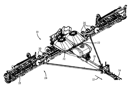
[0022] FIG. 1 is a perspective view of an embodiment of an agricultural
implement
configured to deposit particulate material into a soil surface. In the
illustrated
embodiment, the implement 10 is configured to be towed along a direction of
travel
12 by a work vehicle, such as a tractor or other prime mover. The work vehicle
may
be coupled to the implement 10 by a hitch assembly 14. As illustrated, the
hitch
assembly 14 is coupled to a main frame assembly 16 of the implement 10 to
facilitate
towing of the implement 10 in the direction of travel 12. In the illustrated
embodiment, the frame assembly 16 is coupled to a tool bar 18 that supports
multiple
row units 20. Each row unit 20 is configured to deposit particulate material
(e.g.,
seeds) at a desired depth beneath the soil surface, thereby establishing rows
of planted
seeds. The implement 10 also includes particulate material tanks 22, and a
pneumatic
4
CA 02824131 2013-08-21
50922
distribution system 24 configured to convey particulate material from the
tanks to the
row units 20. In certain embodiments, the pneumatic distribution system
includes an
inductor box positioned beneath each particulate material tank 22. Each
inductor box
is configured to receive particulate material from a respective tank, to
fluidize the
particulate material into an air-particulate material mixture, and to
distribute the air-
particulate material mixture to the row units 20 via a network of pneumatic
hoses/conduits (i.e., the pneumatic distribution system 24).
[0023] In certain embodiments, each row unit 20 includes a residue manager,
an
opening assembly, a particulate material tube, closing discs, and a press
wheel. The
residue manager includes a rotating wheel having multiple tillage points or
fingers
that break up crop residue, thereby preparing the soil for particulate
material
deposition. The opening assembly includes a gauge wheel and an opener disc.
The
gauge wheel may be positioned a vertical distance above the opener disc to
establish a
desired trench depth for particulate material deposition into the soil. As the
row unit
travels across a field, the opener disc excavates a trench into the soil for
particulate
material deposition. The particulate material tube, which may be positioned
behind
the opening assembly, directs a particulate material from a metering system
into the
excavated trench. The closing discs then direct the excavated soil into the
trench to
cover the planted particulate material. Finally, the press wheel packs the
soil on top
of the particulate material with a desired pressure.
[0024] While the illustrated implement 10 includes 24 row units 20, it
should be
appreciated that alternative implements may include more or fewer row units
20. For
example, certain implements 10 may include 6, 8, 12, 16, 24, 32, or 36 row
units, or
more. In addition, the spacing between row units may be particularly selected
based
on the type of crop being planting. For example, the row units may be spaced
30
inches from one another for planting corn, and 15 inches from one another for
planting soy beans.
[0025] As mentioned above, the pneumatic distribution system 24 includes an
inductor box configured to receive particulate material (e.g., seeds) from a
respective
tank. Depending on the desired application, the pneumatic distribution system
may
CA 02824131 2013-08-21
50922
distribute a wide variety of seeds (e.g., light seeds, heavy seeds, large
seeds, small
seeds, etc). The inductor box fluidizes the particulate material from the tank
22 into
an air-particulate material mixture for distribution to the row units 20
through a
network of pneumatic hoses/conduits. As illustrated in FIG. I, the row units
20 are
positioned at different distances from the tanks 22. The varying distances
between the
row units 20 and the tanks 22 varies the flow of particulate material through
the
pneumatic distribution system 24. For example, the flow path may be shorter
for row
units near the inductor box, and larger for row units farther from the
inductor box.
Accordingly, the pneumatic distribution system 24 may include an airflow
control
device(s) to control particulate material flow through the inductor box. By
controlling
the airflow through the inductor box, the airflow control device(s)
establishes a
desired particulate material flow to each of the row units 20, thereby
reducing the
possibility of starvation and/or overfilling of the row units.
[0026] FIG. 2 is a
perspective view of an embodiment of a particulate material
tank 22 coupled to an inductor box 40. The particulate material tank 22
includes an
opening 38 for receiving particulate material (e.g., seeds, etc.) for storage
in the tank
22. The tank 22 secures the particulate material inside using a lid 42 that
selectively
covers the opening 38. The lid 42 securely attaches to the tank 22 with
multiple
fasteners 44. On the opposite side of the tank 22 from the lid is the inductor
box 40.
The inductor box 40 attaches to the bottom of the tank 22 and receives gravity
fed
particulate material for fluidization. The inductor box 40 includes a housing
46 that is
coupled to the tank 22 with bolts 48. Moreover, the inductor box 40 includes
an air
supply port 50, and multiple inductor segments 52. It is through the air
supply port 50
that the inductor box 40 receives airflow from an air supply (e.g., a fan, a
blower,
etc.). The airflow from the air supply enables the inductor box 40 to fluidize
the
particulate material and to pressurize the tank 22. In some embodiments, the
tank 22
may be made of a flexible material that expands when pressurized with airflow
from
the air supply. As will be explained in greater detail below, the inductor box
40
controls airflow from the air supply into a series of air pathways with an air
control
device(s). The airflow control device(s) controls particulate material flow
from the
6
CA 02824131 2013-08-21
50922
inductor segments 52 to the row units 20, thus reducing overfilling or
underfilling the
row units 20.
[0027] FIG. 3 is a perspective view of an embodiment of an inductor box 40.
As
illustrated, the inductor box 40 includes multiple inductor segments 52
disposed
within a chamber 60 formed by the inductor box housing 46. In the illustrated
embodiment, there are eight inductor segments 52. However, other embodiments
may
include a different number of inductor segments 52 (e.g., 1, 2, 3, 4, 5, 6, 7,
8,9, 10, or
more). As mentioned above, the particulate material enters the inductor
segments 52
from the tank and the particulate material is fluidized (i.e., mixed with
air). Once the
particulate material is fluidized, the air-particulate material mixture exits
the inductor
box 40 through particulate material delivery ports 62 in the inductor segments
52.
[0028] FIG. 4 is a cross-sectional side view of an embodiment of an
inductor box
40 coupled to the tank 22. As illustrated, the inductor box 40 is coupled to
the tank 22
with bolts 48. The inductor box 40 surrounds a particulate material outlet(s)
66 of the
tank 22, thereby enabling particulate material to exit the tank 22 and enter
the
inductor box 40. More specifically, as the particulate material exits the tank
22, in a
direction 68, the particulate material enters the inductor segment(s) 52. As
explained
above, the inductor box 40 includes an inductor segment 52 disposed within the
inductor box chamber 60. The top of the inductor segment 52 includes two
surfaces
70 and 72. The surfaces 70 and 72 may be angled to facilitate flow of
particulate
material into the inductor segment 52. As particulate material travels through
the
inductor segment 52, the particulate material passes through a series of
chambers
before exiting through the particulate material delivery port 62. The chambers
in the
inductor segment 52 include a particulate material supply chamber 74, a
fluidization
chamber 76, and a particulate material delivery chamber 78.
[0029] The angled surfaces 70 and 72 channel the particulate material from
the
tank 22 into the particulate material supply chamber 74 through a particulate
material
supply chamber inlet 80. The particulate material supply chamber 74 guides the
particulate material from the particulate material supply chamber inlet 80 to
the
particulate material supply chamber outlet 86 via a first wall 82 and a second
wall 84.
7
CA 02824131 2013-08-21
50922
,
As illustrated, the walls 82 and 84 include respective vertical portions 88
and 90, as
well as respective angled portions 92 and 94. As the particulate material
flows
through the particulate material supply chamber 74, the angled portions 92 and
94 of
the walls 82 and 84 direct the particulate material toward the particulate
material
supply chamber outlet 86 at a base 96 of the inductor box 40.
[0030] Airflow from the air supply then conveys the particulate material
through
the particulate material supply chamber outlet 86 and into the fluidization
chamber
76. The fluidization chamber 76 includes a first wall 98 and shares the second
wall
84 of the particulate material supply chamber 74. In order to fluidize the
particulate
material, the fluidization chamber 76 creates a vortex 100 between the walls
98 and
84. The vortex 100 separates and mixes the particulate material with the
airflow (i.e.,
the vortex 100 enables the particulate material to fluidize) before the
particulate
material flows to the particulate material delivery chamber 78. When the
airflow
through fluidization chamber 76 reaches a sufficient level the particulate
material is
carried out of the fluidization chamber 76 and into the particulate material
delivery
chamber 78. At that point more particulate material is allowed to flow into
the
fluidization chamber 76. In the particulate material delivery chamber 78,
airflow
from an air bypass channel 102 and airflow from the fluidization chamber 76
conveys
the particulate material out of the particulate material delivery chamber 78,
through
the particulate material delivery port 62, and to the row units 20. In some
embodiments, the inductor box 40 includes an airflow control device 104 that
controls
the particulate material flow through the inductor segment 52. In the present
embodiment, the airflow control device 104 is a baffle. However, in other
embodiments, the airflow control device 104 may be a plug. As illustrated, the
airflow control device 104 may couple to the inductor segment 52 with
retention
features 106. As will be explained in more detail below, the airflow control
device
104 may control airflow through each of the air bypass channels 102, and thus
the
flow of particulate material out of each inductor segment 52.
[0031] As explained above, the inductor box 40 includes the air supply port
50 for
receiving airflow from an air supply that pressurizes the tank 22 and conveys
particulate material through the inductor segment 52. The airflow from the air
supply
8
CA 02824131 2013-08-21
50922
,
passes through the air supply port 50 and enters an air supply chamber 108.
The air
supply chamber 108 extends through the inductor box 40 in a generally
perpendicular
direction to the flow path through the inductor segments 52, thereby supplying
each
inductor segment 52 with airflow.
100321 The air supply chamber 108 divides the airflow from the air supply
into
four airflow paths numbered 110, 112, 114, and 116. The first airflow path 110
passes through the first screen 64 and enters the particulate material supply
chamber
74. As the airflow through the first airflow path 110 enters the particulate
material
supply chamber 74, the airflow engages the particulate material and urges the
particulate material in the direction 68. For example, when using light
particulate
material (e.g., sunflower seeds, sweet corn seeds), the airflow through the
airflow path
110 reduces blockage of the particulate material supply chamber 74 by
providing
additional force (in addition to gravity) to move the particulate material
through the
particulate material supply chamber 74.
[00331 While the airflow through the first airflow path 110 facilitates
urging the
particulate material in the direction 68 through the particulate material
supply
chamber 74, the airflow through the second airflow path 112 conveys the
particulate
material out of the particulate material supply chamber 74 and into the
fluidization
chamber 76. The airflow through the second airflow path 112 flows through a
second
screen 118. The second screen 118 is coupled to the first wall 82 and to the
base 96
of the inductor box 40. The second screen 118, like the first screen 64,
blocks the
particulate material from entering the air supply chamber 108.
100341 A third airflow path 114 flows through the first screen 64 and into
the tank
22. The airflow in the third airflow path 114 pressurizes and expands the tank
22.
However, in some embodiments, the lid 42 may not create a fluid tight seal
with the
tank 22. Accordingly, airflow in the third airflow path 114 may provide
continuous
airflow into the tank 22 to replace pressurized air lost through leaks in the
lid 42. As
a result, airflow from the first airflow path 110 is able to flow through the
particulate
material supply chamber 74, and the airflow in the second airflow path 112 is
able to
convey the particulate material into the fluidization chamber 76. In other
words, the
9
CA 02824131 2013-08-21
50922
airflow in the third airflow path 114 pressurizes the tank 22, thus equalizing
pressure
within the system.
[0035] The airflow in the fourth airflow path 116 flows from the air supply
chamber 108 through the air bypass channel 102 and into the particulate
material
delivery chamber 78. The air bypass channel 102 is disposed within the
particulate
material supply chamber 74 and extends between the first particulate material
supply
chamber wall 82 and the second particulate material supply chamber wall 84.
The
walls 82 and 84 include respective apertures 120 and 122 that enable the
airflow of
the fourth airflow path 116 to pass through the air bypass channel 102. The
air bypass
channel 102 is oriented in a generally crosswise direction to the particulate
material
flow through the particulate material supply chamber 74 and is substantially
in line
with the particulate material delivery port 62. Moreover, the air bypass
channel 102 is
positioned above the fluidization chamber 76 to enable the airflow from the
fourth
airflow path 116 to urge the particulate material exiting the fluidization
chamber 76
into the particulate material delivery port 62 for delivery to the row units
20.
[0036] As explained above, the airflow from the air supply chamber 108 is
divided
into four airflow paths numbered 110, 112, 114, and 116. The first airflow
path 110,
second airflow path 112, and the fourth airflow path 116 flow through the
inductor
segment. The flow rate of the airflow through anyone of these three airflow
paths
(i.e., 110, 112, and 116) affects the flow rate of the airflow through the
remaining
airflow paths in the inductor segment. For example, decreasing the flow rate
of the
airflow through the fourth airflow path 116 increases the flow rate of the
airflow
through the first airflow path 110 and the second airflow path 112. As a
result, the
first airflow path 110 and the second airflow path 112 convey more particulate
material through the inductor segments 52 to the row units 20. Similarly,
increasing
the flow rate of the airflow through the fourth airflow path 116 will decrease
the
airflow flowing through the first airflow path 110 and the second airflow path
112.
The decrease in the airflow through the first airflow path 110 and the second
airflow
path 112 will reduce the particulate material movement through the inductor
segments
52 to the row units 20.
CA 02824131 2013-08-21
50922
100371 FIG. 5 is a rear cross-sectional view of an embodiment of an
inductor box
40 with multiple inductor segments 52. Each of the inductor segments 52
delivers
particulate material to one or more row units 20. In the present embodiment,
there are
eight inductor segments 52. However, different embodiments may include
different
numbers of inductor segments (e.g., 1, 2, 3, 4, 5, 6, 7, 8, 9, 10, or more
inductor
segments). In the present embodiment, the inductor box 40 does not include an
airflow control device. Accordingly, particulate material flow will be
generally equal
through each of the inductor segments 52 assuming an equal amount of
backpressure
from each of the delivery conduits (i.e., each conduit is the same length and
has the
same cross sectional area).
[0038] FIG. 6 is a rear cross-sectional view of an embodiment of an
inductor box
40 with an airflow control device 104 positioned adjacent to the air bypass
channels
102 in each of the inductor segments 52. As explained above, the row units 20
are
positioned at different distances from the inductor box 40. The varying
distances
between the row units 20 and the inductor box 40 affects the flow rate of
particulate
material through the pneumatic distribution system 24. Accordingly, by
controlling
the airflow through the inductor box, the airflow control device 104 controls
the flow
of particulate material to the row units 20, which reduces the possibility of
starvation
and/or overfilling the row units with particulate material. In the present
embodiment,
the airflow control device 104 is a baffle with multiple apertures 124. As
illustrated,
the apertures 124 differ in size. The size of the apertures 124 is selected
such that
each row unit 20 receives an approximately equal flow rate of particulate
material
from a corresponding inductor segment 52. For example, the apertures 124 in
the
flow control device 104 will be larger for inductor segments 52 that send
particulate
material to row units 20 closer to the inductor box 40. The increase in
airflow
through the air bypass channel 102 reduces the airflow through the second
airflow
path 110 and the third airflow path 112, which decreases particulate material
flow
rates through inductor segments 52 that feed the row units 20, thereby
reducing the
possibility of the row units overfilling. Likewise, the apertures 124 in the
airflow
control device 104 will be smaller for inductor segments 52 that send
particulate
material to row units 20 farther away from the inductor box 40. The decrease
in
11
CA 02824131 2013-08-21
50922
airflow through the air bypass channel 102 increases the airflow through the
second
airflow path 110 and the third airflow path 112, which increases particulate
material
flow rates through inductor segments 52 that feed the row units 20 further
away from
the inductor box 40, preventing the row units 20 from starving. In the present
embodiment, the size of the apertures 124 increase toward the center of the
air control
device 102. However, different embodiments may have a different arrangement
(e.g.,
apertures 124 that increase in size from left to right, apertures 124 that
increase in size
from right to left, apertures 124 that decrease in size from the center out,
or apertures
124 that may alternate in size across the air flow control device 104). The
aperture
sizes and arrangement depend on which inductor segments 52 feed each row unit
20
and the distance between each row unit 20 and the inductor box 40.
[0039] FIG. 7 is a front view of an embodiment of an airflow control device
104.
In the present embodiment, the airflow control device 104 is a baffle 130. The
baffle
130 restricts airflow through a single inductor segment 52. The baffle 130
includes a
circular aperture 132 that enables airflow to pass through the baffle 130 and
into an
air bypass channel 102. In other embodiments, the baffle 130 may include more
than
one aperture (e.g., 1, 2, 3, 4, 5, or more apertures) and form different
shapes
depending on the desired particulate material flow rates through a particular
inductor
segment 52. Accordingly, embodiments with multiple inductor segments 52 may
include multiple corresponding baffles 130 having different numbers and/or
sizes of
apertures 132.
[0040] FIG. 8 is a front view of an embodiment of an airflow control device
104.
As illustrated, the airflow control device 104 is a baffle 140 with multiple
apertures
142. As explained above, the distance between the inductor box 40 and the row
units
20 affects the flow of particulate material through the pneumatic distribution
system
24. Accordingly, the apertures 142 increase or decrease airflow to different
inductor
segments 52 depending on which row units 20 the inductor segments 52 feed. In
the
present embodiment, the size of the apertures 142 increases toward the center
of the
air flow control device 104. However, different embodiments may have a
different
arrangement (e.g., apertures 142 that increase in size from left to right,
apertures 142
that increase in size from right to left, apertures 124 that decrease in size
from the
12
CA 02824131 2013-08-21
50922
center out, or apertures 142 that may alternate in size across the air flow
control
device 104). The aperture sizes and arrangement on the baffle 140 depend on
which
inductor segments 52 feed each row unit 20 and the distance between the row
units 20
and the inductor box 40. Moreover, some or all of the apertures 142 may
include a
screen 144. The screen 144 enables airflow to pass through but blocks
particulate
material from back-flowing through the air bypass channel 102 and entering the
air
supply chamber 108. Accordingly, the baffle 140 may serve two functions.
First, the
baffle 140 may control airflow through the air bypass channels 102 with the
apertures
142, thereby influencing particulate material flow through the inductor
segments 52.
Second, the baffle 140 may block or limit particulate material from
backflowing
through the air bypass channel 102 and entering the air supply chamber 108.
[0041] FIG. 9 is a front view of an embodiment of an airflow control device
104.
In the present embodiment, the airflow control device 104 is a flapper baffle
150. The
flapper baffle 150 includes a flap 152 that rests within an aperture 154. In
the present
embodiment, the flapper baffle 150 controls airflow through a single inductor
segment
52. However, in other embodiments, a large baffle may include multiple
apertures
154 with respective flaps 152. For example, a single flapper baffle 150 may
include
1, 2, 3, 4, 5, 6, 7, 8, 9, 10, or more apertures 154 with corresponding flaps
152,
depending on the number of inductor segments 52. Moreover, each of the
apertures
154 may vary in size depending on the desired airflow through a particulate
inductor
segment 52.
[0042] FIG. 10 is a cross-sectional side view of an embodiment of the
flapper
baffle 150. During operation, airflow in the direction 156 induces the flap
152 to
move in the direction 156, thereby opening the aperture 154 and enabling
airflow to
pass through the air bypass channel(s) 102. When the airflow stops, the flap
152
moves in the direction 158 and returns to a position of rest within the
aperture 154,
thereby blocking flow in the direction 158.
[0043] FIG. 11 is a front view of an embodiment of an airflow control
device 104
within an air bypass channel 102. In the present embodiment, the airflow
control
device 104 is a plug 160. The plug 160 rests within the air bypass channel 102
and
13
CA 02824131 2013-08-21
50922
includes an aperture 162 to control airflow. The plug 160 may control airflow
through the air bypass channel 102 by varying the size of the aperture 162
(i.e.,
increasing or decreasing the size of the aperture 162), or by including
additional
apertures 162 (e.g., 1, 2, 3, 4, 5, or more apertures). As explained above,
the inductor
segments 52 feed different row units 20 at different distances from the
inductor box
40. Accordingly, the aperture(s) 162 in the plug 160 may be selected to
control
airflow through the bypass channel 102 of a corresponding inductor segment,
which
increases or decreases the flow of particulate material through the inductor
segment
52.
[0044] FIG. 12 is a
front view of an embodiment of an airflow control device 170.
As illustrated, the airflow control device 170 is a baffle 172 with an
aperture 174. As
explained above, the distance between the inductor box 40 and the row units 20
affects the flow of particulate material through the pneumatic distribution
system 24.
Accordingly, the aperture 174 may vary in size from a first end 176 to a
second end
178. For example, the first end 176 may define an aperture width 180 and the
second
end 178 may define an aperture width 182. As illustrated, the aperture 174 may
taper
between the first end 176 with an aperture width 180 that is greater than the
width 182
on the second end 178. In another embodiment, the aperture 174 may taper
between
the second end 178 with the aperture width 182 that is greater than the width
180 on
the first end 176. In still other embodiments, the aperture 174 may have equal
aperture widths 180 and 182 that do not change between the first end 176 and
the
second end 178, creating a uniform aperture opening. However, in
other
embodiments the width of the aperture 174 may increase and decrease from the
first
end to the second end (e.g., the aperture 174 may form an hourglass shape,
pear-
shape, diamond shape, etc.). Accordingly, with a single aperture 174 the
airflow
control device 170 may vary the airflow to different inductor segments 52
depending
on which row units 20 the inductor segments 52 feed.
100451 While only
certain features of the invention have been illustrated and
described herein, many modifications and changes will occur to those skilled
in the
art. It is, therefore, to be understood that the appended claims are intended
to cover
all such modifications and changes as fall within the true spirit of the
invention.
14