Language selection

Search

Patent 2824245 Summary

Third-party information liability

Some of the information on this Web page has been provided by external sources. The Government of Canada is not responsible for the accuracy, reliability or currency of the information supplied by external sources. Users wishing to rely upon this information should consult directly with the source of the information. Content provided by external sources is not subject to official languages, privacy and accessibility requirements.

Claims and Abstract availability

Any discrepancies in the text and image of the Claims and Abstract are due to differing posting times. Text of the Claims and Abstract are posted:

  • At the time the application is open to public inspection;
  • At the time of issue of the patent (grant).
(12) Patent Application: (11) CA 2824245
(54) English Title: ADJUSTMMENT SHOES FRAME
(54) French Title: STRUCTURE REGLABLE DE SUPPORT POUR CHAUSSURES
Status: Dead
Bibliographic Data
(51) International Patent Classification (IPC):
  • A47G 25/80 (2006.01)
(72) Inventors :
  • CHEN, MING-TE (China)
(73) Owners :
  • CHEN, MING-TE (Not Available)
(71) Applicants :
  • CHEN, MING-TE (China)
(74) Agent: MBM INTELLECTUAL PROPERTY LAW LLP
(74) Associate agent:
(45) Issued:
(86) PCT Filing Date: 2012-01-12
(87) Open to Public Inspection: 2012-07-19
Availability of licence: N/A
(25) Language of filing: English

Patent Cooperation Treaty (PCT): Yes
(86) PCT Filing Number: PCT/CN2012/070261
(87) International Publication Number: WO2012/095010
(85) National Entry: 2013-07-09

(30) Application Priority Data:
Application No. Country/Territory Date
13/004,935 United States of America 2011-01-12

Abstracts

English Abstract

An adjustable shoe rack structure comprising: an upper seat body (1), a lower seat body (2), and a fixed adjustment structure. The upper seat body and the lower seat body can be fitted with each other and can move relative to each other. The height can be adjusted by a user on the basis of the height of a shoe via the fixed adjustment structure. The shoe rack allows for reduced compartment space required, and optimization of product demonstration.


French Abstract

La présente invention concerne une structure réglable de support pour chaussures comportant: un corps d'assise supérieur (1), un corps d'assise inférieur (2), et une structure d'ajustement fixe. Le corps d'assise supérieur et le corps d'assise inférieur peuvent être fixés l'un à l'autre et peuvent se déplacer l'un par rapport à l'autre. La hauteur peut être ajustée par un utilisateur en fonction de la hauteur d'une chaussure grâce à la structure d'ajustement. Le support pour chaussures permet un encombrement réduit, et une optimisation pour la présentation de produit.

Claims

Note: Claims are shown in the official language in which they were submitted.


WHAT IS CLAIMED IS:
1. An adjustment shoes frame comprising:
a top part having a first surface and a first pivotal portion, a stop plate
extending from the first surface, the first pivotal portion having a hole
defined
therethrough, and
a bottom part having a second surface and a second pivotal portion, the
second pivotal portion having a protrusion which is pivotably engaged with the
hole of
the first pivotal portion.
2. The frame as claimed in claim 1, wherein an adjustment device is
connected between the top and bottom parts.
3. The frame as claimed in claim 2, wherein adjustment device includes an
adjustment rod.
4. The frame as claimed in claim 2, wherein the top part 1 includes a recess
defined in a side thereof and a stud extends from the recess, the bottom part
has a lug on
a side thereof, the lug has an aperture and the adjustment rod is connected to
the
aperture.
5. An adjustment shoes frame comprising:
a top part having a first surface and a first pivotal portion, a stop plate
extending from the first surface, the first pivotal portion having a hole
defined
therethrough and multiple positioning holes located around the hole, and
7

a bottom part having a second surface and a second pivotal portion, the
second pivotal portion having a protrusion and multiple bosses located around
the
protrusion, the protrusion is pivotably engaged with the hole and the bosses
are engaged
with the positioning holes.
6. The frame as claimed in claim 5, wherein an adjustment device is
connected between the top and bottom parts.
7. The frame as claimed in claim 6, wherein adjustment device includes an
adjustment rod.
8. The frame as claimed in claim 6, wherein the top part includes a recess
defined in a side thereof and a stud extends from the recess, the bottom part
has a lug on
a side thereof, the lug has an aperture and the adjustment rod is connected to
the
aperture.
9. An adjustment shoes frame comprising:
a top part having a first surface and a first pivotal portion, a stop plate
extending from the first surface, the first pivotal portion having a hole
defined
therethrough and multiple positioning holes located around the hole, and
a bottom part having a second surface and a second pivotal portion, the
second pivotal portion having a hole and a circular flange extending from a
periphery of
the hole, the circular flange having threads defined in an outer periphery
thereto;
an inner cap having a tubular portion with a passage defined therethrough and
ridges formed on an outer periphery of the tubular portion;
8

an outer cap having a recessed portion and multiple reception grooves defined
in an inner periphery thereof, the tubular portion of the inner cap engaged
with the
recessed portion and the ridges engaged with the reception grooves, and
a spring located between the passage and the recessed portion.
10. The frame as claimed in claim 9, wherein an adjustment device is
connected between the top and bottom parts.
11. The frame as claimed in claim 9, wherein adjustment device includes an
adjustment rod.
12. The frame as claimed in claim 11, wherein the top part includes a recess
defined in a side thereof and a stud extends from the recess, the bottom part
has a lug on
a side thereof, the lug has an aperture and the adjustment rod is connected to
the
aperture.
13. The frame as claimed in claim 11, wherein the top part includes a recess
defined in a side thereof and a stud extends from the recess, the bottom part
has a lug on
a side thereof, the lug has an aperture and the adjustment rod is connected to
the
aperture.
14. An adjustment shoes frame comprising:
a top part having a first surface and a first pivotal portion, a stop plate
extending from the first surface, the first pivotal portion having a hole
defined
therethrough and multiple positioning holes located around the hole, and
9

a bottom part having a second surface and a second pivotal portion, the
second pivotal portion having a recess and multiple engaging grooves defined
in an
inner periphery of the recess;
an inner cap having multiple engaging ribs defined in an outer periphery
thereof and a tubular portion located at a center of the inner cap, a passage
defined in
the tubular portion and ridges formed on an outer periphery of the tubular
portion;
an outer cap having a recessed portion and multiple reception grooves defined
in an inner periphery thereof, the tubular portion of the inner cap engaged
with the
recessed portion and the ridges engaged with the reception grooves, and
a spring located between the passage and the recessed portion.
15. The frame as claimed in claim 14, wherein the passage is replaced by
reception grooves and the recessed portion includes ridges.
16. The frame as claimed in claim 14, wherein an adjustment device is
connected between the top and bottom parts.
17. The frame as claimed in claim 16, wherein adjustment device includes an
adjustment rod.
18. The frame as claimed in claim 16, wherein the top part includes a recess
defined in a side thereof and a stud extends from the recess, the bottom part
has a lug on
a side thereof, the lug has an aperture and the adjustment rod is connected to
the
aperture.

Description

Note: Descriptions are shown in the official language in which they were submitted.


CA 02824245 2013-07-09
ADJUSTMENT SHOES FRAME
FIELD OF THE INVENTION
The present invention relates to an adjustment shoes frame, and more
particularly, to an adjustment shoes frame with a top part pivotably connected
to a
bottom part, the angular distance between the two parts can be set.
BACKGROUND OF THE INVENTION
A conventional way to store shoes in stores generally includes an I-shaped
frame with only one shoe supported on the frame and the other one is stored in
the back
of the store. When the customers need to try these shoes, the clerk has to
find the
correct one to match the one on the I-shaped frame and this wastes a lot of
time for
waiting. When the shoes are stored in homes, the shoes are stored in the boxes
which
are stacked in the cabinet. It takes time to remove the boxes and get the
desired box to
pick the shoes out. If the shoes are stored on a long frame, it needs a
significant space to
install the large frame. The conventional ways for storage of shoes do not
meet the
requirements of people in the urban area.
The present invention intends to provide a shoes frame which occupies
limited space and can be adjusted for the shoes of different sizes.
SUMMARY OF THE INVENTION
The present invention relates to an adjustment shoes frame and comprises a
top part having a first surface and a first pivotal portion. A stop plate
extends from the
first surface. The first pivotal portion has a hole defined therethrough. A
bottom part has

CA 02824245 2013-07-09
= a second surface and a second pivotal portion which has a protrusion for
being
pivotably engaged with the hole of the first pivotal portion. An adjustment
device is
connected between the top and bottom parts.
The present invention will become more obvious from the following
description when taken in connection with the accompanying drawings which
show, for
purposes of illustration only, a preferred embodiment in accordance with the
present
invention.
BRIEF DESCRIPTION OF THE DRAWINGS
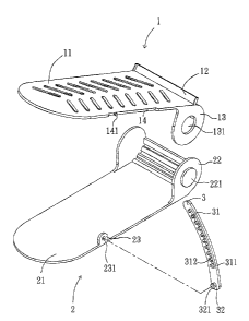
Fig. 1 is an exploded view to show the first embodiment of the shoes frame of
the present invention;
Fig. 2 is an exploded view to show the second embodiment of the shoes frame
of the present invention;
Fig. 3 is an exploded view to show the third embodiment of the shoes frame
of the present invention;
Fig. 4 is an exploded view to show the fourth embodiment of the shoes frame
of the present invention;
Fig. 5 is an exploded view to show the sixth embodiment of the shoes frame
of the present invention;
Fig. 6 is an exploded view to show the seventh embodiment of the shoes
frame of the present invention, and
7

CA 02824245 2013-07-09
Fig. 7 is an exploded view to show the eighth embodiment of the shoes frame
=
of the present invention.
DETAILED DESCRIPTION OF THE PREFERRED EMBODIMENT
Referring to Fig. 1, the adjustment shoes frame of the present invention
comprises a top part 1 having a first surface 11 and a first pivotal portion
13, and a stop
plate 12 extends perpendicularly from an underside of the first surface 11 so
that when a
shoe is put on the first surface 11, the stop plate 12 stops the shoe from
slipping off the
first surface 11 when the first part 1 is orientated at an angle. The first
pivotal portion
13 has a hole 131 defined therethrough which is pivotably connected with a
second part
2. The top part 1 includes a recess 14 defined in a side thereof and a stud
141 extends
from the recess 14 so as to be connected with an adjustment rod 3 to set the
position of
the first part 1.
The bottom part 2 has a second surface 21 for a shoe to be put thereon and a
second pivotal portion 22 extends perpendicularly from an underside of the
second
surface 21. The second pivotal portion 22 has a protrusion 221 which is
pivotably
engaged with the hole 131 of the first pivotal portion 13. The side of the
second surface
21 of the second part 2 is in alignment with the second pivotal portion 22,
and a lug 23
extends from the second surface 21. The lug 23 has an aperture 231 and the
adjustment
rod 3 is connected to the aperture 231.
An adjustment device includes the adjustment rod 3 which is a curved rod and
is connected between the top and bottom parts 1, 2. The adjustment rod 3
includes a
3

CA 02824245 2013-07-09
positioning portion 31 which includes a guide groove 311 and multiple notches
312.
The stud 141 on the first part 1 is movable in the guide groove 311 and
engaged with
one of the notches 312 to set the desired angular distance between the top and
bottom
parts 1, 2. A pivot 32 extends from the adjustment rod 3 and is pivotably
engaged with
the aperture 231 of the lug 23 of the second part 2. The pivot 32 includes an
enlarged
head 321 so that when the pivot 32 is engaged with the aperture 231, the pivot
32 is not
separated from the lug 23 of the second part 2.
The first and second surfaces 11, 21 are located on different planes so that
the
two shoes can be put on the first and second surfaces 11, 21 respectively.
This saves the
space in horizontal direction. The top part 1 is pivotable relative to the
second part 2,
and the adjustment rod 3 sets the angular distance between the top and bottom
parts 1, 2
so that the different types of shoes can be put on the top and bottom parts 1,
2. The stud
141 is slidable with in the guide groove 311 of the adjustment rod 3 and
engaged with
one of the notches 312 so that the user can easily adjust the relative
positions of the top
and bottom parts 1, 2.
The hole 131 of the top part 1 and the protrusion 221 of the bottom part 2 can

be switched to each other, which means that the first pivotal portion 13 of
the top part 1
is a protrusion and the second pivotal portion 22 of the bottom part 2 is a
hole. Similarly,
the pivot 32 of the adjustment rod 3 and the lug 23 of the bottom part 2 can
also be
switched to each other.
4

CA 02824245 2013-07-09
The second embodiment in Fig. 2 is made based on the first embodiment. The
main change is that multiple positioning holes 132 are located around the hole
131, and
multiple bosses 222 are located around the protrusion 221. The protrusion 221
is
pivotably engaged with the hole 131 and the bosses 222 are engaged with the
positioning holes 132. Again, the positioning holes 132 and the bosses 222 can
be
switched to each other.
The third embodiment in Fig. 3 is made based on the first and second
embodiments. The main change is that the second pivotal portion 22 having a
hole 223
and a circular flange 2231 extends from a periphery of the hole 223. The
circular flange
2231 has threads 2232 defined in an outer periphery thereto. An inner cap 224
has a
tubular portion with a passage 2241 defined therethrough and ridges 2242 are
formed
on an outer periphery of the tubular portion. The inner cap 224 is threadedly
connected
to the threads 2232 of the circular flange 2231. An outer cap 225 has a
recessed portion
2251 and multiple reception grooves 2252 are defined in an inner periphery
thereof.
The tubular portion of the inner cap 224 is engaged with the recessed portion
2251 and
the ridges 2242 are engaged with the reception grooves 2252. A spring 226 is
located
between the passage 2241 and the recessed portion 2251. The outer cap 225
maintains
the top part 1 when the first and second pivotal portions 13, 22 are engaged
with each
other. When adjusting, the user pushes the outer cap 225 on the bottom part 2
to pivot
the top part 1 to a desired position and the outer cap 225 is released to set
the relative
positions of the top and bottom parts 1, 2.
5

CA 02824245 2013-07-09
The fourth embodiment in Fig. 4 is made based on the first, second and third
embodiments. The main change is that the second pivotal portion 22 has a
recess 223
and multiple engaging grooves 2233 are defined in an inner periphery of the
recess 223.
The inner cap 224 has multiple engaging ribs 2243 defined in an outer
periphery thereof
and the engaging ribs 2243 are engaged with the engaging grooves 2233. The
outer cap
225 has a recessed portion 2251 and multiple reception grooves 2252 are
defined in an
inner periphery thereof.
The ridges 2242 of the inner cap 224 and the reception grooves 2252 of the
outer cap 225 as shown in Figs. 3 and 4 can be switched to each other. This
means that
the inner cap 224 can have reception grooves and the outer cap 225 has
engaging ribs
which are engaged with the reception grooves. The inner periphery of the
recess 223 of
the bottom part 2 in Fig. 4 and the outer periphery of the inner cap 224 can
switch to
each other so as to be engaged with each other.
The sixth to eighth embodiments are shown in Figs. 5 to 7, wherein the main
change is that the stud 141 and the adjustment rod 3 are removed, and the top
part is
strong enough to support the weight of the shoe, then the stud 141 and the
adjustment
rod 3 are not necessary.
While we have shown and described the embodiment in accordance with the
present invention, it should be clear to those skilled in the art that further
embodiments
may be made without departing from the scope of the present invention.
6

Representative Drawing
A single figure which represents the drawing illustrating the invention.
Administrative Status

For a clearer understanding of the status of the application/patent presented on this page, the site Disclaimer , as well as the definitions for Patent , Administrative Status , Maintenance Fee  and Payment History  should be consulted.

Administrative Status

Title Date
Forecasted Issue Date Unavailable
(86) PCT Filing Date 2012-01-12
(87) PCT Publication Date 2012-07-19
(85) National Entry 2013-07-09
Dead Application 2017-01-12

Abandonment History

Abandonment Date Reason Reinstatement Date
2016-01-12 FAILURE TO PAY APPLICATION MAINTENANCE FEE

Payment History

Fee Type Anniversary Year Due Date Amount Paid Paid Date
Application Fee $400.00 2013-07-09
Maintenance Fee - Application - New Act 2 2014-01-13 $100.00 2014-01-09
Maintenance Fee - Application - New Act 3 2015-01-12 $100.00 2015-01-08
Owners on Record

Note: Records showing the ownership history in alphabetical order.

Current Owners on Record
CHEN, MING-TE
Past Owners on Record
None
Past Owners that do not appear in the "Owners on Record" listing will appear in other documentation within the application.
Documents

To view selected files, please enter reCAPTCHA code :


To view images, click a link in the Document Description column. To download the documents, select one or more checkboxes in the first column and then click the "Download Selected in PDF format (Zip Archive)" or the "Download Selected as Single PDF" button.

List of published and non-published patent-specific documents on the CPD .

If you have any difficulty accessing content, you can call the Client Service Centre at 1-866-997-1936 or send them an e-mail at CIPO Client Service Centre.


Document
Description 
Date
(yyyy-mm-dd) 
Number of pages   Size of Image (KB) 
Abstract 2013-07-09 1 13
Claims 2013-07-09 4 135
Drawings 2013-07-09 7 160
Description 2013-07-09 6 231
Representative Drawing 2013-07-09 1 29
Representative Drawing 2013-08-29 1 10
Cover Page 2013-09-30 1 38
PCT 2013-07-09 17 592
Assignment 2013-07-09 5 127
Correspondence 2013-09-12 1 52