Note: Descriptions are shown in the official language in which they were submitted.
CA 02824254 2013-07-09
WO 2012/126977 PCT/EP2012/055062
1
SPINDLE FOR WINDING UP CORELESS ROLLS OF A PLASTIC FILM
BACKGROUND OF THE INVENTION
The present invention relates to a spindle for winding up coreless rolls of a
plastic film, in particular rolls of a stretchable plastic film suitable for
packaging and/or for wrapping palletized loads or other applications.
STATE OF THE ART
Stretchable plastic films, wound up in rolls, are typically used in the
packaging field, for example, to wrap and stabilize loads and/or goods
stacked on support pallets.
Generally, the plastic film is wound up on a small rigid tubular core in
paperboard or plastic material, which has to be threaded in advance on a
spindle of a winding machine to wound a plastic roll or manually used by a
handle to unwound the roll. The use of small rigid cores in paperboard or
plastic material is necessary in order to allow a proper winding of the
plastic
film rolls, as well as to facilitate the withdrawal thereof at the end of the
winding step. However, the use of conventional small rigid tubular cores
necessarily involves some drawbacks in the provision and storage of new
tubular cores, as well as the disposal of the exhausted cores, with
associated increased costs.
The replacement of the conventional rolls of plastic film wound up on small
rigid cores, with coreless rolls, has long been sought, by directly forming
the
rolls on a spindle that, after the removal from the winding machine, could be
withdrawn from the roll only after a preset period of time needed to allow the
roll to stabilize, in order to avoid any implosion risk.
In an attempt to improve this technology, it has also been proposed, both in
CA 02824254 2013-07-09
WO 2012/126977 PCT/EP2012/055062
2
the packaging plastic film field, and in other fields, the use of drilled
spindles
having a perforate peripheral wall comprising a tubular chamber connectable
to a pressurised air source, and the supply of pressurised air through the
same spindle and the perforated wall in order to cause a slight expansion of
the internal turns of the roll, and an air flow which facilitates the
withdrawal
of the roll without having to remove the spindle from the winding machine.
The use of a perforated spindle for winding up coreless rolls of a stretchable
plastic film is shown, for example, in WO-A-2006/012933 of the same
Applicant; other examples for winding up web material, for example, paper or
fabric, are described in US-A-5,337,968; US-A-6,186,436; and US-A-
6,595,458.
In particular, WO-A-2006/012933 discloses a spindle comprising a tubular
body provided with a peripheral wall that defines an internal chamber axially
extending along the spindle, which is connectable to a pressurised air
source; the peripheral wall is provided with a plurality of perforations
extending from the internal chamber to the external surface of the spindle,
for winding up the plastic film and forming the roll.
In practice, the spindle is composed of a metal tubular body, the external
surface of which for winding up the film has to be suitably ground and made
perfectly smooth, so as to minimize the frictional forces which would prevent
the sliding and withdrawal of the roll; furthermore, the pressurised air that
is
ejected through the spindle perforations causes a radial expansion and a
compaction of the inner turns of the roll, thus allowing to easily withdrawing
the roll from the spindle, in the absence of frictional forces and without
causing any deformation of the same roll, or implosion of the inner turns
thereof.
However, during the use of such a spindle, a high compressed air
consumption has been noted, that is necessary, on the other hand, to cause
CA 02824254 2013-07-09
WO 2012/126977 PCT/EP2012/055062
3
the radial expansion of the inner turns of the roll upon the withdrawal.
Besides a reduction of the compressed air consumption, there is also the
need to adhere automatically the plastic film to the external surface of the
spindle, at the beginning of the film winding step. This second need, which
partially contrasts with the need to reduce the frictional forces upon the
withdrawal of the roll, is incompatible with the previous one, and not easy to
solve.
In an attempt to partially obviate this drawback, US-A-5,337,968 suggests to
connect the perforated spindle to a vacuum pump, at the beginning of the
winding step of the web material, so as to create a vacuum degree by
suctioning air through the spindle perforations, in order to initially adhere
the
web material against the external surface of the spindle.
Such a solution, beside being constructively and functionally complex, is not
applicable to plastic film winding machines in which use is made of
compress air to cause the radial expansion of the inner turns of the roll upon
the withdrawal, since, in order to generate the powerful air jets necessary to
expand the turns of the roll, perforations are needed having a small
diameter, of the order of a millimetre, slightly greater or smaller; on the
contrary, to draw the film and make it to pneumatically adhere to the spindle
at the beginning of the winding step, perforations would be needed having a
considerably greater diameter, so as to generate a vacuum degree or
underpressure condition necessary to draw the film. These two operative
conditions are mutually incompatible, and it does not seem that they can co-
exist in a single spindle.
Finally, in the conventional spindles, in which the exit holes for air jet
open
on a smooth surface, that is deemed necessary to reduce the frictional
forces upon withdrawal of the rolls, withdrawal difficulties have sometimes
occurred due to an unhomogeneous distribution of the pressurised air
CA 02824254 2013-07-09
WO 2012/126977 PCT/EP2012/055062
4
cushioning between opposed surfaces of the spindle and the roll,
presumably due to an irregular radial expansion of the roll.
OBJECTS OF THE INVENTION
Therefore, the need exists to find a new and different solution, which allows
obviating the drawbacks indicated before, by reducing the consumption of
pressurised air necessary to cause the radial expansion of the internal turns
of the roll during the removal.
Therefore an object of the invention is to provide a spindle suitable for
winding up coreless rolls of plastic films, in particular, stretchable films,
which is provided with a plurality of perforations for the generation of air
jets
and a film winding surface suitably configured to provide a low frictional
force, as well as to allow the creation of an uniform air cushioning along the
entire spindle, during the withdrawal step of a roll.
A further object of the invention is to provide a spindle as defined before,
that is also provided with a film winding surface, which is suitably treated
to
allow an automatic adhesion of the plastic film at the beginning of the
winding of a roll, as well as provided with a high hardness and wear and/or
etching resistant surface, while maintaining such features for a prolonged
working period of time.
BRIEF DESCRIPTION OF THE INVENTION
What stated above can be achieved by a spindle suitable for winding up
coreless rolls of a plastic film, in particular a stretchable film, according
to
claim 1.
According to the invention, a spindle suitable for winding up and removing
coreless rolls of a plastic film, as defined before, has been provided,
wherein
CA 02824254 2013-07-09
WO 2012/126977 PCT/EP2012/055062
the spindle comprises:
a tubular body having a peripheral wall and at least a coaxially
extending internal chamber, connectable to a pressurised air source; and
in which the peripheral wall of the spindle comprises a plurality of
5 perforations extending from the internal chamber to an external surface
for
winding up a roll,
characterized in that
the peripheral wall of the spindle has a protective surface layer of hard
chrome defining the external surface for winding up the roll, having an
average roughness between 6 and 6.5 pm, obtained by sandblasting.
Sandblasting is a mechanical process by which it is aimed to erode the
surface portion of a material, by means of sand and air jets oriented against
the surface to be treated.
Sandblasting is frequently used for the surface cleaning of metals or
materials in general, or to etch writings and/or images on marble and stones,
as well as to confer to the treated surface a final aesthetical appearance.
At the end of a sandblasting operation, the treated surface has a degree of
roughness that depends on both the dimensions of the grains of sand that
are used, and the pressure of the jet.
Generally, the dimensions of the sand grains can by average range from
about 0.250 mm to 1 mm, typically using grains of sand having greater
dimensions when operating on hard materials.
A typical sandblasting operation, conversely to the needs of the present
invention, tends to roughen the treated surface and to increase the frictional
forces; furthermore, from the first tests that have been carried out, it has
been ascertained that an incorrect sandblasting, besides negatively
increasing the frictional forces, tends to create an excessive consumption of
CA 02824254 2013-07-09
WO 2012/126977 PCT/EP2012/055062
6
compressed air. Therefore, sandblasting would seem completely unsuitable
for a surface treatment of spindles for winding up and removal of coreless
rolls, in which use is made of pressurised air jets in order to withdraw the
roll
at the end of the winding step.
Against all expectations, instead, it has been ascertained that by carrying
out a sandblasting under preset conditions, both an initial automatic
adhesion of the plastic film to the sandblasted surface of the spindle, and
the
creation of an homogeneous air cushioning between the roll and the spindle,
with consequent low frictional force between the opposite surfaces of the roll
and the spindle and a reduced consumption of pressurised air is made
possible.
BRIEF DESCRIPTION OF THE DRAWINGS
These and further characteristics of the spindle according to the present
invention will be more apparent from the following description and the
annexed drawing, in which:
Fig. 1 is a longitudinal cross-sectional view of the spindle;
Fig. 2 is an enlarged, cross-sectional view, taken along the line 2-2 of
Fig. 1;
Fig. 3 is an enlarged detail of Fig. 2;
Fig. 4 shows a highly enlarged view of the sandblasted surface of the
spindle of Fig. 1.
DETAILED DESCRIPTION OF THE INVENTION
Figs. 1 and 2 show a general spindle 10 suitable for winding up one or more
rolls 11 of a plastic film, for example, a stretchable film. The spindle 10
comprises a tubular body 12 in steel material, obtained for example by
drawing, suitably ground with a slight taper, for example, of 2 or 3 degrees,
with a minimum diameter at the fore end for the removal of the roll 11.
CA 02824254 2013-07-09
WO 2012/126977 PCT/EP2012/055062
7
The tubular body 12 is fastened, for example welded at an end of a shaft 13,
by which the spindle 10 is supported in order to freely rotate; the tubular
body 12 of the spindle 10 has a peripheral wall defining an internal chamber
14 coaxially extending to the tubular body 12. The chamber 14 of the
spindle, at the fore end for the removal of the roll 11, is closed by a plug
15,
while the rear end can be made to communicate with a pressurised air
source through an air supply channel 16 longitudinally extending to the shaft
13.
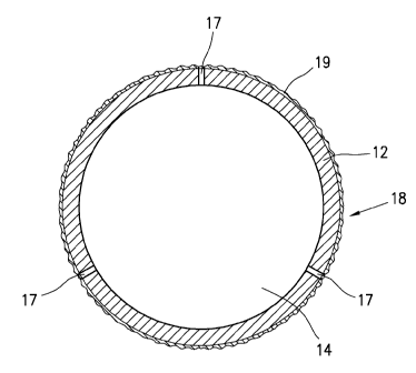
With reference again to Figs. 1 and 2, the peripheral wall of the tubular body
12 has a plurality of perforations 17 extending from the internal chamber 14
to an external surface 18 for winding up the plastic film.
The spindle 10 can be of any external diameter, for example, ranging
between 35 and 100 mm, while the diameter of the holes or perforations 17
can be about 1 mm, slightly greater or lower. The same number of the holes,
and the arrangement thereof, both angularly and along the longitudinal axis
of the spindle, can be any one, depending on the length and the outer
diameter of the spindle. In the example shown, the holes 17 are arranged at
a constant pitch, by alternately providing for holes 17 that are angularly
spaced apart by an angle ranging between 90 and 180 ; however, any other
arrangement of the holes 17 is possible, with respect to the one that has
been shown.
According to the present invention, as shown in Fig. 2 and the enlarged
detail of Fig. 3, the tubular wall of the body 12 of the spindle has been
coated with a thin protective layer 19 of hard chrome, obtained by a so-
called "FLASH" deposition process, consisting in a deposition of chrome
having an average thickness ranging between 8-15 pm, and a hardness
ranging, for example, between 1000 and 1200 HV.
CA 02824254 2013-07-09
WO 2012/126977 PCT/EP2012/055062
8
The choice of the hard chrome FLASH technology, after several attempts,
has been made for both the possibility to distribute in a precise and uniform
manner the chrome layer 19 without the need for successive grinding
operations, and the lower difficulty in obtaining the required surface
roughness by dry sandblasting, as explained herein below.
In fact, according to the most innovative aspect of the present invention, for
the objects defined before, the external surface of the layer 19 of hard
chrome, defining the surface 18 for winding up the roll 11, is subject to a
dry
sandblasting process in order to form a rough surface having an average
roughness Ra ranging between 6 and 6.5 pm.
To the aims of the present invention, based on a conventional definition, by
average roughness Ra is meant the arithmetic average of the absolute
values of all the ridges 19A and all the valleys 19B of the layer 19 of hard
chrome, measured along a sample length.
A number of tests have been carried out with sand having different particle
sizes; however, good results have been obtained by using grains of sand
having a same dimension ranging between 0.15 and 0.3 mm.
After several attempts, it has been concluded that the use of grains of sand
having a greater size would give rise to the risk of creating an excessively
high roughness, with consequent increase of the air amount to be supplied
to the spindle; furthermore, it would give rise to the risk of damaging the
thin
chrome layer during the sandblasting process. Finally, excessively high
frictional forces would be created in those areas in which the air cushioning
would lack due to the excessive extent of roughness, which would hinder the
withdrawal of the roll 11.
Instead, from the tests that have been carried out, it has been ascertained
that by carrying out a dry sandblasting such as to create an average
CA 02824254 2013-07-09
WO 2012/126977 PCT/EP2012/055062
9
roughness Ra having the values cited before, it is possible to meet two
conflicting need in a single spindle: the first need being to provide the
spindle with a rough surface suitable to allow an automatic initial adhesion
of
the plastic film, without having to generate any air suction through the
perforation; the second need being to provide the spindle with a degree of
roughness suitable to generate an homogeneous pressurised air cushioning
upon withdrawal of the roll, with a considerably reduced pressurised air
consumption.
Since it is extremely difficult to represent the irregular profile of a
sandblasted surface, the detail of Fig. 3 has to be meant as merely indicative
of the general features of the layer 19 of chrome, after the sandblasting
process.
In turn, Fig. 4 shows, again as a way of example, the roughness
characteristics of the sandblasted surface 18 of the layer 19 of chrome of the
spindle according to the invention; from Figs. 3 and 4 it is noted that the
random sequence of ridges 19A and valleys 19B generates an infinity of
surface micro-paths, with consequent homogeneous distribution of the air
flows, thus minimizing the contact points, and, as a result, the frictional
forces against the plastic film during the withdrawal of the roll 11.
From what has been stated and shown in the example of the annexed
drawings, it will be apparent that a spindle suitable for winding up coreless
rolls of a plastic film in winding machines is provided, in which the spindle
comprises a tubular body connectable to a pressurised air source, the
peripheral wall of which is provided with a plurality of perforations for the
generation of air jets, and in which the peripheral wall of the spindle has a
thin coating of hard chrome, which has been suitably roughened by a
suitable dry sandblasting process in order to create a preset roughness
degree.
CA 02824254 2013-07-09
WO 2012/126977 PCT/EP2012/055062
However, it is meant that what has been stated and shown with reference to
the annexed drawings, has been given only by way of illustration of the
general and innovative characteristics of the spindle according to the
present invention. Therefore, other modifications or variations will be able
to
5 be made to the spindle, or parts thereof, without for this departing from
the
claims.