Note: Descriptions are shown in the official language in which they were submitted.
FOAM WALL STRUCTURE
BACKGROUND OF THE INVENTION
Field of the Invention
[0002] The present invention relates generally to wall systems, and, in
particular, to a foam
wall structure.
Description of Related Art
[0003] Insulated wall panels provide thermal insulation for residential
homes and buildings.
A wall panel's R-value is its ability to impede heat flow. The greater the
ability to impede heat
flow, the higher the R-value. Over the years, insulation standards have become
more strict,
requiring higher R-values and continuous insulation on the exterior side of
insulated wall panels.
The current market solutions to these stricter requirements are (1) pre-
fabricated wall panels that
incorporate insulation at the construction site, and (2) Structural Insulated
Panels (SIPs).
[0004] The pre-fabricated wall panel that incorporates insulation at the
construction site is
the more widely adopted solution in the market. However, pre-fabricated wall
panels that
incorporate high-quality insulation at the construction site require a
separate sub-contractor for
on-site insulation with fiberglass batting, which is known to have suboptimal
R-values.
Fiberglass is not an air barrier and allows for air intrusion, thus,
increasing the probability of
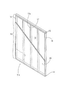
condensation and mold growth within wall systems. Furthermore, additional
material is
necessary to finish the wall (e.g., Oriented Strand Boards (OSBs) and house
wrap), and the
overall construction process duration is extended, thereby, increasing
possible risk of trade
scheduling conflicts. Installing insulation onsite also leads to potential
inconsistencies in
insulation installation, performance, risk, and usage.
[0005] The second solution, SIPs, also have several drawbacks. SIPs
typically utilize
expanded polystyrene (EPS) foam insulation sandwiched between two OSB boards,
which only
provide thermal performance of about R-4 per inch. Additionally, current SIPs
are mainly used
by smaller scale home builders with high levels of home customization.
[0006] A need, therefore, exists for an insulated wall structure that
satisfies the strict industry
insulation requirements and that can be made without excessive material and
labor costs.
1
CA 2824295 2019-12-10
SUMMARY OF THE INVENTION
[0007] According to one embodiment of the present invention, a foam wall
structure includes
a frame, at least one primary support member, and a foam layer. The frame can
include: a first
member; a second member spaced apart from the first member; and two side
members extending
between the first and second members. The first member, second member, and two
side
members each have a front surface and a rear surface that form the front frame
surface and the
rear frame surface of the frame. The at least one primary support member can
be positioned
between the two side members and extend between the first and second member.
The primary
support member defines a front primary support surface and an opposite rear
primary support
surface corresponding to the front frame surface and rear frame surface. The
foam layer can be
received within at least a portion of the frame and overlies the front surface
of the primary
support member to form an uninterrupted exposed foam surface.
[0008] According to another embodiment of the present invention, a method
of
manufacturing a foam wall structure includes: a) providing a frame with at
least one primary
support member; b) providing a rigid surface having a width equal to or
greater than the width of
the front frame surface and length equal to or greater than the length of the
front frame surface;
c) orientating the front frame surface over the rigid surface such that the
front frame surface is
substantially parallel to the rigid surface; d) depositing foam material into
the frame; and e)
allowing the foam material to expand within at least a portion of the frame,
wherein the foam
layer overlies the front support surface of the primary support member to form
an uninterrupted
exposed foam surface.
2
CA 2824295 2019-12-10
[0008a] According to another embodiment, there is provided a foam wall
structure
comprising: a) a frame comprising: a first member; a second member spaced
apart from the first
member; and two side members extending between the first and second members,
wherein the
first member, second member, and two side members each have a front surface
and a rear surface
that form the front frame surface and the rear frame surface of the frame; b)
at least one primary
support member positioned between the two side members and extending between
the first and
second member, wherein the primary support member defines a front primary
support surface
and an opposite rear primary support surface corresponding to the front frame
surface and rear
frame surface; and c) a foam layer bounded by the first, second, and two side
members of the
frame, wherein the foam layer overlies the front support surface of the
primary support member
to form a uniform and continuous exposed foam surface, wherein the foam layer
does not overlie
the front frame surface such that the foam layer is flush with the front frame
surface while
overlying the front support surface of the primary support member, and wherein
the foam layer is
dimensioned to extend from the uniform and continuous exposed foam surface to
a position
intermediate the front frame surface and rear frame surface such that a gap is
formed within the
frame between the foam layer and the rear frame surface, the gap extends the
distance between
the two side members.
[0008b] According to another embodiment, there is provided a method of
manufacturing a
foam wall structure comprising: a) providing a frame with at least one primary
support member
comprising: i) a first member; ii) a second member spaced apart from the first
member; iii) two
side members extending between the first and second members, the frame
defining a front frame
surface and an opposite rear frame surface, wherein the first member, second
member, and two
side members each have a front surface and a rear surface that form the front
frame surface and
the rear frame surface of the frame; and iv) at least one primary support
member positioned
between the two side members and extending between the first and second
member, wherein the
primary support member defines a front primary support surface and an opposite
rear primary
support surface corresponding to the front frame surface and rear frame
surface; b) providing a
rigid surface having a width equal to or greater than the width of the front
frame surface and
length equal to or greater than the length of the front frame surface; c)
orientating the front frame
surface over the rigid surface such that the front frame surface is
substantially parallel to the rigid
surface; d) depositing foam material into the frame; and e) allowing the foam
material to expand
2a
CA 2824295 2019-12-10
within at least a portion of the frame, wherein the foam material forms a foam
layer that overlies
the front support surface of the primary support member to form a uniform and
continuous
exposed foam surface, wherein the foam layer extends from the uniform and
continuous exposed
foam surface to a position intermediate the front frame surface and rear frame
surface such that a
gap is formed within the frame between the foam layer and the rear frame
surface.
[0008c] According to another embodiment, there is provided a foam wall
structure
comprising: a) a frame comprising: a first member; a second member spaced
apart from the first
member; and two side members extending between the first and second members,
wherein the
first member, second member, and two side members each have a front surface
and a rear surface
that form the front frame surface and the rear frame surface of the frame; b)
at least one primary
support member positioned between the two side members and extending between
the first and
second member, wherein the primary support member defines a front primary
support surface
and an opposite rear primary support surface corresponding to the front frame
surface and rear
frame surface; and c) a foam layer bounded by the first, second, and two side
members of the
frame, wherein the foam layer overlies the front support surface of the
primary support member
to form a uniform and continuous exposed foam surface, wherein the foam layer
does not overlie
the front frame surface such that the foam layer is flush with the front frame
surface while
overlying the front support surface of the primary support member, and wherein
the foam wall
structure is free of a rigid sheathing layer.
[0009] The present invention is also directed to a foam wall structure made
according to the
methods described herein.
BRIEF DESCRIPTION OF THE DRAWINGS
[0010] FIG. 1 is a front perspective view of a frame according to one
embodiment of the
present invention;
2b
CA 2824295 2019-12-10
CA 02824295 2013-08-21
[00111 FIG. 2 is a rear perspective view of the frame of FIG. 1 according to
one
embodiment of the present invention;
100121 FIG. 3 is a front perspective view of a foam wall structure according
to one
embodiment of the present invention;
[0013] FIG. 4 is rear perspective view of the foam wall structure of FIG. 3
according
to one embodiment of the present invention;
10014] FIG. 5 is a front view of a frame with a window according to one
embodiment
of the present invention;
[0015] FIG. 6 is a front view of a frame with a door according to one
embodiment of
the present invention;
[0016] FIG. 7 is a top cross-sectional view of the foam wall structure of FIG.
4
according to one embodiment of the present invention;
[0017] :FIG. 8A is a side cross-sectional view of the foam wall structure of
FIG. 4
according to one embodiment of the present invention;
[0018] FIG. 813 is a side cross-sectional view of the foam wall structure of
FIG. 4
according to one embodiment of the present invention;
[0019] FIG. 9 is a front perspective view of a foam wall structure according
to one
embodiment of the present invention;
100201 FIG. 10 is a rear perspective view of the foam wall structure of FIG. 9
according to one embodiment of the present invention;
[0021] FIG. 11 is a top cross-sectional view of the foam wall structure of
FIG. 9
according to one embodiment of the present invention;
[0022] FIG. 12A is a side cross-sectional view of the foam wall structure of
FIG. 9
according to one embodiment of the present invention;
[0023] FIG. 12B is a side cross-sectional view of the foam wall structure of
FIG. 9
according to one embodiment of the present invention;
[0024] FIG. 13 is a top cross-sectional view of a foam wall structure
according to one
embodiment of the present invention;
[0025] FIG. 14 is a top cross-sectional view of foam material being deposited
into a
frame according to one embodiment of the present invention;
[0026] FIG. 15 is a top cross-sectional view of foam material being deposited
into a
frame according to one embodiment of the present invention;
3
CA 02824295 2013-08-21
[00271 FIG. 16 is a top cross-sectional view of foam material being deposited
into a
frame according to one embodiment of the present invention; and
[00281 FIG- 17 is a top cross-sectional view of foam material being; deposited
into a
frame according to one embodiment of the present invention.
DESCRIPTION OF THE PREFERRED EMBODIMENTS
[00291 For purposes of the description hereinafter, spatial orientation terms,
if used,
shall relate to the referenced embodiment as it is oriented in the
accompanying drawing
figures or otherwise described in the following description. However, it is to
be
understood that the embodiments described hereinafter may assume many
alternative
variations and embodiments. It is also to be understood that the specific
devices
illustrated in the accompanying figures and described herein are simply
exemplary and
should not be considered as limiting.
[0030] As indicated, in certain embodiments, the present invention is directed
to a
foam wall structure 10 that includes a frame 11, at least one primary support
member 17,
and a foam layer 30 with an uninterrupted exposed foam surface 31. . In
certain
embodiments, as shown in FIGS. 1-2, the frame 11 may be defined by a first
member
12, a second member 14 spaced apart from the first member 12, and two side
members
16 extending between the first member 12 and the second member 14. l-n
certain.
embodiments, the first member 12, second member 14, and two side members 16
each
have a front surface 12, 14a, 16a and a rear surface 12b, 14b, 16b that define
a front
frame surface ha and a rear frame surface 11b, respectively.
[0031] The frame 11 can be constructed into different shapes depending on its
intended use. In certain embodiments, as shown in FIGS. 1-2, the frame 11 can
be
constructed as a conventional industry standard rectangular or square frame
11_ For
example, as shown in FIGS. 1-2, the first member 12 and second member 14 may
be
spaced apart and extend parallel to each other, and the two side members 16
may extend
perpendicular to the first member 12 and second member 14 so as to form a
rectangular
or square frame 11. The shape and design of the flame 11 is not so limited and
can be
constructed into any desired shape. Generally, the shape and design of the
frame 11 is
constructed in accordance with the floor plans designed for a particular home
or
4
CA 02824295 2013-08-21
100321 Referring to FIGS. 3-4, in certain embodiments, at least one primary
support
member 17 may be positioned between the two side members 16. The primary
support
members 17 may extend between the first member 12 and the second member 14.
The
primary support members 17 may define a front primary support surface 17a and
a rear
primary support surface 17b. As shown in FIGS_ 3-4, in certain embodiments,
the front
primary support surface 17a and rear primary support surface 17b correspond to
the front
frame surface lla and rear frame surface lib of the frame 11.
[00331 Referring again to FIGS. 3-4, in certain embodiments, the primary
support
members 17 may be spaced apart to form cavities 18. The cavities 18 may be
defined by
the area between the primary support members 17, side members 16, first member
12,
and/or second member 14. The size of each cavity 18 will vary based on the
size of the
frame 11, the distance between consecutively positioned primary support
rnenibers 17,
and the number of primary support members 17 present.
100341 Further, the primary support members 17, side members 16, first member
12,
and/or second member 14 may comprise one or more plates, boards, beams, or the
like.
For example, as shown in FIGS. 1-4, the first member 12 may include two
plates.
[00351 In certain embodiments, the two side members 16 and/or primary support
members 17 are fixedly engaged to the first member 12 and second member 14.
For
instance, in certain embodiments, the two side members 16 and/or primary
support
members 17 are fixedly engaged to the first member 12 and second member 14
with
fasteners. Suitable fasteners that can be used with the present invention
include, but are
not limited to, nails, staples, bolts, screws, and rivets. The first member
12, second
member 14, two side members 16, and primary support members 17 can be made of
various materials. For example, the first member 12, second member 14, two
side
members 16, and primary support members 17 can be made of wood, metal,
fiberglass,
plastic, or a combination thereof. The first member 12, second member 1.4, two
side
members 16, and primary support members 17 can be made of the same material or
different materials.
100361 Further, the dimensions of the first member 12, second member 14, two
side
members 16, and primary support members 17 will vary depending on the intended
use
of the frame 11. The first member 12, second member 14õ two side members 16,
and
primary support members 17 can each have any dimension. In certain
embodiments, the
first member 12, second member 14, two side members 16, and primary supper,
CA 02824295 2013-08-21
members 17 have the same dimensions. For example, the first member 12, second
member 14, two side members 16, and primary support members 17 may have the
same
width and height dimensions. In one non-limiting embodiment, the first member
12,
second member 14, two side members 16, and primary support members 17 all have
a
width and height dimension of nominally 2x4 inches. In another non-limiting
embodiment, the first member 12, second member 14, two side members 16, and
primary
support members 17 all have a width and height dimension of nominally 2x6
inches.
[00371 In certain embodiments, the first member 12, second member 14, and two
side
members 16 have the same dimensions that are different from the dimensions of
the
primary support members 17. For example, the first member 12, second member
14, and
two side members 16 may have the same width and height dimensions, and the
primary
support members 17 may have width and height dimensions that arc different
from the
first member 1.2, second member 14, and two side members 16. In one non-
limiting
embodiment, the first member 12, second member 14, and two side members 16
have a
width and height dimension of nominally 2x6 inches, and the primary support
members
17 have a width and height dimension of nominally 2x4 inches.
100381 In addition to the above, and as shown in FIGS. 5-6, one or more
secondary
support members 20 and/or tertiary support members 22 may be used. The
secondary
support members 20 and tertiary support members 22 may comprise one or more
plates,
boards, beams, or the like. The secondary support members 20 and tertiary
support
members 22 can be incorporated into the frame 11 to provide structural support
to form
spaces for windows and doors, and the like. Further, the secondary support
members 20
and tertiary support members 22 can have dimensions that are the same or
different from
the primary support members 17, side members 16, first member 12, and/or
second
member 14. In one embodiment, the secondary support 1Tlembers 20 and tertiary
support
members 22 have greater lengths than the primary support members 17, side
members
16, first member 12, and/or second member 14.
[0039] As shown in FIGS. 5-6, the secondary support members 20 may have a
front
secondary support surface 20a and a rear secondary support surface (not shown)
that
correspond with the front and rear frame surfaces 11a, llb and the front and
rear primary
support surface 17a, 17b. Similarly, the tertiary support members 22 may have
a front
tertiary support surfaces 22.a and a rear tertiary support surface 22b (shown
in FIG. 17)
6
CA 02824295 2013-08-21
that correspond with the front and rear frame surfaces 11a, 11b and the front
and rear
primary support surfaces 17a, 17b.
[0040] in certain embodiments, the secondary support members 20 extend between
and attach to primary support members 17, or alternatively, the secondary
support
members 20 extend between and attach to a primary support member 17 and a side
member 16. In some embodiments, tertiary support members 22 extend between two
secondary support members 20 or between a secondary support member 22 and the
first
member 12 and/or second member 14.
100411 In certain embodiments, the secondary support members 20, tertiary
support
members 22, primary support members 17, side members 16, first member 12,
and/or
second member 14 forn a secondary cavity 26. As shown in FIGS. 5-6, the
secondary
cavity 26 can be used as a space for a window, door, or any other opening. For
example,
in certain embodiments, the secondary support members 20, tertiary support
members
22, primary support members 17, side members 16, first member 12, and second
member
14 can be constructed as a conventional industry standard rectangular or
square wall
panel having a window, door, or any other opening. For example, referrinR to
FIG. 5, a
rectangular or square wall panel having a window can be formed as follows: a
first
member 12 and second member 14 may be spaced apart and extend parallel. to
each
other; two side members 16 may extend between the first member 12 and second
member 14 in a direction perpendicular to the fast member 12 and second member
14;
primary support members 17 may be positioned between the side members 16 and
extend between the first member 12 and second member 14 J.n a direction
perpendicular
to the first member 12 and second member 14; two secondary support members 20
may
be spaced apart and extend between primary support members 17 in a direction
parallel
to the first member 12 and second member 14; and two tertiary support members
22 may
be spaced apart and extend between the two secondary members 20 in a direction
perpendicular to the secondary support members 20 and the first member 12 and
second
member 14. In addition, primary support members 17 can also extend between the
secondary members 20 and the first member 12 and/or second member 14. As shown
in
FIG, 5, a secondary cavity 26 is formed between the secondary support members
20 and
tertiary- support members 22. The resulting rectangular or square wall panel
can be used
in a residential home or building. The shape and design is not so limited and
can assume
any shape and design as desired,
7
CA 02824295 2013-08-21
[0042] In certain embodiments, additional support members and structural
elements
may also be used depending on the intended use of the foam wall structure 10.
For
example, and as shown in FIGS. 5 and 6, a header 28 may be used to provide
additional
support for a door or window. Other additional support members may be used for
structural purposes, design purposes, and the like.
[0043] In certain embodiments, a foam material can be deposited into the frame
it
As used herein, the term "foam material" refers to a substance that is formed
by trapping
pockets of gas in a liquid or solid. In certain embodiments, the foam material
is a closed-
cell foam. As used herein, "closed-cell foam" refers to foam that contains
discrete, non-
interconnecting cells. Non-limiting examples of foam, material that can be
used with the
present invention include materials made with polyurethane, polyisocyanurate
(also
referred to as polyiso), and mixtures thereof
[0044] In some embodiments, -the foam material may be substantially free, may
be
essentially free, and may be completely free of halogen containing flame
retardant
additives_ The term "halogen" refers to the halogen elements, which include
fluorine,
chlorine, bromine and iodine, and the term "halogen containing flame retardant
additives" refers to a substance that may be used to inhibit or resist the
spread of fire and
which contains halogen groups such as a fluoro, chloro, bromo and/or iodo
group.
Further, the term "substantially free" as used in this context means the 'foam
material
contains less than 1000 parts per million (ppm), "essentially free" means less
than 100
pprn, and "completely free" means less than 20 parts per billion (ppb) of
halogen
containing flame retardant additives.
[0045] As shown in FIGS. 3-4 and 7-8, the foam material can be deposited into
the
frame 11 such that the foam material forms a foam layer 30 within at least a
portion of
the frame 11 between the front frame surface 11a and the rear frame surface 11
b. As
shown in FIG-. 7-8, the foam layer 30 may extend beyond the front primary
support
surfaces 17a such that the foam layer 30 overlies the front support surfaces
17a to form a
continuous or uninterrupted exposed foam surface 31. As used herein,
"continuous or
uninterrupted foam layer" refers to a foamed material that is connected or
bonded along
at least one path without a break or interruption.
[0046] In certain embodiments, referring to FIGS. 3 and 7-8, the foam layer 30
extends beyond the front primary support surfaces 17a and the front frame
surface 11a.
As such, the foam layer 30 forms a continuous or uninterrupted exposed foam
surface 31
8
CA 02824295 2013-08-21
over the front primary support surfaces 17a and the front frame surface llaõ
which can
be seen in the top cross-sectional view of FIG. 7 and the side cross-sectional
view of
FIGS. 8A and 8B. As shown in FIGS. 7-8õ the continuous or uninterrupted
exposed
foam surface 31 can extend over the entire front frame surface 11a.
[0047] Referring to FIGS. 9' and 1142, in certain embodiments, the foam layer
30
does not extend beyond the front frame surface 11a, and only extends beyond
the front
primary support surfaces 17a. Accordingly, in some embodiments, the foam layer
30
forms a continuous or uninterrupted exposed foam surface 31 over the front
primary
support surfaces 17a and is flush or contained between the front and rear
frame surfaces
11, 11b. As shown in FIGS. 11-12, the continuous or uninterrupted exposed foam
surface 31 can overlay all the front primary support surfaces 17a.
[0048] Referring to FIGS. 7 and 11, the foam layer 30 can be dimensioned to
expand
from the uninterrupted exposed surface 31 to a position intermediate the front
frame
surface ha and rear frame surface 11b, thereby forming a gap or opening 40
within the
foam wall structure 10 between the foam layer 30 and the rear frame surface
11b. FIGS.
4 and 10 further show that this gap 40 can be used as an area to incorporate
home 'utility
components 42 such as electrical wires, cords, heating and cooling pipes, and
plumbing
fixtures. These home utility components 42 may be inserted into the gap 40
located
between the foam layer 30 and the rear frame surface llb such that utility
components
42 are not surrounded or contacting the foam layer 30. In. certain
embodiments, the gap
40 comprises at least two inches as measured between the foam layer 30 and the
rear
frame surface 11b.
[0049] ID certain embodiments, when secondary support members 20 and/or
tertiary
support members 22 are used with the foam wall structure 10 to form a
secondary cavity
26, the secondary cavity 26 can be free of foam. For example, in some
embodiments, the
foam layer 30 does not extend beyond and over the front secondary support
surfaces 20a
of the secondary members 20, the front tertiary support surfaces 22a of the
tertiary
support Members 22, and/or beyond and over at least a portion of the front
surfaces of
other members that help form the secondary cavity 26. FIG. 13 shows a top
cross-
sectional view with the foam layer 30 not extending beyond the front tertiary
support
surfaces 22a according to one embodiment.
[0050] Further, the foam layer 30 can be formed in-situ during the
manufacturing
process. The term "formed in-situ during the manufacturing process" refers to
the
9
CA 02824295 2013-08-21
foo ___________________________________________________________ nation of a
foam layer 30 with an uninterrupted exposed foam surike.31 as described
herein during manufacturing of the foam wall structure 10 off-site at a
facility remote or
away from a building construction site. As such, the foam layer 30 with an
uninterrupted
exposed foam surface 31 may not be formed at a construction site as is
required by
conventional methods.
[00511 The foam layer 30 having a continuous or uninterrupted exposed foam
surface
31 is able to fill tight spaces and seal gaps that are not visible to the
naked eye. The
foam layer 30 with an uninterrupted exposed foam surface 31 also acts as a
vapor and
thermal insulating barrier, which reduces energy consumption in buildings and
residential homes when the present invention is used as a wall panel. In
addition, the
foam layer 30 with an uninterrupted exposed foam surface 31 provides
structural
stability to the foam wall structure 10 such as improved wall racking
strength. As used
herein, "wall racking strength- refers to the ability of a wall structure to
maintain its
shape under duress_
[00521 Referring to FIGS. 7 and 11, in certain embodiments, the continuous or
uninterrupted exposed foam surface 31 may include a coating 36 adhered to at
least a
portion of the exposed foam surface 31. As used herein, the term "coating"
includes a
partial or continuous film or layer that can be applied to a surface. Non-
limiting
examples of coatings 36 that can be adhered or attached to the exposed foam
surface 31
includes coatings 36 that provide protection from ultraviolet (LTV) radiation,
weathering,
or a combination thereof The coating 36 can also provide stability to the
exposed foam
surface 31. For example, the coating 36 may include fibrous materials such as,
but not
limited to, glass fibers.
[0053] Further, in certain embodiments, the foam wall structure 10 does not
include a
rigid sheathing layer. As used herein, the term "rigid sheathing layer" refers
to a layer
applied to at least a portion of the front frame surface 11.a or rear frame
surface 11b.
Non-limiting of sheathing layers include boards, plates, and the like. For
instance, the
foam wall structure does not include foam boards, woad boards, metal boards,
gypsum
boards, paper boards, polymeric foam boards, plates, and the like. Examples of
such
sheathing layers are disclosed in U.S. Patent No. 8,397,465 and U.S. Patent
Application
Publication No. 2012/0011792. The foam wall structure 10, excluding such
materials
according to the present invention, is able to flex or deform under a load and
return to its
CA 02824295 2013-08-21
original design while retaining its structural stability, racking strength,
and other physical
characteristics.
[0054] The present invention is also directed to methods of making a foam wall
structure 10. In certain embodiments, a method of making a foam wall structure
10
includes first constructing a frame 11 having at least one primary support
member 17.
The frame 11 having at least one primary support member 17 can be constructed
in
accordance with any of the embodiments disclosed herein. Referring to FIGS- 14-
17,
after constructing the frame 11 with at least one primary support member 17,
the front
frame surface 17a can be orientated over a rigid surface 50 such that the
front frame
surface 11a is positioned parallel or at least substantially parallel to the
rigid surface 50.
A "rigid surface" refers to any surface that is capable of receiving the frame
11 without
bending, flexing, or moving. In certain embodiments, and as shown in FIGS. 14-
17, the
rigid surface 50 has a width equal to or greater than the width of the front
frame surface
1.1a and a length equal to or greater than the length of the front frame
surface 11a. In
one non-limiting example, the rigid surface 50 is substantially horizontal.
[0055] After orientating the front frame surface 17a over the rigid surface
50, a foam
material can be deposited into the frame 11. The foam material may be
deposited with
an automated delivery device_ Alternatively, the foam may be deposited using
various
other devices including, but not limited to, a foam dispensing gun that is
controlled and
carried by an individual user_ In one embodiment, as shown in FIGS. 14-17, the
foam
material is deposited with an automated foam dispensing rig 60 that can be
calibrated to
dispense a pre-deteituined amount of foam. The foam dispensing rig 60. can
include one
or more nozzles 62. The nozzles 62 can be positioned over the frame 11 of the
foam
wall structure 10 so that each nozzle 62 sprays or pours foam into cavities 18
located
within the frame 11 such as the cavities 18 shown in FIG. 3. A foam dispensing
rig 60
with a plurality of nozzles 62 makes it possible to dispense foam quickly and
efficiently.
In certain embodiments, the nozzles 62 can move into different positions.
[00561 Referring to FIGS. 14-17, in certain embodiments, the foam material may
be
deposited so that the foam material contacts the rigid surface 50. As shown in
FIG. 14,
the material may be deposited so that a foam layer 30 extends beyond the front
primary
support surfaces 17a and the front frame surface 11a. As such, the foam layer
30 forms
a continuous or uninterrupted exposed foam surface 31 over the front primary
support
surfaces 17a and the front frame surface 11a.
11
,
CA 02824295 2013-08-21
[0057] Retelling to FIG. 16, in certain embodiments, the foam material is
deposited
so that the foam layer 30 does not extend beyond the front frame surface 11a.
Accordingly, in some embodiments, the foam material is deposited so that a
foam layer
30 forms a continuous or uninterrupted exposed foam surface 31 over the front
primary
support surfaces 17a and is flush or contained between the front frame surface
lla and
rear frame surface 11 b.
[00581 As shown in FIGS. 15-16, the foam material can be deposited so that the
foam
layer 30 can expand from the uninterrupted exposed surface 31 to a position
intermediate
the front frame surface 11a and rear frame surface 1lb. A gap or opening 40
can
therefore be formed between the foam layer 30 and the rear frame surface lib
to
incorporate home utility components 42 such as electrical wires, cords,
heating and
cooling pipes, and plumbing fixtures, as can be seen in FIGS. 4 and 10.
[0059] Referring to FIG. 14, the front frame surface 11a can be moved away
from or
elevated to a position above the rigid surface 50. The front frame surface 11a
can be
elevated above the rigid surface 50 using an elevation device including, but
not limited
to, an industrial panel raiser. in operation, the elevation device holds the
front frame
surface Ha securely in place at a specified distance above the rigid surface
50_ The
higher it is elevated above the surface, the farther the foam layer 30 will
extend beyond
and over the front primary support surfaces 17a and/or the front frame surface
lie.
Alternatively, in some embodiments, the front frame surface ha can be placed
onto the
rigid surface 50, as shown in FIG. 15.
[0060] As shown in FIGS. 14 and 16, a form 70 can be used to prevent foam
material
from extending out from the outside perimeter of the frame 11. As used herein,
a
"form" refers to a barrier that prevents foam or other materials from
expanding outside
the perimeter of the frame 11. The form 70 may be positioned around the
outside
perimeter of the frame 11. As shown in FIG. 16, a second form 72 may be
positioned
between adjacent primary support members 17 to prevent foam material 30 from
expanding into undesired areas.
[0061] Referring to FIG_ 14, in one non-limiting embodiment, the front &eine
surface
11a can be elevated above a rigid surface 50 and foam material can be
deposited such
that a foam layer 30 is formed with an uninterrupted exposed surface 31 over
the front
primary support surfaces 17a and the front frame surface Ha. The foam material
can be
deposited so that the than' layer 30 can expand from the uninterrupted exposed
surface
12
CA 02824295 2013-08-21
31 to a position intermediate the front frame surface 11a and rear frame
surface 11b. A
form 70 can be placed around the perimeter of the frame 11 to prevent foam
material
from expanding outside the perimeter of' the frame 11.
[00621 As shown in FIG. 15, in another non-limiting embodiment, the front
frame
surface ha can be placed onto the rigid surface 50. As shown in FIG. 13, foam
material
can be deposited such that a foam layer 30 is formed with an uninterrupted
exposed
surface 31 extending over the front primary support surfaces 17a and not the
front frame
surface 11a. As such, the foam layer 30 forms a continuous or uninterrupted
exposed
foam surface 31 over the front primary support surfaces 17a and is flush or
contained
between the front and rear frame surface 11a, 11b.
[00631 As indicated, the foam wall structure 10 can also include secondary
support
members 20 and tertiary support members 22 that form a secondary cavity 26
within the
frame 11. Accordingly, in certain embodiments, the methods described herein
include
constructing a frame 11 having one or more secondary support members 20 and
tertiary
support members 22. In certain embodiments, to prevent foam material from
entering
the secondary cavity 26, the dimensions of the secondary support members 20
and/or
tertiary support members 22 are [treater than the dimensions of the primary
support
members 17. FIG. 17 shows a top cross-sectional view of the process of
depositing
foam into a frame 11 with tertiary support members 22 having a greater height
than the
primary support members 17.
[0064] Referring to FIG. 14-17, in certain embodiments, a coating 36 is
deposited
onto at least a portion of the rigid surface 50. The coating 36 can be
deposited to provide
protection from ultraviolet (UV) radiation, weathering, friction,
contamination, or a
combination thereof. The coating 36 can also provide stability to the
uninterrupted
exposed foam surface 31. For example, the coating may include fibrous
materials such
as, but not limited to, glass fibers. The coating 36 can also be applied as a
release coat
that can include, for example, a wax material. The release coat allows the
uninterrupted
exposed foam surface 31 to separate from the rigid surface 50.
[00651 In certain embodiments, the coating 36 deposited onto at least a
portion of the
rigid surface 50 foams a film. To keep the film aligned along the rigid
surface 50, the
rigid surface 50 can include perforations, holes and the like where pressure
can be
lowered so as to pull the film against the rigid surface .50. In one
embodiment, the rigid
13
,
surface 50 is connected to a vacuum source V such as a vacuum table as shown
in FIG. 15.
[0066] After the foam layer 30 has expanded, the formed foam wall structure 10
can be removed
from the rigid surface 50 and shipped directly to a job site for use as a wall
panel. The foam wall
structure 10 can be installed without any additional steps, thereby reducing
the number of sub-
contractors necessary to complete the installation of a wall at a construction
site. In addition, the
foam wall structure 10 does not require additional materials such as rigid
sheathing, OSB boards,
and house wrap that are typically used in current residential building
practices. Therefore,
insulation costs would decrease. The present invention would also decrease the
overall cost per
square foot per R-value.
[0067] The foam wall structure 10 also imparts a higher wall racking strength
and improves
thermal performance in comparison to existing wall solutions through the
introduction of a foam
layer 30 with the uninterrupted foam surface 31. Further, the foam wall
structure 10 will help
meet future R-value industry standards that are expected to increase in
certain regions, while still
utilizing current wall designs. With current fiberglass insulation, builders
would have to convert
2x4-based wall designs to 2x6-based wall designs to ensure enough wall cavity
capacity for
additional insulation to meet such higher standards.
=
[0068] The methods described herein also improve the consistency of installing
insulation, and
make it easy to install electrical and plumbing components in the gap or
opening 40 of a wall
panel. The present invention would also decrease the overall cost per square
foot per R-value.
[0069] The foam wall structure 10 is not limited for use in newly constructed
homes and can be
used for residential exterior insulation retrofit applications. Accordingly,
another aspect of the
present invention is the replacement of wall panels in older homes and
buildings with the foam
wall structure 10 described herein.
[0070] While several embodiments of the invention were described in the
foregoing detailed
description, those skilled in the art may make modifications and alterations
to these embodiments
without departing from the scope of the invention. Accordingly, the foregoing
description is
intended to be illustrative rather than restrictive.
14
CA 2824295 2019-12-10