Note: Descriptions are shown in the official language in which they were submitted.
CONSTRAINED KNEE PROSTHESIS
TECHNICAL FIELD
This disclosure relates to knee prostheses.
BACKGROUND
Total knee replacement systems often include a tibial implant and a femoral
implant that replace the articular surfaces of the knee. Posterior-stabilized
knee
replacement systems can be used to replace the function of both the anterior
cruciate
ligament (ACL) and posterior cruciate ligament (PCL). In some instances,
posterior-
stabilized knee replacement systems include varus/valgus constraint to also
replace the
function of the medial collateral ligament (MCL) and the lateral collateral
ligament
(LCL). Although a constrained knee replacement system can provide needed
stability, it
often introduces biomechanical inefficiencies.
SUMMARY
In a general aspect, a tibial insert provides varus/valgus constraint and
permits
tibiofemoral rotation. The tibial insert includes a post having walls
configured to engage
a femoral component over a flexion/extension range from extension to about 90
to about
120 degrees flexion. The post has rounded edges that permit tibiofemoral
rotation when
the post is in contact with the femoral component.
In another general aspect, a tibial insert includes a base and a post
extending from
the base along a longitudinal axis. The post has a medial surface, a lateral
surface, and a
height along the longitudinal axis. The medial surface has a medial section,
and the
lateral surface has a lateral section oriented substantially parallel to the
medial section.
The medial section and the lateral section each have a width in a
substantially anterior-
posterior direction that is sufficient to enable varus/valgus constraint over
a
CA 2824568 2018-04-30
CA 02824568 2013-06-28
WO 2012/103469
PCMJS2012/022958
flexion/extension range from extension to about 90 to 120 degrees of flexion
when the
tibial insert is mated with a femoral component.
Implementations can include one or more of the following features. For
example,
the femoral component defines an opening for receiving the post between
substantially
parallel walls, the opening providing a clearance of approximately 0.005
inches to
approximately 0.030 inches between the post and the substantially parallel
inner walls
when the post is received in the opening. The medial section and the lateral
section each
extend such that, along at least half of the height of the post, the width of
the medial
section and width of the lateral section in the substantially anterior-
posterior direction at a
given axial position along the longitudinal axis is between approximately one
sixth and
approximately two thirds of a largest width of the post in the substantially
anterior-
posterior direction at that axial position. The post has a proximal surface
that is
substantially flat and a notch defined in a superior anterior portion of the
post. At least a
portion of the notch is defined completely through the post along a medial-
lateral
direction. The medial section and the lateral section are substantially flat
and are oriented
along the substantially anterior-posterior direction. For substantially the
entire height of
the post, at a given axial position, the width of the medial surface and the
width of the
lateral surface in the substantially anterior-posterior direction are between
approximately
one sixth and two thirds of the largest width of the post in the substantially
anterior-
posterior direction at that axial position. The average length of the medial
surface in an
axial direction is more than twice the average length of the medial surface in
the
substantially anterior-posterior direction, and the average length of the
lateral surface in
an axial direction is more than twice the average length of the lateral
surface in the
substantially anterior-posterior direction. The post is twisted along the axis
of the post
such that a superior portion of the post is rotationally offset from an
inferior portion of
the post. The post is rotationally offset from the base such that the medial
surface and the
lateral surface are oriented at an angle with respect to medial and lateral
sides of the base.
The post has an anterior surface and a posterior surface, and the anterior
surface and the
posterior surface each have a convex portion. The post has rounded edges
between the
anterior surface and the medial and lateral surfaces and between the posterior
surface and
2
CA 02824568 2013-06-28
WO 2012/103469 PCMJS2012/022958
the medial and lateral surfaces. The rounded edges have a radius of between
approximately 0.030 and 0.090 inches.
In another general aspect, a method of operation of a knee prosthesis includes
permitting flexion/extension of the knee prosthesis over a flexion/extension
range of
approximately 0 to 150 degrees, constraining varus/valgus alignment of the
knee
prosthesis over a constrained flexion/extension range from extension to about
90 to 120
degrees of flexion, and rotating a tibial insert of the knee prosthesis
relative to a femoral
component of the knee prosthesis about a substantially superior-inferior axis
of the tibial
insert over at least a portion of the constrained flexion/extension range.
In another general aspect, a method of trialing a tibial insert of a knee
prosthesis
includes coupling a first tibial insert to a prepared tibia or a tibial tray,
assessing the
suitability of the knee prosthesis, and removing the first tibial insert from
the prepared
tibia or the tibial tray. The method includes coupling a second tibial insert
to the
prepared tibia or the tibial tray. The second tibial insert is configured to
permit
flexion/extension of the knee prosthesis over a flexion/extension range of
approximately
0 to 150 degrees, constrain varus/valgus alignment of the knee prosthesis over
a
constrained flexion/extension range from extension to about 90 to 120 degrees
of flexion =
when the tibial insert mated with a femoral component, and rotate the tibial
insert of the
knee prosthesis relative to the femoral component about a substantially
superior-inferior
axis of the tibial insert over at least a portion of the constrained
flexion/extension range.
Implementations can include one or more of the following features. For
example,
the first tibial insert and the second tibial insert each have a post, and the
first tibial insert
and the second tibial insert have differing post dimensions.
In another general aspect, a prosthesis includes a femoral component that
defines
an opening between substantially parallel inner walls and a tibial insert
having a base and
a post extending from the base. The post has a medial surface and a lateral
surface, and is
configured to be received in the opening. The medial surface has a medial
section, and
the lateral surface has a lateral section oriented substantially parallel to
the medial
section. The medial section and the lateral section each have a width in a
substantially
anterior-posterior direction that is sufficient to constrain varus/valgus
alignment of the
3
CA 02824568 2013-06-28
WO 2012/103469
PCT/US2012/022958
prosthesis over a flexion/extension range from extension to about 90 to 120
degrees of
flexion when the tibial insert is mated with the femoral component such that
the post is
received in the opening and the medial section and the lateral section each
engage one of
the substantially parallel inner walls. Engagement of the tibial insert and
the femoral
component rotates the tibial insert relative to the femoral component over at
least a
portion of the constrained flexion/extension range.
Implementations can include one or more of the following features. For
example,
the post is dimensioned to provide a total clearance of approximately 0.005 to
approximately 0.030 inches between the post and the substantially parallel
inner walls
when the post is received in the opening. The post has a posterior surface and
an anterior
surface, and the post has rounded edges between the anterior surface and the
medial and
lateral surfaces and between the posterior surface and the medial and lateral
surfaces.
The base has a medial bearing surface having a concave portion and a lateral
bearing
surface having a concave portion. The concave portion of the medial bearing
surface is
positioned anteriorly offset from a center of the base and has a maximum depth
in a
superior-inferior direction that is more inferior than a maximum depth of the
concave
portion of the lateral bearing surface in the superior-inferior direction. The
post has a
posterior surface, and the femoral component has an asymmetrical posterior cam
configured to engage the posterior surface to drive rotation of the tibial
insert relative to
the femoral component. The posterior cam is configured to engage the posterior
surface
at angles of flexion that are greater than a first angle that is between
approximately 60
and approximately 90 degrees of flexion, and the posterior cam is configured
to not
engage the posterior surface at angles of flexion less than the first angle.
The details of one or more implementations are set forth in the accompanying
drawings and the description below. Other features, objects, and advantages of
the
disclosure will be apparent from the description, the drawings, and the
claims.
BRIEF DESCRIPTION OF THE DRAWINGS
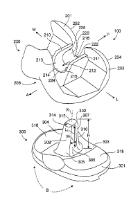
Fig. 1 is an exploded perspective view of a tibial insert and a femoral
component
of a left knee prosthesis.
4
CA 02824568 2013-06-28
WO 2012/103469
PCT/US2012/022958
Fig. 2 is an exploded posterior view of the tibial insert and the femoral
component.
Fig. 3 is a sagittal section view of the tibial insert and the femoral
component in
extension.
Fig. 4 is a top view of the tibial insert and the femoral component in
extension.
Fig. 5 is a top view of the tibial insert and the femoral component in
flexion.
Fig. 6 is a lateral view of the tibial insert showing a cross section of a
lateral
bearing surface.
Fig. 7 is medial view of the tibial insert showing a cross section of a medial
bearing surface.
Fig. 8 is a top view of the tibial insert showing a sectional view of a tibial
post
across line 8-8 of Figs. 6 and 7.
Fig. 9 is a top view of a tibial insert for a left knee with a laterally
rotated tibial
post.
DETAILED DESCRIPTION
Referring to Figs. 1 and 2, a knee prosthesis 100 provides varus/valgus
constraint
and also permits internal and external rotation of the tibia relative to the
femur. To
achieve this, the knee prosthesis 100 includes a tibial insert 300 shaped to
engage a
femoral component 200 to (i) limit varus-valgus deviation of the tibia from
its proper
alignment with the femur, and (ii) facilitate rotation of the tibia relative
to the femur
during flexion. The tibial insert 300 can be referred to as a constrained
insert, being
constrained by the femoral component 200 in the assembled knee prosthesis 100.
During flexion of a healthy knee, the tibia rotates a small amount about its
longitudinal axis (internal-external rotation). The knee prosthesis 100
enables this
rotation helping to preserve a natural feel to the reconstructed knee.
Internal rotation of
the tibia relative to the femur (tibiofemoral rotation) aligns the line of
action of the
quadriceps and the tibia, improving the efficiency the quadriceps compared to
an
unaligned knee system. Proper alignment also reduces sheer forces on the
patella and can
5
CA 02824568 2013-06-28
WO 2012/103469
PCT/US2012/022958
improve the longevity of the knee prosthesis 100. The tibia rotates internally
relative to
the femur as the knee is flexed, and rotates externally relative to the femur
as the knee is
extended. The knee prosthesis 100 can also replace the function of the MCL
and/or LCL
in addition to the functions of the ACL and PCL, with the tibial insert 300
restricting
varus/valgus forces on the knee.
In general, the possible movements of a tibia relative to a femur can be
considered
to include movements about three different axes. As a result of flexion and
extension of
the knee, the tibia moves relative to the femur about a medial-lateral axis
through the
knee. Varus/valgus motion refers to movement of the tibia and the femur about
an
anterior-posterior axis through the knee, for example, movement that causes
the leg to
bow medially or laterally. Axial rotation of the femur can occur relative to a
longitudinal
axis of the tibia (for example, an axis parallel to the shaft of the tibia,
such as an axis
along a substantially superior-inferior direction).
As used herein, tibiofemoral rotation refers to the axial rotation of the
femur with
respect to the longitudinal axis of the tibia, commonly referred to as
internal and external
rotation. In use, the knee prosthesis 100 restricts varus/valgus movement (for
example,
constrains varus/valgus movement to a particular range of motion or laxity)
while causing
tibiofemoral rotation to occur during flexion and extension.
The knee prosthesis 100 for a left knee includes the femoral component 200 for
mounting to a distal end of a femur and the tibial insert 300 for attachment
to a proximal
end of a tibia. The tibial insert 300 can be attached to the tibia by known
methods.
The femoral component 200 includes medial and lateral walls 210, 211 that
define
an opening 212 in the femoral component 200. The walls 210, 211 include
substantially
flat, substantially parallel inner surfaces 213, 215. Located at the anterior
portion 224 of
the walls 210, 211, the femoral component 200 includes an anterior cam 214
(Fig. 2).
The femoral component 200 also includes a posterior cam 216 located at a
superior
posterior portion 226 of the walls 210, 211. The posterior cam 216 includes an
uneven
thickness, such that a lateral portion 222 of the posterior cam 216 is thicker
than a medial
portion 220.
6
CA 02824568 2013-06-28
WO 2012/103469
PCMJS2012/022958
The femoral component 200 includes a medial condylar portion 201 with a medial
condylar surface 202. The femoral component also includes a lateral condylar
portion
203 and a lateral condylar surface 204. The medial condylar surface 202 and
the lateral
condylar surface 204 are rounded, and in some implementations, can be
asymmetrical.
Between the medial condylar surface 202 and the lateral condylar surface 204,
the
femoral component 200 defines a trochlear groove 206 over which a patella or a
patellar
implant can glide during flexion of the knee.
The tibial insert 300 includes a base 301 and a raised section or post 302,
extending from a substantially central location of a proximal surface 303 of
the tibial
insert 300. The post 302 extends from the base along a longitudinal axis, X,
for example,
an axis that extends in a substantially superior-inferior direction. The post
302 includes a
medial surface 304, a lateral surface 306, an anterior surface 308, a
posterior surface 310,
and a proximal surface 312. When the femoral component 200 and the tibial
component
300 are coupled, the post 302 is received within the opening 212 between the
anterior
cam 214 and the posterior cam 216. The medial surface 304 and the lateral
surface 306
include substantially parallel, substantially flat contact sections 322, 320
(Figs. 6 and 7)
to contact the inner surfaces 213, 215 of the walls 210, 211 of the femoral
component
200. The anterior surface 308 is convex in an anterior direction and the
posterior surface
310 is convex in a posterior direction.
The proximal surface 312 is substantially flat, and the post 302 defines a
notch
314, or patella relief, at its superior anterior portion. The notch 314
provides clearance
for the patella or a patellar implant in deep flexion. The notch 314 may have
a spherical
radius similar to the spherical radius of patella implants available for use
in the implant
system. At least a portion of the notch 314 is defined completely through the
post 302
along a substantially medial-lateral direction, for example, from the medial
surface 304 to
the lateral surface 306.
The tibial insert 300 also includes a medial bearing surface 316 and a lateral
bearing surface 318 having sloped, concave portions that engage the medial
condylar
surface 202 and the lateral condylar surface 204, respectively.
7
CA 02824568 2013-06-28
WO 2012/103469
PCT/US2012/022958
The tibial insert 300 can be formed, for example, of high molecular weight
polyethylene. Tibial trial inserts can be made of a sterilizable plastic, for
example, a
thermoplastic such as polyoxymethylene (acetal). Tibial trial inserts
approximate the
shape and dimensions of corresponding tibial inserts for implantation.
Generally, the
.. tibial trial inserts can be sterilized for reuse.
As described further below, in some implementations, the knee prosthesis 100
permits flexion/extension over a flexion/extension range of approximately 0 to
150
degrees of flexion. The knee prosthesis 100 constrains varus/valgus alignment
of the
knee prosthesis 100 over a constrained flexion/extension range from extension
(or
hyperextension) to about 90 to 120 degrees of flexion. In use, the tibial
insert 300 rotates
relative to the femoral component 200, resulting in tibiofemoral rotation over
at least a
portion of the constrained flexion/extension range. The tibial insert 300 and
the femoral
component 200 can rotate relative to each other over one or more portions of
the
constrained flexion/extension range or over the entire constrained
flexion/extension
range. The tibiofemoral rotation optionally occurs over a flexion/extension
range of
approximately 0 to 150 degrees of flexion. The rotation occurs about the axis
of the tibia,
which is in a direction about a substantially superior-inferior axis of the
tibial insert such
as the longitudinal axis, X, of the post 302. Translation of the tibial insert
300 relative to
the femoral component 200 can also occur during the rotation, as described
below.
Constraining varus/valgus alignment of the knee prosthesis 100 includes, for
example, resisting medial and lateral forces on the knee prosthesis 100. In
this manner,
the knee prosthesis 100 supplements or replaces the functions of the MCL
and/or the
LCL. The knee prosthesis 100 can limit the varus/valgus alignment to a range
of
acceptable alignments, or limit deviation from a particular varus/valgus
alignment to a
predetermined range. In use, for example, the knee prosthesis 100 constrains
the tibia
and femur to a predetermined range of positions or range of angles relative to
each other.
The knee prosthesis 100 can provide constraint while permitting some
varus/valgus
movement of the knee within the predetermined range. The knee prosthesis 100
can
constrain varus/valgus alignment or varus/valgus movement or to a range the
same as or
similar to a range of varus/valgus alignments or varus/valgus movement typical
of
healthy knees. In some implementations, the knee prosthesis 100 restricts
varus/valgus
8
CA 02824568 2013-06-28
WO 2012/103469
PCT/US2012/022958
deviation of the tibia and the femur to a total of 5 degrees or less, or a
total of 1 degree or
less, from a desired laxity. The desired varus/valgus laxity range of motion
can be
approximately 5 degrees. In some implementations, varus/valgus movement may be
disallowed entirely.
During surgery to implant the knee prosthesis 100, a physician couples a
tibial
trial insert to a prepared tibia or tibial tray. The physician assesses the
suitability of the
size of the tibial trial insert by, for example, coupling and removing various
tibial trial
inserts to identify a tibial insert 300 most appropriate for the patient. The
physician can
perform a trial range of motion of the knee prosthesis 100 using a tibial
trial insert. This
permits the physician to assess the performance and stability of the tibial
trial insert and
to evaluate the behavior and function of ligaments and other tissues in
cooperation with
the knee prosthesis 100. The physician can assess, for example, whether the
tibial trial
insert sufficiently constrains varus/valgus alignment for the patient when
engaged with
the femoral component, and whether the tibial trial insert permits a
sufficient range of
tibiofemoral rotation.
As an example, a physician may trial a tibial trial insert that does not
constrain
varus/valgus motion or position, but permits flexion/extension over a
flexion/extension
range of approximately 0 to 150 degrees and rotates the tibial insert relative
to the
femoral component over a portion of or all of a flexion/extension range of
approximately
0 to 150 degrees.
Through the trialing process, the physician may determine that additional
constraint is appropriate. For example, the physician may determine that the
patient
presents with a lax or over-released medial collateral ligament (MCL). In
response, the
physician can trial a variety of tibial trial inserts that constrain
varus/valgus alignment
and also permit tibiofemoral rotation. The tibial trial inserts can have
varying post 302
dimensions or varying dimensions of contact portions 320, 322, to provide
varying levels
of varus/valgus constraint and varying ranges of tibiofemoral rotation. For
example, the
physician may trial one or more different tibial trial inserts that each
constrain
varus/valgus alignment over a constrained flexion/extension range from
extension (or
hyperextension) to about 90 to 120 degrees flexion, permit flexion/extension
over a
9
CA 02824568 2013-06-28
WO 2012/103469
PCT/US2012/022958
flexion/extension range of approximately 0 to 150 degrees, and rotate relative
to a
femoral component over at least a portion of the constrained range when mated
to the
femoral component.
After a tibial trial insert has been determined to have an appropriate size
and
performance characteristics, the physician removes the tibial trial insert and
in its place,
couples a tibial insert 300 having the same size and features as the tibial
trial insert to the
tibia or tibial tray.
In some implementations, a library of tibial trial inserts (for example, a set
of
multiple tibial trial inserts) is provided for use during surgery. The tibial
trial inserts in
the library can have different post dimensions. For example, different tibial
trial inserts
can have different clearances relative to the femoral component 200, resulting
in different
levels of stability and tibiofemoral rotation. Additionally or alternatively,
the different
tibial trial inserts can also have different radii of curvature at the corners
of the post,
different post heights, different widths or shapes of medial and lateral
surfaces (e.g.,
different contact sections 322, 320), different medial and lateral bearing
surfaces, and
other variations. Information about the stability and tibiofemoral rotation
characteristics
of the tibial trial inserts in the library are provided to the surgeon. The
surgeon selects a
trial insert from the library to achieve an appropriate balance of stability
and tibiofemoral
rotation for a particular patient. For example, the surgeon selects one or
more tibial trial
inserts that have stability and tibiofemoral rotation characteristics that
match the needs
indicated by patient data.
The level of stability (for example, the degree of stabilization or
constraint)
needed in the reconstructed knee can be predicted using pre-surgical laxity
data, for
example, data that indicates a relationship between an applied load and the
resulting
varus-valgus rotation of the knee. A load can be applied by, for example, a
device
attached to the patient or by a medical professional with a hand-held load
measuring
instrument. A desired amount of tibiofemoral rotation for the reconstructed
knee can also
be determined using pre-surgical data. For example, imaging techniques, such
as
magnetic resonance imaging (MRI), computed tomography (CT), and X-ray imaging,
can
be used to measure changes in a distance between the tibia and femur at
different
CA 02824568 2013-06-28
WO 2012/103469
PCT/US2012/022958
positions of the knee. Motion of the knee can also be tracked using image-
based motion
capture techniques, electromagnetic motion capture techniques, or mechanical
linkages
attached to the knee to measure the angular changes in knee position.
In the assembled knee prosthesis 100, engagement between the post 302 and the
walls 210, 211 constrains varus/valgus alignment by limiting medial and
lateral deviation
of the tibial insert 300, that is, limiting tilting of the tibial insert 300
relative to the
femoral component 200 in the direction of arrow B. To provide effective
constraint, the
contact sections 322, 320 of the medial surface 304 and the lateral surface
306 have a
length, Li, of, for example, between approximately 0.550 and approximately
0.870
inches. The walls 210, 211 of the femoral component 200 have a height in a
superior-
inferior direction that is, for example, at least as long as the length, Li.
In addition, the contact sections 322, 320 have a width, W, in an anterior-
posterior
direction of, for example, between approximately 0.125 and approximately 0.225
inches.
The contact sections 322, 320 have a somewhat rectangular shape, so that the
width, W,
of the contact sections 322, 320 at the superior portion 307 of the post 302
is substantially
the same as the width at the inferior portion 305 of the post 302. The width,
W, is
sufficient to enable varus/valgus constraint over a flexion/extension range
from extension
(or hyperextension) to about 90 to 120 degrees flexion when the tibial insert
300 is mated
with the femoral component 200.
The contact sections 322, 320 optionally have a somewhat trapezoidal shape.
For
example, a largest anterior-posterior width of the contact sections 322, 320
can be located
at an inferior portion of the contact sections 322, 320, and the anterior-
posterior width
can decrease in a superior direction from the largest width. A posterior
boundary or edge
of the contact sections 322, 320 can extend in a substantially superior-
inferior direction,
such that the changing anterior-posterior width results in a sloped anterior
boundary or
edge.
The height, H, of the post 302 and the length, LI, of the contact sections
322, 320
affect the degree of varus/valgus constraint achieved. A higher post 302
provides contact
with the walls 210, 211 over a greater distance along the length of the post
302, providing
more effective constraint. Consequently, in some implementations, the post 302
is
11
CA 02824568 2013-06-28
WO 2012/103469
PCMJS2012/022958
substantially the same height as the walls 210, 211. In some implementations,
the height,
H, of the post 302 is between approximately 0.720 and 0.990 inches.
In extension of the knee, the anterior surface 308 of the post 302 may engage
the
anterior cam 214 to provide anterior stabilization. Also, in extension, the
contact sections
322, 320 can contact the walls 210, 211 to provide varus/valgus constraint at
angles of
flexion between extension or hyperextension and approximately 90 to 120
degrees. By
contrast, in flexion of the knee, for example, at angles of flexion of
approximately 125
degrees and higher, the medial surface 304 and lateral surface 306 would no
longer be
fully constrained between the walls 210, 211,
Extension corresponds to a position in which a leg is straight, for example,
at zero
degrees of flexion. Hyperextension is bending of the knee in the opposite
direction of
flexion, for example, bending the leg backward past full extension by some
amount. As
described above, the prosthesis can provide varus/valgus constraint over a
range that
includes hyperextension, for example, 1 degree, 5 degrees, or more of
hyperextension.
As shown in Fig. 3, post 302 has a wider width, W2, at the inferior portion
305
than at the superior portion 307. The increased anterior-posterior width
strengthens the
connection of the base 301 to the post 302. The width, W2, also enables the
anterior
surface 308 to engage the anterior earn 214.
Fig. 4 shows a top view of the knee prosthesis 100 in extension. From this
position, as the knee flexes, the medial condylar surface 202 and the lateral
condylar
surface 204 roll and also glide over the medial bearing surface 316 and the
lateral bearing
surface 318, respectively. At flexion of approximately 60 to 90 degrees, the
posterior
cam 216 contacts the posterior surface 310 of the post 302 to provide
posterior
stabilization. Through continued flexion, the posterior cam 216 engages the
posterior
surface 310 of the post 302.
Thus, in some implementations, the posterior cam 216 is configured to engage
the
posterior surface 310 at a first angle that is between approximately 60 and 90
degrees of
flexion, and at angles of flexion that are greater than the first angle. The
posterior cam
216 is configured to not engage the posterior surface 310 at angles of flexion
less than the
first angle.
12
CA 02824568 2013-06-28
WO 2012/103469
PCT/US2012/022958
Internal rotation of the tibia relative to the femur occurs as the knee flexes
between full extension and approximately 130 degrees of flexion. Tibiofemoral
rotation
is achieved by asymmetrical translation of the lateral condylar portion 203
compared to
the medial condylar portion 201 relative to the tibial insert 300. In general,
the lateral
condylar portion 203 translates over a greater range than the medial condylar
portion 201,
resulting in rotation of the femoral component 200 relative to the tibial
insert 300.
The asymmetric translation that drives tibiofemoral rotation is promoted by
two
mechanisms: first, the engagement of the bearing surfaces 316, 318 with the
condylar
surfaces 202, 204; and second, engagement of the asymmetrically-shaped
posterior cam
to 216 with the posterior surface 310 of the post 302. These mechanisms
result in the lateral
condylar portion 203 of the femoral component sliding farther in a posterior
direction
than the medial condylar portion 201, relative to the tibial insert 300.
Conversely, when
moving toward extension, the lateral condylar portion 203 of the femoral
component
slides farther in an anterior direction than the medial condylar portion 201,
relative to the
tibial insert 300. This anterior translation during extension brings the
anterior surface
308 of the post 302 near the anterior cam 214, where it may contact the post
302 if
necessary to provide anterior stability. In some implementations, clearance is
provided
such that the anterior cam 214 does not contact the post 302 during normal
standing, for
example, with the leg straight at 0 degrees of flexion.
Differences between the medial bearing surface 316 and the lateral bearing
surface 318 cause asymmetrical translation of the medial condylar surface 202
and the
lateral condylar surface 204. For example, the medial bearing surface 316 is
more
concave (for example, extends deeper toward the inferior end of the tibial
insert 300) than
the lateral bearing surface 318. In other words, the lateral bearing surface
318 includes a
larger radius of curvature than the medial bearing surface 316, and the
generally
shallower slope of the lateral bearing surface 318 facilitates greater travel
of the lateral
condylar portion 203 than that of the medial condylar portion 201.
The asymmetry of the posterior cam 216 also drives increased translation of
the
lateral condylar portion 203. At flexion between 0 degrees and approximately
60 to 90
degrees, before the posterior cam 216 engages the posterior surface 310 of the
post 302,
13
CA 02824568 2013-06-28
WO 2012/103469
PCT/US2012/022958
tibiofemoral rotation is promoted by the engagement of the condylar surfaces
202, 204
and the bearing surfaces 316, 318. As noted above, the lateral portion 222 of
the
posterior cam 216 is thicker than the medial portion 220 of the posterior cam
216. Once
the posterior cam 216 engages the posterior surface 310 (for example, at
approximately
60 to 90 degrees of flexion), the engagement of the thicker lateral portion
222 of the
posterior cam 216 with the posterior surface 310 of the post 302 directs more
force in the
posterior direction on the lateral side of the femoral component 200,
resulting in
translation of the lateral condylar portion 203 that is greater than the
translation of the
medial condylar portion 201.
Referring to Fig. 5, with the knee shown at approximately 150 degrees of
flexion,
the lateral condylar portion 203 has translated more posteriorly than the
medial condylar
portion 201 resulting in tibiofemoral rotation. The difference in posterior
translation is
shown by distance D, which, for example, can correspond to rotation of the
femoral
component 200 relative to the tibial insert 300 of approximately 6 degrees or
more. As
shown, the medial surface 304 and the lateral surface 306 no longer contact
the walls
210, 211, and thus do not provide varus/valgus constraint of the knee at this
position.
Referring to Figs. 6 and 7, the geometry of the tibial insert 300 permits and
facilitates both tibiofemoral rotation and varus/valgus constraint. As noted
above, the
lateral surface 306 includes a contact section 320 (Fig. 6) and the medial
surface 304
includes a contact section 322 (Fig. 7). These contact sections 320, 322
engage the walls
210, 211 of the femoral component 200 to provide varus/valgus constraint. To
provide
varus/valgus constraint and still permit tibiofemoral rotation at angles of
flexion, for
example, between extension (or hyperextension) and approximately 90 to 120
degrees, a
total clearance of approximately 0.005 to approximately 0.030 inches is
provided
between the walls and the contact sections 320, 322. An increase in the
clearance permits
additional rotation, but lessens the varus/valgus constraint.
The post 302 includes rounded edges 324 as transitions from the medial surface
304 and lateral surface 306 to the anterior surface 308 and posterior surface
310 (also see
Fig. 8). The rounded edges 324 extend substantially along a superior-inferior
direction,
and are rounded substantially in a transverse plane. When the post 302 rotates
within the
14
CA 02824568 2013-06-28
WO 2012/103469
PCT/US2012/022958
clearance provided between the post 302 and the walls 210, 211, the rounded
edges 324
and portions of the anterior surface 308 and posterior surface 310 contact the
walls 210,
211. The radius of the rounded edge can be, for example, between approximately
0.030
and 0.090 inches. A larger radius allows for more internal-external
tibiofemoral rotation,
but reduces the width, W, of the contact sections 320, 322 and the
corresponding
varus/valgus constraint. A smaller radius has the opposite effect.
The dimensions of the contact sections 320, 322 also permit an effective
balance
of varus/valgus constraint and tibiofemoral rotation. The greater the width of
the contact
sections 320, 322 in an anterior-posterior dimension, the greater the
varus/valgus
constraint but the less the tibiofemoral rotation. To achieve an appropriate
balance, at
various points along the axial length of the post 302, the width, W, of the
contact sections
320, 322 can be between approximately one sixth and two thirds of the width,
W2, of the
post 302. The width, W2, can be the greatest width of the post 302 in an
anterior-
posterior direction at a particular axial height. Thus in some
implementations, the contact
sections 320, 322 extend such that, along at least half of the height, H, of
the post 302,
the width, W, of the contact sections 320, 322 at a given axial position is
between one
sixth and two thirds of a largest width (for example, W2) of the post 302 at
that axial
position.
In some implementations, the relationship between an anterior-posterior width
at a
given axial position and the largest width at that axial position continues at
portions of
the medial surface 304 and the lateral surface 306 other than the contact
sections 320,
322. For example, the width of the medial surface 304 and the width of the
lateral
surface 306 in an anterior-posterior direction can be between approximately
one sixth and
two thirds of the largest width of the post 302 in an anterior-posterior
direction at
positions along substantially the entire length of the medial surface 304 and
the lateral
surface 306 along the longitudinal axis, X, of the post 302.
The contact sections 320, 322 are substantially rectangular, to provide
generally
even contact area with the walls 210, 211. The greater the axial length of the
contact
sections 320, 322, the greater the varus/valgus control provided. In some
implementations, the length of the contact sections 320, 322 along the axial
direction of
CA 02824568 2013-06-28
WO 2012/103469
PCT/US2012/022958
the contact sections 320, 322 is at least twice the width, W, of the contact
sections 320,
322. For example, the average length of the contact sections 320, 322 can be
more than
twice the average width or maximum width of the contact sections 320, 322.
Similarly,
the average length of the medial surface 304 can be more than twice the
average width or
maximum width of the medial surface 304, and the average length of the lateral
surface
306 can be more than twice the average width or maximum width of the lateral
surface
306.
Differences between the lateral bearing surface 318 and the medial bearing
surface 316 promote tibiofemoral rotation. The maximum depth or total depth,
R1 (Fig.
6), of the concave portion of the lateral bearing surface 318 is less than the
maximum
depth or total depth, R2 (Fig. 7), of the concave portion of the medial
bearing surface 316.
In other words, the medial bearing surface 316 (Fig. 6) extends more inferior
than the
lateral bearing surface 318 (Fig. 7). Thus for an equal amount of force in a
posterior
direction, the resistance to translation is less on the side of the lateral
bearing surface 316,
resulting in greater translation of the lateral condylar portion 203 than the
translation of
the medial condylar portion 201.
In addition, the lateral bearing surface 318 includes a continuous concave
portion
330 that extends along the lateral bearing surface 318 in an anterior-
posterior direction,
generally centered in the tibial insert 300. On the other hand, a concave
portion 332 of
the medial bearing surface 316, is offset from the center of the tibial insert
in an anterior-
posterior direction, so that the concave portion 332 is located more toward
the anterior of
the tibial insert 300. The medial bearing surface 316 includes a plateau or
raised portion
at a posterior portion 325 of the medial bearing surface 316. Adjacent to the
posterior
portion 325, the medial bearing surface 316 includes sloped section 326 having
a
relatively steep slope. For example, the medial concave portion 332 can have a
slope at
the sloped section 326 that is steeper than the slope of the lateral concave
portion 330 at
the same anterior-posterior position on the tibial insert 300. The sloped
portion 326 can
be steeper than the adjacent portions of the medial concave portion 332 and
can be
steepest portion of the medial concave portion 332 along the anterior-
posterior direction.
The sloped section 326 can engage the medial condylar surface 202 to limit
posterior
travel of the medial condylar surface 202 during flexion.
16
CA 02824568 2013-06-28
WO 2012/103469
PCT/US2012/022958
To further promote lateral travel of the lateral condylar portion 201, a
bottom
point or equilibrium point 327 (Fig. 6) (for example, indicating the most
planar section of
the lateral bearing surface 318) is located anterior to the center of the post
302 on the
lateral bearing surface 318. An equilibrium point 328 (Fig. 7) of the medial
bearing
surface 316 is located generally at the same anterior position as the lateral
equilibrium
point 327. The condylar portions 201, 203 generally follow the slopes of the
bearing
surfaces 316, 318, which without other forces, would lead the condylar
portions 201, 203
to the respective equilibrium points 327, 328. This relationship between the
anterior-
posterior position of the equilibrium points 327, 328 guides the femoral
condylar portions
201, 203 to roughly the same anterior-posterior position when the knee is
extended.
Also, the position of the equilibrium points 327, 328 allows the lateral
femoral condylar
portion 203 to move more anterior than the medial condylar portion 201 as the
knee
extends, as occurs in a native knee due to the "screw home" mechanism.
Referring to Fig. 9, in an alternate implementation of a tibial insert 400,
the tibial
insert 400 includes a post 402 that is twisted along the longitudinal axis of
the post 402.
As a result, a medial surface 404 and a lateral surface 406 are offset from an
anterior-
posterior alignment, and a superior portion of the post 402 is rotationally
offset from an
inferior portion of the post 402. Alternatively, the post 402 can be rotated
instead of
twisted. For example, a post can be rotationally offset from a base such that
the medial
surface and the lateral surface are both oriented at an angle with respect to
medial and
lateral sides of the base from which the post extends. A twisted or rotated
post can permit
more internal tibial rotation in flexion than the non-rotated implementation
without as
much of a reduction in varus/valgus constraint.
The medial surface 404 and the lateral surface 406 can include substantially
flat
portions or other portions configured to contact the walls 210, 211 of the
femoral
component 200, described above, to provide varus/valgus constraint while
allowing
tibiofemoral rotation. For example, the medial surface 404 and lateral surface
406 are
substantially parallel to each other. As another example, as the femoral
component 200
flexes with respect to the tibial insert 400, the walls 210, 211 follow the
twist of the
medial surface 404 and the lateral surface 406 to provide tibiofemoral
rotation. In
extension, the medial posterior edge 408 and the lateral anterior edge 410
contact the
17
CA 02824568 2013-06-28
WO 2012/103469
PCT/US2012/022958
walls 210, 211 to provide varus/valgus constraint. Other portions of the
medial surface
404 and the lateral surface 406 also engage the walls 210, 211 to provide
varus/valgus
constraint.
A number of implementations and alternatives have been described.
Nevertheless, it will be understood that various modifications may be made
without
departing from the spirit and scope of the disclosure. Accordingly, other
implementations
are within the scope of the following claims.
18