Note: Descriptions are shown in the official language in which they were submitted.
CA 028247362013-07-12
WO 2012/096875
PCT/US2012/020618
SYSTEM AND METHOD FOR MANEUVERING A VEHICLE-TRAILER UNIT IN
REVERSE TRAVEL
FIELD OF THE INVENTION
[0001] The present
invention is related to a method, system and electronic
processing device for maneuvering a towing vehicle and a connected trailer
when
the vehicle-trailer unit is in the process of backing up.
BACKGROUND OF THE INVENTION
[0002] A trailer is
typically connected to a towing vehicle through a trailer
hitch. The trailer hitch allows the trailer to swivel around the hitch
horizontally so that
the vehicle-trailer unit is able to move around corners. This, however, can
pose
difficulties when the vehicle is traveling in the reverse. When the vehicle
backs up, it
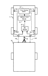
pushes the trailer. In certain situations, it is important that the trailer
moves straight
ahead or along an intended path, for example when taking a boat to water and
the
trailer needs to roll down into the water. Drivers are often confused as to
which way
to turn the vehicle steering wheel to get the desired change of direction of
the trailer.
Applying an incorrect steering angle in the vehicle may also cause the trailer
to jack-
knife and lose its course.
SUMMARY OF THE INVENTION
[0003] It is an
object of the present invention to stabilize a vehicle-trailer unit
when traveling in the reverse.
1
A02024730 2019-07-12
WO 2012/096875
PCT/US2012/020618
[0004] This object
is achieved by a method using at least one sensor
measuring a quantity that provides information about the angle between the
vehicle's
longitudinal axis and the trailer's longitudinal axis.
[0005] This can be
accomplished with at least one distance sensor generating
output information representative of the distance between the front of the
trailer and
the rear of the vehicle at a location that is laterally offset from the
location of the
trailer hitch, by establishing at least one distance value and determining the
difference between the distance value and a reference value. If the difference
exceeds a predetermined threshold, a path-correcting measure is implemented.
Such a sensor can be mounted on the rear of the vehicle or on the front of the
trailer.
[0006] Another
option is to observe a representative angle. One possibility is
to measure the rotation of the hitch, either with a sensor integrated into the
hitch or
with an imaging device. It is also possible to measure the angle between the
trailer
tongue and the longitudinal axis of the towing vehicle. A rear- and downward-
facing
sensor or camera can be placed in an elevated position on the rear of the
vehicle
and monitor the angular position of the central beam of the trailer tongue.
Similarly, a
rear-facing sensor or camera can monitor the lateral position of a reference
marker
affixed to the trailer. The marker may be anything that is optically
distinguishable
from the environment, even an existing trailer part or pattern.
[0007] Any type of
sensor capable of generating information representing a
distance or a position, such as an angular position, can be utilized to
perform the
method. Such sensors can work within the infrared spectrum, visible spectrum,
radar
spectrum, or any other suitable frequency range. Instead of electromagnetic
waves,
longitudinal material waves could be emitted and detected for distance
measurement, for instance by using ultrasound or waves in a different range of
the
2
A02024730 2019-07-12
WO 2012/096875
PCT/US2012/020618
acoustic spectrum. The sensors may simply indicate distances, detect positions
of
reference markers, generate an image like a camera or measure an angle. Thus,
the
term "sensor" as used in this specification encompasses imaging devices as
well.
[0008] If the
distance between the rear of the vehicle and the front of the
trailer during straight travel is known, one distance sensor is sufficient to
measure a
deviation caused when the trailer deviates from a straight path and moves in
an
angle relative to the vehicle. But if the distance between the rear of the
vehicle and
the front of the trailer during straight travel is not known, e.g. if the
vehicle tows
different types of trailers, then two sensors spaced laterally apart can be
used.
[0009] A
mathematically simple arrangement for the variation using two
variable distance measurements is to place the two sensors at equal distances
from
the trailer hitch, one to the left and one to the right. If they both measure
the same
distance, the trailer is traveling straight. If the signals of the two
distance sensors are
different, the trailer's path deviates from a straight line toward the side of
the shorter
measured distance between vehicle rear and trailer front.
[0010] The distance
between the vehicle and the trailer need not be known if
an angle is measured. The longitudinal vehicle axis ideally coincides with the
central
horizontal direction of a rear-facing, vehicle-mounted sensor's detection
area. If the
angle between the trailer tongue and the vehicle's longitudinal axis deviates
from
180 degrees, this deviation corresponds to the angle between the vehicle's
back and
the trailer's front.
[0011] A rear-
facing sensor mounted on the vehicle monitoring a reference
marker on the trailer may alternatively indicate the lateral deviation
distance of this
marker from a normal position. If the sensor is mounted laterally centered on
the rear
of the vehicle and the marker is at a laterally central location on the
trailer, the
3
31464-40
deviation measured is symmetric on both sides, and the deviation d divided by
the
distance between trailer hitch and marker constitutes the sine value of the
angle
between the trailer's and the vehicle's longitudinal axes.
[0012] Such a deviation can be corrected by an intervention into the
vehicle's
steering system, where the steering wheel angle is automatically corrected to
bring
vehicle and trailer into alignment with each other.
[0013] Because an angle between trailer and vehicle is sometimes what
the
driver intended, for instance when backing up into a driveway, the corrective
system
should not interfere with a driving maneuver, unless indicated by the vehicle
driver.
Such an indication can be accomplished by the driver giving a manual input
through
an interface or by the system itself after observing the driver's behavior.
[0013a] According to one aspect of the present invention, there is
provided
a method of maneuvering a vehicle-trailer unit in reverse travel comprising
the steps
of: providing a trailer having a front with a trailer tongue and a vehicle
having a rear
with a trailer hitch, the trailer tongue being connected to the trailer hitch
allowing a
horizontal swivel movement of the trailer around the hitch; providing an
electronic
processing unit having a back-up assistant module and power steering control
feature
integrated into the electronic processing unit; providing at least one
distance sensor
connected to the vehicle and configured to send information to the at least
one
electronic processing unit; providing an active power steering system in the
vehicle;
determining that the vehicle-trailer unit is backing up; measuring with said
at least
one distance sensor a quantity representing a relative position between the
vehicle
rear and the trailer front; generating output information from said at least
one distance
sensor to the electronic processing unit, wherein said output information is
representative of the distance between the front of the trailer and the rear
of the
vehicle at least at a location that is laterally offset from the location of
the trailer hitch,
by establishing at least one distance value in determining the difference
between the
distance value and a reference value; comparing the measured quantity with a
4
CA 2824736 2018-06-18
31464-40
reference value using the electronic processing unit; determining in the
electronic
processing unit an intended path of the trailer with respect to the vehicle
based upon
an input that is independent of a steering wheel for the vehicle; using the
electronic
processing unit to determine whether the trailer deviates from the intended
path with
respect to the vehicle and calculating the deviation; determining with the
electronic
processing unit whether the deviation exceeds a predetermined threshold and
using
the electronic processing unit to control; and implementing a path-correcting
measure
using the electronic processing unit to command a steering system to correct
the
course of at least one of the vehicle and the trailer while the vehicle-
trailer unit is in
reverse travel when the deviation exceeds the predetermined threshold.
[0013b] According to another aspect of the present invention, there is
provided
a system for maneuvering a vehicle-trailer unit in reverse travel comprising:
a trailer
having a front and a vehicle having a rear, the front and the rear being
connected
with a trailer hitch allowing a horizontal swivel movement of the trailer
around the
hitch, at least one first distance sensor configured to measure a quantity
representing
a relative position between the rear of the vehicle and the front of the
trailer; and a
back-up assistance module that receives information sent from the at least one
distance sensor compares the measured quantity with a reference value,
determines
from the comparison that the trailer deviates from the intended path and
calculate the
.. deviation, the back-up assistance modules then inputs an intended path of
the trailer
with respect to the vehicle that is independent of a steering wheel for the
vehicle by
sending intended path information to an electronic processing unit; the
electronic
processing unit having a power steering control feature integrated into the
electronic
processing unit, the electronic processing unit is programmed to control a
power
.. steering system of the vehicle and implement a path-correcting measure
correcting
the course of at least one of the vehicle and the trailer while the vehicle-
trailer unit is
in reverse travel when the deviation exceeds the predetermined threshold.
[0013c] According to another aspect of the present invention, there is
provided
a electronic processing unit comprising: a back-up assistant module and a
power
4a
CA 2824736 2018-06-18
31464-40
steering control feature both integrated into the electronic processing unit;
the back-
up assistant module is programmed to receive information of a measured
quantity
representative of the position of a trailer relative to a position of a
vehicle, compares
the measured quantity with a reference value and determines from the
comparison
that the trailer deviates from an intended path, wherein the intended path of
the trailer
with respect to the vehicle is input from the backup assistant module to the
electronic
processing unit and the power steering control feature then controls power
steering
system to calculate a path-correcting measure correcting the course of at
least one of
a vehicle and a trailer independent of a steering wheel for the vehicle.
[0014] Further details and aspects of the invention will become apparent
from
the description of the accompanying drawings.
BRIEF DESCRIPTION OF THE DRAWINGS
[0015] In the drawings,
[0016] Fig. 1 shows a schematic view of a vehicle towing a trailer
with two
rear-facing distance sensors mounted on the vehicle;
[0017] Fig. 2 shows such a vehicle-trailer unit in which the trailer
deviates from
a straight course;
[0018] Fig. 3 shows a vehicle-trailer unit measuring the angle between
vehicle
and trailer through measuring the lateral deviation of a marker with a camera;
[0019] Fig. 4 shows an arrangement similar to Fig. 3, where a camera
monitors
the trailer hitch; and
4b
CA 2824736 2018-06-18
A02024730 2019-07-12
WO 2012/096875
PCT/US2012/020618
[0020] Fig. 5 is an
illustration of an interface through which the vehicle driver
can control the back-up maneuver.
DETAILED DESCRIPTION OF THE DRAWINGS
[0021] In Fig. 1, a
vehicle 10 is towing a trailer 20. The trailer 20 is connected
to the vehicle 10 through trailer hitch 16, which allows the trailer to swivel
horizontally
around the vertical axis of the trailer hitch 16, which is the axis vertical
to the drawing
plane.
[0022] Two backward-
looking distance sensors 12L and 12 R are located at
the rear of the vehicle 10. They measure the distances 14L and 14R between the
rear of vehicle 10 and the front of the trailer 20 at their respective
locations left and
right of the trailer hitch 16. The information generated by the distance
sensors 12L
and 12R is sent to a back-up assistance module (BA Module) 22. The back-up
assistance module 22 compares the two pieces of information from the distance
sensors 12L and 12R.
[0023] For
simplicity purposes, it is assumed here that distances14L and 14R
are equal if the trailer 20 is in a straight line with the vehicle 10. But
this need not be
the case. Once a trailer is mounted, the driver can initiate the back-up
system to take
a "snapshot" of the prevailing distances 14L and 14R when vehicle and trailer
are
aligned along the same axis. Alternatively, the back-up assistance module can
learn
over the course of forward travel what those distances 14L and 14R are when
the
vehicle is moving straightforward. When the distances 14L and 14R differ from
each
other during straight travel, an offset distance value can be added to either
one or
both of the distances to make them equal for further calculations.
A02024730 2019-07-12
WO 2012/096875
PCT/US2012/020618
[0024] The back-up
assistance module 22 communicates with an electronic
control module 24. The electronic control module 24 is an electronic
processing unit
controlling an active power steering system 28 that is capable of actively
changing a
steering angle of front axle wheels 26-1 and 26-2 without the vehicle driver
giving a
respective input through the vehicle steering wheel. The active power steering
system 28 may also include the capability of additionally steering the rear
axle
wheels 26-3 and 26-4. The electronic control module 24 computes corrective
actions
to be taken in order to maneuver the vehicle and initiates the power steering
system
28 accordingly.
[0025] Fig. 2 shows
a situation in which the trailer 20 breaks out to the right
vehicle side ¨ making a counterclockwise turn ¨ while being pushed in the
reverse.
The trailer 20 is not aligned with the vehicle 10 at this time. As shown by
the broken
lines, the distance sensor 12L on the left side of the trailer hitch 16 will
measure a
longer distance 14L between the rear of the vehicle 10 and the front of the
trailer 20
than the distance sensor 12R on the right side of the trailer hitch 16. If the
vehicle 10
continues to travel in the direction v, the trailer will jackknife. Thus
corrective action
should be taken. For a driver who only drives a vehicle with an attached
trailer
occasionally, it is quite difficult to find the proper steering angle to bring
the trailer 20
back into alignment with the vehicle 10 as shown in Fig. 1.
[0026] The back-up
assistance module 22, receiving the information from the
rear-facing distance sensors 12L and 12R, calculates the angle between the
vehicle
and the trailer 20 from the two distances 14L and 14R. If the actual angle
between the vehicle and the trailer differs from an intended angle by an
amount
greater than a stored threshold value, the power steering system 28 applies a
corrective steering angle. The threshold value corresponds to a difference
caused by
6
A02024730 2019-07-12
WO 2012/096875
PCT/US2012/020618
a relatively small angle of at most 100. The smaller the stored threshold
value is, the
more sensitive the control will be. The exact threshold value may be
empirically
determined to best satisfy a driver's need. It could also be set by the driver
of the
respective vehicle 10.
[0027] Once the
back-up assistance module 22 has determined that the
threshold value is exceeded, the back-up assistance module 22 or the
electronic
control module 24 or both compute what the appropriate counter measure should
be,
and the electronic control module 24 controls the vehicle's power steering
system 28
to carry out those counter measures.
[0028] The vehicle
shown in Fig. 1 has an active steering system, i.e. a
steering system that can automatically change the driver-chosen steering angle
to fit
a current driving situation. For such vehicles, it is possible to add a right-
turn steering
angle to the steering angle indicated by the vehicle driver through vehicle's
steering
wheel (not shown). The power steering system 28 can change the angular
position
of the steering wheel to adopt a steering angle at the front wheels 26-1 and
26-2 and
optionally at the rear wheels 26-3 and 26-4. Alternatively, this added
steering angle
could be superimposed at the vehicle's wheel level on the steered axle or
axles,
typically the front axle, without affecting the steering wheel held by the
driver. The
added right-turn steering angle would be applied until the vehicle has made a
counter-clockwise movement sufficient to return the trailer 20 to its intended
position.
Then a slight left-turn steering angle could be added to turn the vehicle-
trailer unit
into the intended direction to continue with the back-up maneuver.
[0029] The back-up
maneuver may also be automatically performed in a
closed feedback loop to independently back up the vehicle without driver input
at all.
7
A02024730 2019-07-12
WO 2012/096875
PCT/US2012/020618
The driver can be given the possibility to override the maneuver or to disable
the
function manually.
[0030] While the
drawing shows the back-up assistance module 22 separate
from the electronic control module 24 and from the power steering system 28,
these
three modules can obviously be integrated into one or two processing units
cooperating to perform the described functions. The back-up assistance module
22
can be an after-market add-on.
[0031] Not shown is
an optional additional camera mounted at the rear of the
trailer and facing backward. Such a camera could further aid the driver of the
vehicle
if the direct view in the driving direction is obstructed while traveling in
the reverse.
[0032] The figures
are only exemplary for one of many embodiments of the
invention. For instance, it is apparent that a steering intervention could
also be
performed on a trailer with at least two axles, of which at least one is
steerable.
Likewise, if the towing vehicle has more than one steerable axle, the
intervention
could be performed on both steerable axles.
[0033] The method
of the invention does not require two distance sensors if
the distance between the rear of the vehicle at the location of the sensor and
the
front of the trailer is known for straight travel or for an intended angle
between
vehicle and trailer. Then the deviation from the known distance is compared
with a
predetermined threshold value. Naturally, this threshold value would be about
half of
the threshold value of the two-sensor embodiment discussed above.
[0034] In the
embodiment of Fig. 3, a camera 130 monitors the movement of
trailer tongue 132 for a deviation from the vehicle's longitudinal axis
indicated by the
arrow v. To this end, the camera 130, mounted on the rear of the vehicle 110,
detects a deviation of a marker 134 at a laterally central location affixed to
the trailer
8
A02024730 2019-07-12
WO 2012/096875
PCT/US2012/020618
120. This marker can be a part of the trailer tongue itself or a patch or tape
in a
contrast color. Because the trailer 120 rotates horizontally about the trailer
hitch 130,
the measured lateral distance of the marker 134 from a central position
divided by
the distance between the trailer hitch 116 and the marker 134 establishes the
sine
value of the deviation angle a between the vehicle's longitudinal axis and the
trailer's
longitudinal axis. The trailer hitch 116, being fixed with respect to both the
vehicle
110 and the trailer 120, constitutes the vertex of the deviation angle a.
[0035] The camera
130 can be preadjusted to have a central marker
reference position stored in advance to mark straight travel. But the back-up
assistance module 122 or the electronic control module 124 or both may also be
able to learn the central marker reference position over time from trip data
that have
been acquired before the vehicle 110 starts its back-up maneuver.
[0036] As shown in
Fig. 4, camera 130 can be mounted at an elevated
position approximately corresponding to the height of the passenger
compartment
roof on the rear of vehicle 110. The camera may observe marker 134 fixed on
the
front of the trailer 120 or record an image that is processed by the back-up
assistance module to calculate angle a between trailer 120 and vehicle 110.
But the
camera may alternatively be mounted in a lower position 136, as indicated with
broken lines. Such a lower mounting position may be necessary if the vehicle
is, for
instance, a pickup truck that does not allow camera 130 to be mounted in the
elevated position.
[0037] Fig. 5 shows
another embodiment, in which the driver of vehicle 210
may direct the back-up assistance module to move trailer 220 in a specific
direction
that is not necessarily in straight alignment with vehicle 210. The driver can
give an
input on the intended direction through an interface 200. The depicted
interface 200
9
A02024730 2019-07-12
WO 2012/096875
PCT/US2012/020618
comprises a monitor portion 202 and an input portion 204. The input portion
204 is
configured as a slider 206 that can be manually moved horizontally to the left
or to
the right to indicate the intended direction of the trailer 220. The slider
206 can be a
physical slider or a slider image with a touch-sensitive surface. The monitor
portion
202 shows a video stream of the movement of trailer 220 as recorded by a rear-
facing camera mounted on the vehicle 210. The bottom edge of the monitor image
shows the rear of the vehicle 210. The monitor portion 202 may further include
virtual
guides 238, 240 and 242. In the shown embodiment, virtual guide 240 indicates
the
direction of straight alignment between vehicle and trailer. Guides 238 and
242
contain distance markers to give the driver an intuitive measure of
determining the
angle between vehicle 210 and trailer 220 by being able to compare the
distance of
the trailer's right side from the vehicle 210 with the distance of the
trailer's left side
from the vehicle 210. The two virtual guides 238 and 242 may have differently
colored sections to show the driver safe, intermediate and risky relative
distances
between each side of the trailer 220 and the vehicle 210.
[0038] The broad
teachings of the disclosure can be implemented in many
ways not specifically pointed out. Accordingly, the true scope of the
disclosure is not
limited to the particular examples discussed in detail. Further modifications
become
apparent by studying the drawings, the specification, and the following
claims.