Note: Descriptions are shown in the official language in which they were submitted.
CA 02824821 2013-07-15
WO 2012/101150
PCT/EP2012/051098
1
Container Storing Freeze-Dried Biological Sample
Field of the Invention
The present invention relates to containers for holding and methods for
storing freeze-dried biological samples.
Background of the Invention
Biological samples, such as tissue or cellular extracts or lysates,
enzymes, proteins, peptides, nucleic acids, fatty acids, glycerides,
carbohydrates,
oligosaccharides and saccharides, are commonly prepared at a first site,
stored in
a container, and transported to a second site for processing. One example of
this
is in diagnostic devices and/or in DNA/RNA amplification processes. This may
require that the biological sample, which may be an enzyme such as a
polymerase or reverse transcriptase, is stored for significant periods of time
in
the container and/or subject to vibrations and/or other external forces during
transportation.
A convenient way of supplying such biological samples is to freeze-dry
the biological sample in the container prior to transportation. The container
is
typically a tube of cylindrical cross-section having a single internal
chamber.
The freeze-drying process typically involves freezing a liquid sample,
reducing
the ambient pressure, and then gradually adding enough heat to allow
sublimation of the water contained within the frozen liquid. The result is a
coagulated, dehydrated sample formed at the bottom of the container; the
container is then sealed and the biological sample (which may contain an
enzyme) is stored, and transported, in this freeze-dried state.
When the biological sample is subsequently required for processing, it
can be reconstituted by adding water to the freeze-dried material. The amount
of biological sample dissolved for a given volume of water added can be
critical;
for example, if the amount of biological sample dissolved is too small, the
strength of the solution may be insufficient.
CA 02824821 2013-07-15
WO 2012/101150
PCT/EP2012/051098
2
However, it has been observed that when the freeze-dried material is
supplied in existing tubes, some of the freeze-dried material remains un-
dissolved when water is subsequently added. This can result in a solution of
insufficient strength, as mentioned above.
Furthermore, biological samples freeze-dried, stored and transported in
this way are often of high value; accordingly, un-dissolved biological sample
is
wasteful and can increase costs.
It is an object of the present invention to at least mitigate some of the
problems of the prior art
Summary of the Invention
In accordance with a first aspect of the present invention, there is
provided a container holding a freeze-dried material comprising a biological
sample, the container comprising a chamber having an upper portion and a
lower portion, the chamber comprising a wall and the lower portion being
fluidly connected to the upper portion such that, when liquid is received at
the
upper portion, the received liquid can pass to and accumulate in the lower
portion, wherein the freeze-dried material is located in said lower portion,
and
the container comprises a physical structure protruding inwards from the wall,
the physical structure being for inhibiting the freeze-dried material from
moving
from the lower portion of the chamber to the upper portion of the chamber, and
wherein the freeze-dried material defines a first cross-section and the
physical
structure comprises a stop extending inwards from an internal wall of said
chamber, thereby defining a second cross-section, the second cross-section
having a dimension smaller than a corresponding dimension of the first cross-
section.
Since the freeze-dried material is inhibited from moving out of the lower
portion of the chamber, it can be contained within a given volume, ensuring
that
when the material is subsequently reconstituted by the insertion of a liquid
into
the container, all of the freeze-dried material can be dissolved in the
liquid,
ensuring that the reconstituted solution is of the required strength Further,
since
CA 02824821 2013-07-15
WO 2012/101150
PCT/EP2012/051098
3
a physical structure is used to prevent the movement of the freeze-dried
material, the use of a chemical, such a bonding agent, which may interfere
with
the composition of the reconstituted material can be avoided.
In addition, because the chamber has upper and lower portions, with the
freeze-dried material being kept in the lower chamber, the freeze-dried
material
can be kept away from any seal applied to the upper portion; this avoids the
contamination which may result from such contact.
Alternatively or additionally, in some embodiments the freeze-dried
material defines a first cross-section and the physical structure comprises a
stop
extending inwards from an internal wall of said chamber, the stop defining a
second cross-section, the second cross-section having a dimension smaller than
a corresponding dimension of the first cross-section. The stop may define a
boundary between the upper portion of the chamber and the lower portion of the
chamber. The stop may thus define a volume of the container within which the
freeze-dried material is maintained. In some embodiments, the stop comprises a
collar that is integrally formed with the chamber. Alternatively, the stop may
comprise a movable insert, the movable insert being movable within said
chamber, thereby varying the extent or position of said boundary. Using a
movable collar enables the volume of the chamber within which the freeze-dried
material is maintained to be varied
Preferably, the container comprises a physical structure comprising a
textured surface, which further increases the bonding surface area between the
freeze-dried biological sample and the chamber.
The container may be of a plastics material.
The chamber may have a substantially circular cross-section.
Preferably, the upper portion extends from a first end of the container,
and the container comprises a seal at the first end.
In accordance with a second aspect of the present invention, there is
provided an apparatus storing a freeze-dried material comprising a biological
sample, the apparatus comprising; a plurality of containers according to the
first
aspect of the invention; and a base plate supporting the plurality of
containers.
CA 02824821 2013-07-15
WO 2012/101150
PCT/EP2012/051098
4
The apparatus may comprise a base plate of a plastics material.
In accordance with a third aspect of the present invention, there is
provided a method of storing a biological sample, comprising: providing a
container, the container comprising a chamber having an upper portion and a
lower portion, the chamber comprising a wall and the lower portion being
fluidly connected to the upper portion such that, when liquid is received at
the
upper portion, the received liquid can pass to and accumulate in the lower
portion; inserting a material containing a biological sample into the chamber
and accumulating the liquid biological sample in the lower portion of the
chamber; and performing a freeze-drying process on the material, whereby a
freeze-dried material comprising said biological sample is formed in the lower
portion, wherein the container comprises a physical structure protruding
inwards
from the wall, the physical structure being for inhibiting the freeze-dried
material from moving out of the lower portion., and wherein the freeze-dried
material defines a first cross-section and the physical structure comprises a
stop
extending inwards from an internal wall of said chamber, thereby defining a
second cross-section, the second cross-section having a dimension smaller than
a corresponding dimension of the first cross-section.
In accordance with a fourth aspect of the present invention, there is
provided a container holding a freeze-dried biological sample, the container
comprising a chamber having an upper portion and a lower portion, the lower
portion comprising a wall and being fluidly connected to the upper portion
such
that, when liquid is received at the upper portion, the received liquid can
pass to
and accumulate in the lower portion, wherein the freeze-dried biological
sample
is located in said lower portion, and the wall comprises a rough surface to
which
the freeze-dried biological sample is bonded, whereby the freeze-dried
biological sample is prevented from moving from the lower portion to the upper
portion.
A further aspect of the invention provides the use of the container of the
first aspect, and/or the array of the second aspect, and/or the container of
the
fourth aspect for processing a biological sample.
81772558
4a
In accordance with a further aspect of the present invention, there is
provided a container
holding a freeze-dried material comprising a biological sample, the container
comprising a chamber
having an upper portion and a lower portion, the chamber comprising a wall and
the lower portion
being fluidly connected to the upper portion such that, when liquid is
received at the upper portion,
the received liquid passes to and accumulates in the lower portion, wherein
the freeze-dried
material is located in said lower portion, and the container comprises a
physical structure protruding
inwards from the wall, the physical structure being for inhibiting the freeze-
dried material from
moving from the lower portion of the chamber to the upper portion of the
chamber, wherein the
freeze-dried material defines a first cross-section and the physical structure
comprises a stop
extending inwards from an internal wall of said chamber, thereby defining a
second cross-section,
the second cross-section having a dimension smaller than a corresponding
dimension of the first
cross-section, and wherein the stop defines a boundary between the upper
portion of the chamber
and the lower portion of the chamber, wherein the stop comprises a movable
insert, the movable
insert being movable within said chamber, thereby to vary said boundary.
In accordance with a further aspect of the present invention, there is
provided an apparatus
storing a freeze-dried material comprising a biological sample, the apparatus
comprising: a
plurality of containers as described above; and a base plate supporting the
plurality of containers.
In accordance with a further aspect of the present invention, there is
provided a method of
storing a biological sample, comprising: providing a container, the container
comprising a
chamber having an upper portion and a lower portion, the chamber having a wall
and the lower
portion and being fluidly connected to the upper portion such that, when
liquid is received at the
upper portion, the received liquid can passes to and accumulates in the lower
portion; inserting a
material containing a biological sample into the chamber and accumulating the
material in the
lower portion of the chamber; and performing a freeze-drying process on the
material, whereby a
freeze-dried material comprising said biological sample is formed in the lower
portion, wherein
the container comprises a physical structure protruding inwards from the wall,
the physical
structure being for inhibiting the freeze-dried material from moving from the
lower portion to the
upper portion, wherein the freeze-dried material defines a first cross-section
and the physical
structure comprises a stop extending inwards from an internal wall of said
chamber, thereby
defining a second cross-section, the second cross-section having a dimension
smaller than a
corresponding dimension of the first cross-section, and wherein the stop
defines a boundary
CA 2824821 2019-07-02
=
81772558
4b
between the upper portion of the chamber and the lower portion of the chamber,
wherein the stop
comprises a movable insert, the movable insert being movable within said
chamber, thereby to
vary said boundary.
in accordance with a further aspect of the present invention, there is
provided use of a
container or apparatus as described above, for processing a freeze-dried
biological sample.
CA 2824821 2019-07-02
81772558
Further features and advantages of the invention will become apparent
from the following description of preferred embodiments of the invention,
given
by way of example only, which is made with reference to the accompanying
drawings.
5
Brief Descri ption of the Drawings
Figure 1 shows a cross-section view of a container holding a freeze-dried
material;
Figure 2a shows a perspective view of another container for holding a
freeze-dried material;
Figure 2b shows orthographic projections of the container of Figure 2a
holding a freeze-dried material;
Figure 3a shows a perspective view of a container for holding a freeze-
dried material comprising a biological sample according to a first embodiment
of the present invention;
Figure 3b shows orthographic projections of a container holding a
freeze-dried material comprising a biological sample according the first
embodiment;
Figure 4 shows a cross-section view of a container for holding a freeze-
dried material comprising a biological sample according to a second
embodiment of the present invention;
Figure 5a shows a perspective view of an array of containers for holding
a freeze-dried material comprising a biological sample according to
embodiments of the present invention;
Figure 5b shows a perspective view of an array of containers for holding
a freeze-dried material comprising a biological sample according to
embodiments of the present invention;
Figure 5c shows a plan view of an array of containers for holding a
freeze-dried material comprising a biological sample according to embodiments
of the present invention;
CA 2824821 2018-07-25
CA 02824821 2013-07-15
WO 2012/101150
PCT/EP2012/051098
6
Figure 5d shows a side view of an array of containers for holding freeze-
dried biological samples according to embodiments of the present invention;
Figure 6a shows a perspective view of an alternative arrangement in
which there is no physical structure holding a freeze-dried material
comprising a
biological sample; and
Figure 6b shows an orthographic projection of an alternative
arrangement in which there is no physical structure holding a freeze-dried
material comprising a biological sample.
Detailed Description of the Invention
In Figure 1, a container in the form of a tube 100 is provided, the tube
100 comprising a chamber 102 having a wall 104, an upper portion 106, and a
lower portion 108, the lower portion 106 holding a freeze-dried material
comprising a biological sample; the freeze-dried material is hereinafter
referred
to as a cake 110. Typically, the cake 110 is in a disc-shaped form. The tube
100
comprises a physical structure 112 to inhibit movement of the freeze-dried
biological sample from the lower portion 108 of the chamber 102 to the upper
portion 106 of the chamber 102. The tube 100 comprises a first end 114, which
may initially be open in order to enable insertion of the material prior to
freeze-
drying, and subsequently closed with a seal (not shown).
The external dimensions of the tube 100 may be fixed at an industry
standard for ease of handling, for example, automated handling by existing
laboratory equipment. Typically, the tube 100 is 8 mm in diameter and 18.3 mm
long. Typically, the internal dimensions of the tube are large enough in both
diameter and depth to accommodate standard dispensing tools, for example
pipetting needles in automated dispensing systems; this has the advantage that
there is no need for readjustment or calibration of existing tools.
The biological sample may comprise an enzyme, such as a polymerase,
reverse transcriptase or any other enzyme, blood, tissue, serum or any other
biological substance.
CA 02824821 2013-07-15
WO 2012/101150
PCT/EP2012/051098
7
In Figures 2a and 2b, a tube 100a is provided in which a physical
structure 112 in the form of protrusions, herein referred to as fins 200,
extends
inwards from the wall 104a of the chamber 102a, and extends longitudinally
along a direction parallel to the axis L of the tube 100a.
Figure 2a shows the tube 100a prior to insertion of the biological sample.
The tube 100a is initially open at a first end 114a, from which the upper
portion
106a extends. During preparation, a material (typically in liquid form)
containing the biological sample, is inserted into the chamber 102a via the
first
end 114a and allowed to accumulate in the lower portion 108a. A freeze-drying
process is then performed so that the material is dehydrated in the lower
portion
108a, and in and around the spaces between the fins 200, thereby forming the
cake 110 shown in Figure 2b. The freeze-drying process bonds the cake 110 to
the fins 200. The additional contact area between the cake 110 and the
internal
surface of the tube 100a provided by the fins 200 increases the strength of
the
bond between the cake 110 and the tube 100a, thereby increasing the ability of
the tube 100a to hold the freeze-dried cake 110 in place. Further, the shape
of
the freeze-dried cake 110 comprises recesses into which the fins 200 fit. This
interlocking fit between the freeze-dried cake 110 and the fins 200 prevents
rotation of the freeze-dried cake 110 about the central longitudinal axis L of
the
tube 100a, further reducing the likelihood of detachment.
The first end 114a may be sealed, subsequent to insertion of the material
that is to be freeze-dried with a seal (not shown). The seal, which may be an
impermeable seal, may be made of flexible foil, polymer laminate and/or any
other suitable material, and may be held in place with a permanent or semi-
permanent adhesive. When the freeze-dried material is required for subsequent
processing, the seal may be removed, or penetrated by a dispensing needle, for
example. Since the cake 110 is kept in the lower portion 108a of the chamber
102a, it is kept away from the seal. This is advantageous because contact with
the seal can cause contamination of the freeze-dried biological sample.
When the biological sample is subsequently reconstituted, by inserting,
for example, water into the tube 100a, provided that sufficient volume of
water
CA 02824821 2013-07-15
WO 2012/101150
PCT/EP2012/051098
8
is inserted to fill the lower portion 108b, it can be ensured that
substantially all
of the cake 110 is dissolved in the water.
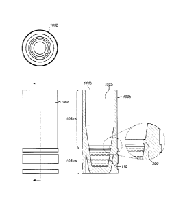
Figures 3a and 3b show an embodiment of the present invention in
which the tube 100b comprises a stop in the form of a collar 300 extending
inwards from the wall 104b of the chamber 102b. Figure 3a shows the tube
100b prior to insertion of the biological sample. As was described above in
relation to Figures 2a and 2b, the tube 100b is initially open at a first end
114b,
from which the upper portion 106b extends.
During preparation, a material (typically in liquid form) containing the
biological sample, is inserted into the chamber 102b via the first end 114b
and
allowed to accumulate in the lower portion 108b. A freeze-drying process is
then performed so that the material coagulates in the lower portion108b, below
the collar 300, thereby forming the cake 110 shown in Figure 3b, the cake 110
being bonded to the wall 104b of the chamber102b.
The cake 110 is formed in the lower portion 108b below the collar 300
such that it has a larger external diameter than the internal diameter of the
collar
300. In this way, the cake 110 is inhibited from moving through the aperture
formed by the collar 300 and is kept in the lower portion 108b of the tube
100b.
Thus, the position of the collar 300 defines the boundary between the upper
portion 106b and the lower portion 108b, and the volume of the lower portion
108b within which the cake 110 is held. When the biological sample is
subsequently reconstituted, by inserting, for example, water into the tube
100b,
provided that sufficient volume of water is inserted to fill the tube 100b up
to or
higher than the level of the collar 300, it can be ensured that substantially
all of
the cake 110 is dissolved in the water.
The first end 114b may be sealed, subsequent to insertion of the material
that is to be freeze-dried with a seal as described above in relation to
Figures 2a
and 2b.
Typically, the collar 300 comprises a substantially semicircular rib with
a radius of 0.24 mm running parallel to, and 4.2 mm above, the base of the
chamber 102b of the tube 100b.
CA 02824821 2013-07-15
WO 2012/101150
PCT/EP2012/051098
9
The collar 300 described in this example is integrally formed with the
wall 104b of the tube 100b. However, in some embodiments, a collar is
provided by a separate component which is inserted into the tube 100b. This
separate component may take the form of a ring, and may be held in place by an
interference fit. The position separate component within the tube may be
adjustable, allowing adjustment of the boundary between the upper portion 106b
and the lower portion 108b of the chamber 102b and, therefore, the volume of
the lower portion 108b.
In one embodiment, shown in Figure 4, rather than using a physical
structure 112 to inhibit movement of the cake, the surface of the internal
walls
104c of the lower portion 108c of a tube 100c comprises a textured portion 400
to improve the adhesion of the freeze-dried cake 110 onto the internal walls
104c of the tube 100c. The textured portion 400 effectively increases the
contact area between the freeze-dried cake 110 and the wall 104 of the tube
100c. The textured portion 400 may comprise a regular pattern of surface
features, such as a knurled surface, or may comprise a rough surface with
randomly varying surface features. The additional adhesion provided by the
increased surface area increases the force required to detach the cake 110
from
the tube 100c and, therefore, reduces the likelihood of detachment. The cake
110 may be formed using a freeze-drying process as described above in relation
to figures 2a to 3b.
In this embodiment no other physical structures 112 are present in the
lower portion 108c of the tube 100c and the freeze-dried cake 110 is held in
place solely by adhesion to the interior walls of the tube 100c. However, it
will
be understood that the textured portion 400 may be used in combination with
any of the physical structures 200, 300 in the embodiments described above, or
indeed with any other form of physical structure for inhibiting the freeze-
dried
material from moving from the lower portion 108 of the chamber 102 to the
upper portion 106 of the chamber 102. For example, the fins 200 described
above in relation to figures 2a and 2b may themselves be textured in order to
further increase the strength of the bond between the cake and the fins 200;
in
CA 02824821 2013-07-15
WO 2012/101150
PCT/EP2012/051098
the embodiment described above in relation to figures 3a and 3b, the textured
portion could be positioned in the lower portion 108b below the collar 300.
Any of the tubes 100 described above may be used as individual
containers or may be arranged, as in Figure 5a, in an array 500 for subsequent
5 parallel or batch processing. In the embodiment shown, the tubes 100 are
arranged in an 8><12 rectangular array on a base plate 502 with external
dimensions corresponding to the SBS industrial standard footprint. Typically,
the base plate 502 is 127.76 mm long and 85.48 mm wide.
The array 500 may comprise an impermeable seal 504, which covers the
10 open first ends 114 of each of the tubes 100 as shown in Figure 5b. In
this
example, the seal 504 may comprise a continuous sheet in contact with each of
the tubes 100; alternatively, the tubes could be individually sealed, as
described
above. The seal 504 may be held in place with a permanent or semi-permanent
adhesive. The seal 504 may be made from a flexible foil/polymer laminate or
any other suitable material. The seal 504 may be penetrated by a dispensing
needle or removed from the tubes 100 prior to use by breaking the semi-
permanent adhesive bond.
The base plate 502 of the array 500 may comprise identifying grid-
coordinates 506, as shown in Figure 5c, correlating with the positions of each
of
the tubes 100 to enable identification and addressing of individual samples.
The base plate 502 of the array 500 may comprise an identification tag
508 comprising coded computer readable identification inforniation, as shown
in
Figure 5d. The tag 508 may comprise a barcode 508a that can be scanned and
compared with a database of sample identification codes; other types of tag
508
may be used, for example an RFID tag.
Crush ribs may be added to the external walls of the tube 100 to increase
the structural strength of the tube 100 without increasing the overall
external
dimensions of the tube 100.
The tube 100 and array 500 may comprise a chemically and biologically
inert material that can withstand temperatures in the range -40 C to 50 C or
more. Suitable materials include polycarbonate, polystyrene, or polypropylene.
CA 02824821 2013-07-15
WO 2012/101150
PCT/EP2012/051098
11
The tube 100 may be manufactured using an injection moulding process or by
any other appropriate method. The array 500 may be manufactured as a single
component using an injection moulding process or the tubes 100 and the base
plate 502 may be manufactured as discrete parts and assembled and fixed
together by, for example, an ultrasonic weld or by any other appropriate
method.
Figures 6a and 6b show an alternative tube 100d in which no physical
structure 112 inhibits movement of the cake 110. In this arrangement, the tube
has a chamber 102d having a volume arranged to be significantly lower than the
external volume of a tube 100d but not significantly larger than the volume of
liquid required to reconstitute the cake 110. This allows the external
dimensions
of the tube 100d to be arranged to, for example, satisfy an industry standard,
but
the internal volume 102d to be reduced, thereby reducing the volume within
which the cake 110 can move. Typically, while the external length of the tube
100d remains at 18.3 mm, the internal depth of the tube 100d is reduced to 6.9
mm. The effect of this is to reduce the risk of the freeze-dried cake 110
occupying a volume that is not subsequently filled with a liquid during
subsequent reconstitution of the biological material (for example, an enzyme).
It will be understood that this arrangement may be used as an individual
container or in an array 500, as described above.
Embodiments of the present invention are typically to be used for DNA
or RNA amplification procedures such as polymerase chain reaction (PCR) that
have common application in a variety of fields including molecular biology,
medicine and forensic science.
The above embodiments are to be understood as illustrative examples of
the invention. Further embodiments of the invention are envisaged. For
example, although in the embodiment described above with reference to figures
2a and 2b, there is no physical indication of a boundary between the lower
portion 108b and the upper portion 106b, in some embodiments an indication of
the boundary may be provided, for example in the form of a mark or protrusion
on the wall 104b of the chamber 114b.
CA 02824821 2013-07-15
WO 2012/101150
PCT/EP2012/051098
12
It is to be understood that any feature described in relation to any one
embodiment may be used alone, or in combination with other features described,
and may also be used in combination with one or more features of any other of
the embodiments, or any combination of any other of the embodiments.
Furthermore, equivalents and modifications not described above may also be
employed without departing from the scope of the invention, which is defined
in
the accompanying claims.