Note: Descriptions are shown in the official language in which they were submitted.
SCAFFOLD APPARATUS, METHOD AND SYSTEM
FIELD OF THE INVENTION
This invention relates to modular scaffolding systems that are erected as
impermanent
structures to support platforms. Scaffolding is used, inter alia, in the
industrial, commercial,
petro-chemical, power source, general industry and residential construction
markets.
BACKGROUND
In 2008, the Bureau of Labor Statistics' Census of Fatal Occupational Injuries
(CF01)
reported 88 fatalities occurred in the year 2007 related to the use of
scaffolds and many more
injuries. Twenty-seven percent (27%) of the fatalities and many of the
injuries involved falls
off of welded frame scaffolds over 25 feet high during the installation of the
scaffolds.
Safety officials recommend that scaffolding falls be pre-empted through the
use of sequential
erection techniques. This involves installing guardrails and standards at
regular distances
along the scaffold such that the exposed platform edge is not greater than a
bay length
between intervals. The use of safety harnesses or belts tethered to guardrails
during the
erection process is also a recommended safety practice. However, the use of
safety harnesses
to deter fall injuries during scaffold erection is quite limited due to the
components used in
conventional scaffolds. The nature and design of conventional scaffold
components, as
described herein, disadvantageously do not allow the effective use of safety
harnesses during
the erection process.
Tube and coupler scaffolds are so-named because they are built from tubing
connected by coupling devices. Due to their strength, they are frequently used
where heavy
loads need to be carried, or where multiple platforms must reach several
stories high.
Components of scaffolds include vertical standards having coupling rings or
rosettes,
horizontal components such as ledgers and guardrails coupled to the coupling
rings or
rosettes, footings, decks/platforms and diagonal braces. Their versatility,
which enables them
to be assembled in multiple directions in a variety of settings, also makes
them difficult to
build correctly.
1
CA 2824886 2018-05-31
CA 02824886 2013-07-16
WO 2012/102881 PCT/US2012/021346
Conventional scaffolding systems have various components. Figure 1 illustrates
a
supported scaffold 100 consisting of one or more platforms supported by rigid
support
members such as poles, tubes, beams, brackets, posts, frames and the like.
More specifically,
the supported scaffold 100 includes the following components: deck/platform
101, horizontal
members, or ledgers 102, vertical standards 103. Additional components include
diagonal
braces to increase the stiffness and rigidity of the scaffold 100.
Figure 2 is an illustration of a vertical standard 103. Vertical standards are
typically
cylindrical tubes 200 comprised of hot-dip galvanized steel or aluminum. A
collar with an
expanded or reduced diameter or a spigot at either or both ends of the
vertical standard
facilitates the joining of vertical standards from end to end. Rosettes 201
arc positioned and
then welded or otherwise attached along the tubes providing connections for
horizontal
members and diagonal braces. The vertical standard can have from one to 8 or
more rosettes
placed along the tubing using a predetermined spacing between rosettes, for
example, about
every 20 inches.
Figure 3 illustrates a ledger 102. A ledger is a horizontal member that serves
as both a
guardrail and bracing element. The ledger 102 is comprised of tubing 300,
heads 301 and
wedges 302. Ledgers 102 are available in different lengths, depending on the
scaffolding bay
length, deck type and load. It is the conventional manner in which these
ledgers are coupled
to vertical standards that contribute to scaffolding falls as further
described herein. Once the
tubing on a level is installed, decks or platforms 101 made of, e.g., hot-dip
galvanized steel,
aluminum, wood or an aluminum frame with plywood board are installed to allow
workers to
traverse the scaffold 100 and install the guardrails (e.g., ledgers 102).
Referring now to Figure 4, wedge 302 is shown being hammered into the slot or
gap
of head 301 at the end of a ledger 102 so as to couple it to the rosette 201
of the vertical
standard 200. This must be done by a worker first at the proximate end of the
ledger 102 and
then at the distal end of the ledger 102. However, as the proximate end of the
ledger 102 is
being coupled to the vertical standard using the wedge 302, the distal end of
the ledger 102 is
free and uncoupled, that is, until the worker can traverse the platform to the
distal end of the
ledger 102 and hammer in a wedge 302 at the distal end. During this time, the
distal end of
the ledger 102 remains uncoupled from the vertical standard. Hence, if the
installer is
harnessed to the ledger 102 and the scaffold tilts toward the uncoupled,
distal end, the
installer may tumble down the platform and the safety harness will exit the
uncoupled end of
the ledger, providing no measure of safety to the installer.
A conventional rosette 500, as seen in Figure 5, has a central aperture 503 to
receive
2
CA 02824886 2013-07-16
WO 2012/102881 PCT/US2012/021346
the vertical tubing, four small openings 501A-D to facilitate right-angled
connections and
four larger openings 502 A-D to facilitate connections at certain plurality of
angles.
Typically, a vertically and horizontally slotted head 504 coupled to the end
of a ledger is
positioned with respect to the rosette 500 such that the horizontal slot of
the head 504 is
.. positioned over and under the rosette 500 and the vertical slot of the head
is aligned with an
aperture of the rosette 500. A wedge 302 is then hammered into the vertical
slot (or gap) to
couple the ledger 102 via the head 504 to the vertical standard 103 via the
rosette 500 using,
inter alia, frictional force. Note that, disadvantageously, until the wedge
302 is installed,
there is significant play between the rosette 500 and head of a horizontal
member giving rise
to safety concerns. Furthermore, once installed, wedges often work free when
workers
traverse the platform. When these wedges work free, the scaffold can become
unstable and
collapse. Further, even if the scaffold does not collapse, steel wedges,
which, as seen in the
Figure, are not integrated into the head or the ledger, can fall from the
scaffold injuring
workers below.
What is desired is a scaffolding apparatus that is configured to couple each
end of a
ledger (also referred to herein as a horizontal member) to a vertical standard
(also referred to
herein as a vertical member) simultaneously, and which has an wedge assembly
mechanism
that allows a single installer to insert and lock wedges at both ends of the
horizontal member
substantially simultaneously to the vertical standard. The invention provides
such an
apparatus.
SUMMARY
The invention comprises a scaffold apparatus that overcomes the safety,
rigidity, and
labor issues inherent in conventional scaffold systems. The ring, collar,
rosette or component
with similar functionality, is referred to as a rosette with respect to the
invention; the vertical
standard or component with similar functionality, is referred to as a vertical
member with
respect to the invention and the ledger, guardrail or component with similar
functionality is
referred to as a horizontal member. The use of the foregoing terms is not to
be interpreted as
limiting the scope of the invention.
As noted herein, components of the invention include at least one horizontal
member
and a wedge head attached to each end of the horizontal member. A wedge
assembly is
located partially within the horizontal member and each wedge head, each wedge
assembly
having a handle coupled to a wedge portion for coupling the wedge head to a
vertical
3
member.
A rosette having a set of radially arranged cut-outs, the vertical member
affixed in
coaxial alignment with the rosette, is provided to receive the wedge head
having mating
elements corresponding to the radially arranged cut-outs of the rosette,
wherein, when the
mating elements of the wedge head are received in the radially arranged cut-
outs of the
rosette, the wedge assembly, when actuated, causes the wedge portion to
rigidly couple the
horizontal member to the rosette. The handle of the wedge assembly is
springably coupled to
the wedge head, said handle, when actuated, being operable to cause the wedge
portion to
partially extend or retract into the wedge head. A rod or cable within the
horizontal member,
couples the first handle of the wedge assembly to the second handle at the
other end of the
horizontal member, causing it to simultaneously engage or disengage the wedge
at the other
end of the horizontal member.
Each of the wedge heads have at least one or a plurality of mating elements or
prongs
dimensioned to fit within a grid of apertures formed in the rosette, the wedge
head having an
.. opening or slot through which the wedge portion wholly or partially extends
to lock the
wedge head, and hence, the horizontal member to the rosette and wholly or
partially retracts
to unlock the wedge head, and hence, the horizontal member from the rosette.
According to an aspect of the present invention there is provided an apparatus
for
coupling a horizontal member to a vertical member of a scaffold, comprising:
a horizontal member and a first wedge head coupled to a first end of the
horizontal
member; and
a first wedge assembly partially within the first wedge head, the first wedge
assembly
pivotably coupled to the first wedge head, the first wedge assembly further
comprising a first
handle communicably coupled via a first wedge linkage assembly to a first
wedge, said first
handle, when actuated, operable to cause the first wedge to fully or partially
extend or retract
into the first wedge head, such that said first wedge maintains its extended
or retracted position
until said handle is further actuated.
According to another aspect of the present invention there is provided a
method for
coupling a horizontal member to a vertical member of a scaffold, comprising
the steps of
4
CA 2824886 2018-05-31
providing a horizontal member having a wedge head coupled to each end of the
horizontal member, the wedge heads each having therein a wedge assembly
partially within
the wedge head, each wedge assembly pivotably coupled to its respective wedge
head, each
wedge assembly further comprising a handle communicably coupled via a wedge
linkage
assembly to a wedge, the wedge linkage assemblies being operatively coupled
via a cam
mechanism within the horizontal member; and
disengaging the handle causing its wedge head to retract into its respective
wedge
head, wherein if the handle is partially actuated, the wedge maintains its
extended or retracted
position until said handle is further actuated.
To those skilled in the art to which this invention relates, many changes in
construction and widely differing embodiments and applications of the
invention will suggest
themselves without departing from the scope of the invention as defined herein
and in the
appended claims. The disclosures and the descriptions herein are purely
illustrative and are
not intended to be in any sense limiting.
DESCRIPTION OF THE DRAWINGS
A more complete understanding of the invention may be obtained by reference to
the
following Detailed Description, when taken in conjunction with the
accompanying Drawings,
wherein:
Figure 1 illustrates a scaffold structure;
Figure 2 illustrates a vertical standard;
Figure 3 illustrates a conventional ledger with unsecured wedges;
Figure 4 illustrates the installation of an unsecured wedge into a
conventional ledger
head;
Figure 5 illustrates a rosette and conventional head and wedge;
4a
CA 2824886 2018-05-31
CA 02824886 2013-07-16
WO 2012/102881 PCT/1JS2012/021346
Figure 6 is a rosette used with an embodiment of the invention;
Figure 7 is an embodiment of a vertical member of the invention;
Figure 8 is a side view of a first embodiment of the wedge head of the
invention;
Figure 9A is a first perspective view of a first embodiment of the wedge head
of the
invention;
Figure 9B is a second perspective view of a first embodiment of the wedge head
of
the invention;
Figure 10 is a cam mechanism used in the first embodiment;
Figure 11 is a cutaway side view of a second embodiment being a horizontal
member
in the unlocked position; and
Figure 12 is a cutaway side view of a second embodiment being a horizontal
member
in the locked position.
DETAILED DESCRIPTION
The invention comprises a scaffold system, and components thereof, that
overcomes
the safety, rigidity, and labor issues inherent in conventional scaffold
systems. The ring,
collar, rosette or component with similar functionality, is referred to as a
rosette with respect
to the invention; the vertical standard or component with similar
functionality, is referred to
as a vertical member with respect to the invention and the ledger, guardrail
or component
with similar functionality is referred to as a horizontal member. The use of
the foregoing
terms is not to be interpreted as limiting the scope of the invention.
As noted herein, components of the invention include at least one horizontal
member
which horizontal member preferably has a wedge head at each end thereof, alone
or in
combination with at least one vertical member including at least one rosette
affixed in coaxial
alignment thereon, the rosette having apertures for receiving mating elements
or prongs of an
wedge head (which may be a separate component of the horizontal member, or an
integrated
portion at the end of the horizontal member), a wedge assembly within the
wedge head and
horizontal member, the wedge assembly having a separate handle and wedge
portion or
integrated handle and wedge portion, the wedge assembly at an end of the
horizontal member
being responsively coupled to a wedge assembly at the other end of a
horizontal member
using a rod or cable or other transmission means. Each wedge head may further
include one
or a plurality of prongs dimensioned to fit within a grid of apertures formed
in the rosette.
The wedge head has an opening or slot through which the wedge portion extends
wholly or
5
CA 02824886 2013-07-16
WO 2012/102881 PCT/US2012/021346
partially out of the wedge head to lock the wedge head when activated by a
handle, operable
to couple the horizontal member to the rosette
An aspect of the invention is a joint for use in coupling a horizontal member
to a
vertical member having a rosette with a set of radially arranged cut-outs, a
horizontal member
further comprising a hollow tube having contained therein a wedge assembly,
the wedge
assembly having a wedge portion at the end thereof which is wholly or
partially extendable
and retractable into a hollow tube or cavity of a wedge head and/or horizontal
member. The
wedge head, located at the end of the horizontal member, has mating elements
corresponding
to the radially arranged cut-outs of the rosette. When the mating elements of
the wedge head
or the horizontal member are received in the radially arranged cut-outs of the
rosette and the
wedge assembly is actuated using, e.g., a handle, causes the wedge portion to
firmly join or
couple the wedge head or horizontal member to the rosette.
Referring now to Figure 6, the top view of one embodiment of a rosette 600 of
the
invention is shown. An embodiment of rosette 600 is circular in shape and has
a breadth or
extent. Such breadth or extent may be any measure appropriate to allow the
wedge head to
engage the rosette 600 as more fully described herein. Rosette 600 has a
central aperture 601
or cut-out in a substantially circular shape dimensioned to receive the
vertical tubing of the
vertical member. In another aspect, such central aperture or cut-out may be
any shape that
corresponds to the cross-sectional shape of a vertical member. Once placed on
the vertical
tubing, rosette 600 can thus be welded or otherwise attached in a co-axial
alignment with the
vertical tubing of the vertical member. A plurality of rosettes can thus be
positioned and
affixed along the length of the vertical tubing. Between the outer
circumference of rosette
600 and the outer circumference of the central aperture 601 are a plurality of
radially
arranged cut-outs 602 for receiving prongs of at least one wedge head as
further described
herein. The grid arrangement of the radially arranged cut-outs 602 allow for
multiple
arrangements of horizontal members to the vertical member via rosette 600. As
seen in
Figure 6, eight (8) radially arranged cut-outs are shown, although a different
number of
radially arranged cut-outs can be arranged on rosette 600. In an embodiment of
the
invention, the radially arranged cut-outs 602 generally comprise trapezoids
with inner and
outer edges having circular arcs of concentric circles of different radii. The
intersections of
the line segments and arcs can be filleted, comprising a concave easing of the
interior corners
to reduce stress concentration. On a portion of, and further cut out from, the
inner and outer
edges of such trapezoids are arc shaped notches comprising a portion of a
circle centered on
the trapezoid. The edges of intersection of each of the upper and lower
surfaces of the rosette
6
CA 02824886 2013-07-16
WO 2012/102881 PCT/US2012/021346
with the vertical, interior walls of the rosette can be rounded, beveled or
chamfered. The
radially arranged cut-outs 602 are dimensioned to receive vertical prongs of
the wedge head.
Stated otherwise, the vertical member includes at least one rosette having a
set of radially
arranged cut-outs, the vertical member affixed in coaxial alignment with the
rosette, the cut-
outs to receive the wedge head having mating elements corresponding to the
radially
arranged cut-outs of the rosette, wherein, when the mating elements of the
wedge head are
received in the radially arranged cut-outs of the rosette, the wedge assembly,
when actuated,
causes the wedge portion to rigidly couple the horizontal member to the
rosette.
Figure 7 is one embodiment of a vertical member 700 of the invention having a
plurality of rosettes 600 positioned and affixed in coaxial alignment on
vertical tubing 701.
Figure 8 is a side view 800 of a first embodiment of the wedge head of the
invention
wherein the handle and wedge assembly on at least one end of horizontal member
810 are
integrated into the wedge head. Such wedge head is shown coupled to rosette
801. Wedge
head 802 includes an optional finger bar (not seen) which is attached to, and
extends from, a
top side of wedge head 802 to a position on outer surface of horizontal member
810. The
finger bar strengthens the attachment of wedge head 801 to horizontal member
810 and also
protects handle 812 from damage. Rotatably integrated into wedge head 802 is a
wedge
assembly which includes wedge 818 which is biased by spring 803 wound around
pin 804,
handle 812 and a handle linkage assembly 806 which is rotatably coupled to
wedge head 802
with pin 808 which is seated in openings in the apositioned inside walls of
wedge head 802.
Spring 803 includes a transverse portion on the end in contact with a top
surface of wedge
818 so as to both guide wedge 818 and apply downward pressure on wedge 818,
which
downward pressure is translated from pressure on wedge 818 to rosette 801.
Support 814
which is integrated into wedge head 802 provides an upward force against the
bottom surface
of wedge 818 which counteracts the downward force of spring 803 on the top
surface of
wedge 818.
A first extension on which pressure is applied by a user to lock or unlock the
invention to a rosette is handle 812. An integrated offset angled extension
from handle 812 is
the handle linkage assembly 806. The handle linkage assembly 806 has a
plurality of
apertures for coupling to components such as the wedge and rod and to wedge
head 802.
Handle 812 and handle linkage assembly 806 are rotatably coupled to wedge head
802 with
pin 805 and are movable along an arc of motion via guide 813 and pin 807. The
first end of
rod 809 is rotatably coupled to handle linkage assembly 806 with pin 811. The
second end
(not seen) of rod 809 is coupled to a second wedge at the distal end of
horizontal member
7
CA 02824886 2013-07-16
WO 2012/102881 PCT/US2012/021346
810.
In a second embodiment as more fully described below, rod 809 and its related
mechanisms are replaced with a cable which couples a first handle linkage
assembly in a
wedge head at one end of a horizontal member to a wedge head at a second end
of the
horizontal member. The tension of the cable operates to bias the wedges at
each end of the
horizontal member simultaneously in either the extended (locked) or retracted
(unlocked)
position depending on the position of their respective handles. As noted
below, the cable can
be threaded around internal pins, wheels and axles and biased with, inter
alia, springs.
In operation, the wedge head 802 is at one end of the horizontal member 810.
The
wedge head 802 has handle 812 pivotably coupled to the wedge head 802 with the
end of the
handle 812 internal to the wedge head 802 being integrated at a first end to
the handle linkage
assembly 806. The handle linkage assembly 806 is pivotably coupled to the
wedge head 802,
a distal end of a wedge 818 being rotatably coupled with a pin 808 or similar
mechanism to
the handle linkage assembly 806 at a mid-section thereof. The wedge 818 is
biased by a
transverse portion of spring 803 causing the wedge 818 to press down against
the face of a
rosette when the wedge 818 is extended by the handle 802. The first end of a
rod 809 is
coupled via a pin 811 or similar mechanism at a second end of the handle
linkage assembly
806 and the second end (not shown) of the rod is coupled to a second wedge
(not shown) for
extension and retraction at the distal end of the horizontal member. The
coupling of the rod
809 and wedge 818 to the handle linkage assembly at the distal end of the
horizontal member
are coupled via a rotatable cam mechanism as seen in Figure 10 located within
the hollow
cylindrical horizontal member such that the movement of rod 809 to one of
either the left or
right (via motion of handle 812 at either end) causes the wedges on both ends
of the
horizontal member to either simultaneously extend (for locking when placed on
a rosette) or
retract.
Figure 9A is a first perspective view of a first embodiment of the wedge head
802 of
the invention (without the rosette) showing handle 812 in the up position
which causes the
wedge 818 to be into the extended position, thus operable to lock a horizontal
member into a
locked position when first placed on a rosette.
Figure 9B is a second perspective view of a first embodiment of the wedge head
802
of the invention (without the rosette) showing handle 812 in the down position
which causes
the wedge 818 to be into the retracted, unlocked position.
Figure 10 is a portion of a horizontal member showing a cam mechanism 1001
pivotably coupled at the center of a cam to the horizontal member, the ends of
the cam
8
CA 02824886 2013-07-16
WO 2012/102881 PCT/US2012/021346
pivotably coupled to each of the distal ends of rod 809, operable to cause
both rods 809 to be
simultaneously movable into an extended or retracted position.
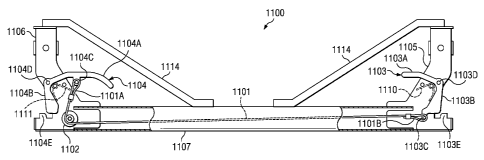
Figure 11 is a side view of a second embodiment 1100 of the invention. As seen
therein, a cable 1101 having a first end 1101A and a second end 1101B, couples
a first handle
1103 and linkage assembly in a first wedge head 1105 at one end of a
horizontal member
1107 to a second handle 1104 at the second wedge head 1106 via pulley 1102 at
a second end
of the horizontal member 1101. The first wedge head 1105 serves as a housing
around
portions of the first handle 1103 and second wedge head 1106 serves as a
housing around
portions of the second handle 1104.
More specifically, first handle 1103 is dimensioned as a substantially
horizontal
handle grip extension 1103A having a substantially vertical wedge 1103B
extending in a
substantially orthogonal direction due to an incurvature from the horizontal
handle grip
extension 1103A. Cable linkage assembly 1103C is located proximate the bottom
of the
vertical lock extension 1103B and serves as an anchor point from first handle
1103 to first
end 1101B of cable 1101.
Second handle 1104 is dimensioned as a substantially horizontal handle grip
extension 1104A having a substantially vertical wedge 1104B extending in a
substantially
orthogonal direction due to an incurvantre from the horizontal handle grip
extension 1104A.
Cable linkage assembly 1104C is located on the bottom of the horizontal handle
grip
extension 1104A between the end of the horizontal handle grip extension 1104A
and the
point of curvature from the horizontal handle grip extension 1104A to vertical
wedge 1104B
and serves as an anchor point from second handle 1104 to second end 1101A of
cable 1101.
First handle 1103 has an aperture 1103D located proximate the point of
curvature
between the horizontal handle grip extension 1103A and the vertical wedge
1103B, said
aperture 1103D to axially receive a pin, rivet, screw or other similar
structure through the
first handle 1103 so as to rotatably couple the first handle 1103 through the
walls of the first
wedge head 1105. The coupler, can include, but is not limited to a bolt and a
nut, rivet,
revolute, pin and associated washers, bushings and/or bearings, each coupler
being part of
linkage assembly.
Second handle 1104 has an aperture 1104D located proximate the point of
curvature
between the horizontal handle grip extension 1104A and the vertical wedge
1104B to axially
receive a pin, rivet, screw or other similar structure through the second
handle 1104 so as to
rotatably couple the second handle 1104 through the walls of the second wedge
head 1106.
The coupler, can include, but is not limited to a bolt and a nut, rivet,
revolute, pin and
9
CA 02824886 2013-07-16
WO 2012/102881 PCT/US2012/021346
associated washers, bushings and/or bearings, each coupler being part of
linkage assembly.
The tension of the cable 1101 operates to bias the wedge portions 1103B, 1104B
at
each end of the horizontal member simultaneously in either the locked or
unlocked position
depending on the position of their respective handles. The cable can be
threaded around
internal pins, wheels and axles and biased with springs. By actuating either
of handle 1103 or
1104, wedge portions 1103B, 1104B (respectively), can be simultaneously
retracted or
extended into the housing portions of wedge heads 1105, 1106, respectively.
Upward facing
teeth 1103E, 1104E, are integrated into the bottom of wedge heads 1105, 1106
to receive
rosette apertures when the wedge portions 1103B, 1104B are in the unlocked
positions, that
being when the first handle 1103 and second handle 1104 are in the upper
position. After the
rosettes are positioned within the teeth 1103E, 1104E (of which there may be a
plurality
integrated on the wedge heads 1105, 1006), force can be applied to either the
first handle
1103 or second handle 1104, which will cause both associated wedge portions
1103B, 1104B,
respectively, to move into the locked position. This simultaneous locking
effect is
accomplished by the action of the cable 1101 working in concert with the
applied force of
springs 1110, 1111.
First handle 1103 and second handle 1104, and associated wedge portions 1103B,
1104B are each springably biased into certain positions (extended (locked) or
retracted
(unlocked)) via springs 1110, 1111 which are coupled via pins, axles or
similar structure, to
wedge heads 1105, 1106.
Referring to Figure 11, which shows the unlocked position of the wedges, when
first
handle 1103 is in the up position, the second end 1101B of cable 1101 is in
the rightmost
position and higher compression is applied against spring 1110. At the same
time, second
handle 1104 is in the up position, first end 1101A of cable 1101 is in the
higher position and
higher compression is being applied against spring 1111.
Referring to Figure 12, which shows the locked position of the wedges, when
first
handle 1103 is in the down position, the second end 1101B of cable 1101 is in
the leftmost
position and less compression is applied against spring 1110. At the same
time, second
handle 1104 is in the down position, first end 1101A of cable 1101 is in the
lower position
and less compression is being applied against spring 1111. As can be seen, by
actuating one
handle to either lock or unlock its associated wedge portion, it cause the
other handle to move
and either lock or unlock its associated wedge portion simultaneously.
The embodiments further include being in combination with at least one rosette
attached, e.g., welded, to each vertical member. Each vertical member may have
a plurality
CA 02824886 2013-07-16
WO 2012/102881 PCT/1JS2012/021346
of evenly or unevenly spaced rosettes affixed, e.g., by weld, along a vertical
member. The
rosette has a pattern or grid of apertures designed to receive the mating
elements, such as
prongs at the end of a horizontal member. A wedge head may be located at the
end of the
horizontal member. The horizontal member is a hollow tube, preferably
cylindrical in shape,
having a first end and a second end. At the first end and the second end may
be fixedly
attached, a wedge head, as more fully described herein.
The invention further includes the method for coupling a horizontal member to
a
vertical member of a scaffold, comprising providing a horizontal member having
a wedge
head coupled to each end of the horizontal member, the wedge heads each having
therein a
wedge assembly partially within the wedge head, each wedge assembly pivotably
coupled to
its respective wedge head, each wedge assembly further comprising a handle
communicably
coupled via a wedge linkage assembly to a wedge, the wedge linkage assemblies
being
operatively coupled via a cam mechanism within the horizontal member; and
disengaging
either handle causing each wedge to simultaneously, partially retract into its
respective wedge
head. The method further includes the step of placing each wedge head on a
corresponding
rosette of a vertical member and engaging one of the handles so as to cause
each wedge to
lock the ends of the horizontal member simultaneously to the vertical members.
In an embodiment of the invention, the design of the wedge head at each end of
each
horizontal member keeps scaffold components square and ridged at all times
utilizing
predetermined angles via the grid design. The scaffold design of the invention
reduces
leading edge fall hazards associated with conventional scaffold systems. The
scaffold design
of the invention also reduces the need for hand tools during the installation
and dismantling
of horizontal members. Advantageously, the scaffold design of the invention
reduces the
amount of labor and time needed to install and dismantle a scaffold system.
The components of the invention can be fabricated from a variety of materials,
including galvanized or powder coated steel, iron or other resilient material.
The rosette
preferably has a seven inch (7") diameter, and the internal first and second
rods can comprise
two square, or cylindrical rods, made of e.g., steel or iron, each having a
wedge shaped
wedge portion added or integrated at an end, the opposite ends being coupled
to the
crank/cam assembly. Using the grid pattern of apertures on the rosette and
head having
prongs dimensioned to fit therein, various angles between the horizontal
members can be
obtained (e.g., 45, 90, 180 degrees) for the elevated working platform.
11
CA 02824886 2013-07-16
WO 2012/102881 PCT/US2012/021346
Advantageously, the invention allows the erector to engage and disengage both
wedge
portions of a single horizontal member from a single point reducing
installation time and
creating a safer work environment. This is because the only one of the handles
between the
first end and the second end of the horizontal member need be actuated to
engage and
disengage each wedge substantially simultaneously. In this manner, up to eight
(8) horizontal
members can be attached to a single vertical member by a single installer
without changing
his position.
The invention further comprises a grid of components that mesh together
creating
rigid angled connection among a plurality of horizontal members at a vertical
member. Both
of the wedges which are part of a wedge assembly, are locked into position at
the rosette on a
vertical member from a single position. The internal wedge portions are locked
into place by
an external handle eliminating the use of any hand tools. The external handle
can also be
locked into place creating a secondary locking device.
The embodiments shown and described above are only exemplary. Even though
numerous characteristics and advantages of embodiments of the invention have
been set forth
in the foregoing description together with details of the invention, the
disclosure is illustrative
only and changes may be made within the principles of the invention to the
full extent
indicated by the broad general meaning of the terms used herein. For example,
the concepts
described herein for coupling horizontal members to vertical members can be
used to couple
bracing members to vertical members or to horizontal members. Coupling
includes, but is
not limited to attaching, engaging, mounting, clamping, welding, bolting and
components
used for coupling include bolts and nuts, rivets, clevis, latches, clamps,
welds, screws, rivets
and the like. Further, a rosette having eight (8) radially arranged cut-outs
is described herein
for illustrative purposes and a rosette having more or less radially arranged
cut-outs is
considered to be within the scope of this invention. Also, the invention
describes a rosette
having a standard diameter of about seven (7) inches, however, any suitable
diameter can be
used. The use of a wedge head with a pair, or a wedge head with two pair, of
vertical prongs
is described herein for illustrative purposes and a wedge head having one or
more prongs is
considered within the scope of this invention. The rosette can include any
suitable cut-out
shape that is dimensioned to receive a corresponding prong or set of prongs of
a wedge head.
The vertical member can have any number of coaxially aligned rosettes attached
thereto, the
vertical spacing of such rosettes being any such distance as is suitable for
the intended use.
More generally, the invention is a scaffold system with a horizontal member, a
vertical
12
CA 02824886 2013-07-16
WO 2012/102881 PCT/US2012/021346
member with at least one rosette affixed in coaxial alignment to the vertical
member and a
wedge assembly within the horizontal member, portions of the wedge assembly
for locking
the horizontal member to the rosette. The vertical member has a plurality of
evenly spaced
rosettes affixed in coaxial alignment along the vertical member and at least
one rosette has a
pattern or grid of apertures designed to receive the end of the horizontal
member.
13