Note: Descriptions are shown in the official language in which they were submitted.
ULTRASONIC PROBE WITH ULTRASONIC TRANSDUCERS
ADDRESSABLE ON COMMON ELECTRICAL CHANNEL
BACKGROUND
The present disclosure relates to imaging systems and probes
employing ultrasonic imaging transducers. The present disclosure also relates
to methods of detecting changes in the angular orientation of movable
elements employed for directing radiation from imaging transducers during
minimally invasive imaging procedures. High resolution biomedical imaging
serves numerous purposes, including assessing tissue structures and
anatomy, planning and/or guiding interventions on localized regions of the
body, and assessing the result of interventions that alter the structure,
composition or other properties of a region,
High frequency ultrasound, in particular, has found significant use in
intracardiac and intravascular applications. For these applications,
ultrasound
transducers are incorporated into a catheter or other device that can be
inserted into a lumen or cavity within the body. Two important
implementations of high frequency ultrasound are intravascular ultrasound
1
CA 2824955 2018-05-14
CA 02824955 2013-07-17
WO 2012/103650
PCT/CA2012/050057
(IVUS) for imaging blood vessels, and intracardiac echocardiography (ICE) for
imaging cardiac chambers. Both ICE and IVUS are minimally invasive, and
involve placing one or more ultrasound transducers inside a blood vessel or
cardiac chamber to take high quality images of these structures.
Courtney et al. (US Patent Application Publication No.
US20090264768) describe an intravascular/intracardiac echocardiography
catheter capable of forward viewing via 3D ultrasound and/or optical imaging.
This is achieved using a movable member to image at various angles. This
device benefits from knowledge of the position and / or orientation of either
the imaging mechanism itself or of a deflecting element, such as a mirror.
In order to correlate the images obtained using an imaging transducer
with the orientation of the imaging probe, it is important to provide a
mechanism for determining the relative angular orientation of the movable
portion of an imaging system. This angular orientation determines an angle at
which imaging energy is transmitted and /or received from the imaging probe.
Courtney et al. disclose a number of angle detection mechanisms and
methods. One method involves relating the rotational speed to the imaging
angle, for example, using a look-up table. A series of electronic and
electromechanical techniques are also described, including capacitive,
resistive, electromagnetic, inductive, and strain gauge based techniques. Also
described are techniques that employ diffuse scattering from a reflector using
the primary imaging source. Also disclosed are optical and acoustic methods
and mechanism that utilize a detection sensor that is separate from the
primary imaging source to determine the imaging angle.
There are a number of limitations related to the techniques described
2
CA 02824955 2013-07-17
WO 2012/103650
PCT/CA2012/050057
above. For example, the use of a lookup table relating rotational speed to
imaging angle may be prone to significant inaccuracy. Different orientations
or
situations may influence the relationship between imaging angle and
rotational speeds. This may occur as a result of gravitational forces in
different
orientations, different temperature conditions, or stress on the catheter
among
others. Also, many techniques ¨ predominantly those using modalities other
than the imaging modality - may require the addition of significant complex
components and energy sources.
SUMMARY
Methods and apparatus are provided for electrically addressing
multiple ultrasonic transducers that are connected to a common electrical
channel and housed within an imaging probe. An imaging probe may
comprise an imaging ultrasonic transducer and a moveable element for
controlling the direction of an emitted imaging beam, and an angle sensing
ultrasonic transducer, where the angle sensing ultrasonic transducer is
configured for determining the direction of an ultrasonic imaging beam. The
angle-sensing transducer may be configured to direct an angle sensing
ultrasonic beam towards an acoustically reflective substrate and provide a
signal by detecting a reflected ultrasonic beam reflected from the
acoustically
reflective substrate, where the acoustically reflective substrate is
positioned
relative to the movable element such that motion of the movable element
produces a change in the signal.
Accordingly, in a first aspect, there is provided an imaging probe
comprising: a longitudinal body; a first ultrasonic transducer provided within
3
CA 02824955 2013-07-17
WO 2012/103650
PCT/CA2012/050057
the longitudinal body, wherein the first ultrasonic transducer is located
remote
from a proximal end of the longitudinal body, and wherein the first ultrasonic
transducer is configured to deliver an ultrasonic imaging beam to a region
outside of the longitudinal body and to receive reflected ultrasonic imaging
energy from the region; a second ultrasonic transducer housed within the
longitudinal body; and electrically conductive paths extending through the
longitudinal body and defining a common electrical channel; wherein the first
ultrasonic transducer and the second ultrasonic transducer are connected to
the common electrical channel, and wherein the common electrical channel is
electrically connectable to an image processing system.
In another aspect, there is provided an ultrasonic probe comprising: a
longitudinal body; a first ultrasonic transducer provided within the
longitudinal
body, wherein the first ultrasonic transducer is located remote from a
proximal
end of the longitudinal body, and wherein the first ultrasonic transducer is
configured to deliver an ultrasonic beam to a region outside of the
longitudinal
body; an additional ultrasonic transducer provided within the longitudinal
body
;an electrically conductive paths extending through the longitudinal body and
defining a common electrical channel; wherein the first ultrasonic transducer
and the additional ultrasonic transducer are connected to the common
electrical channel, and wherein the common electrical channel is electrically
connectable to an external processing system.
In another aspect, there is provided an ultrasonic angle detection
device for determining an angle of a pivotable member, wherein the pivotable
member is pivotally coupled to a solid support, the device comprising: an
electrically addressable ultrasonic transducer attached to the pivotable
4
CA 02824955 2013-07-17
WO 2012/103650
PCT/CA2012/050057
member, wherein the ultrasonic transducer is configured to emit ultrasonic
pulses in a direction that is dependent on an orientation of the pivotable
member; and an acoustically reflective substrate fixed relative to the solid
support and having a surface curvature selected to substantially retroreflect
.. the ultrasonic pulses back to the ultrasonic transducer over a defined
angular
range of the pivotable member, such that a distance between the ultrasonic
transducer and the acoustically reflective substrate, as determined along a
beam path of the ultrasonic pulses, varies over the angular range.
A further understanding of the functional and advantageous aspects of
.. the disclosure can be realized by reference to the following detailed
description and drawings.
BRIEF DESCRIPTION OF THE DRAWINGS
Embodiments of the disclosure will now be described, by way of
example only, with reference to the drawings, in which:
Figure 1 is a schematic of an imaging system including ultrasound and
optical components.
Figure 2 is a perspective drawing of a flexible imaging probe with an
adapter, conduit, and imaging assembly.
Figure 2a is a cross sectional view of the mid-section of the imaging
probe of Figure 2 taken along the dotted line.
Figure 2b is a magnified and expanded drawing of the distal region of
the imaging probe of Figure 2.
Figures 3a ¨ 3g describe embodiments of techniques for causing tilting
of a tiltable member.
5
CA 02824955 2013-07-17
WO 2012/103650
PCT/CA2012/050057
Figure 3a shows a longitudinal cutaway of a catheter in which the tilting
is caused by centripetal motion.
Figure 3b shows a cross-sectional cutaway of the catheter shown in
Figure 3a.
Figure 3c shows the catheter of Figure 3a and the resulting tilting
caused by rotating the scanning assembly at a faster rate than that of Figure
3a.
Figure 3d shows a cross-sectional cutaway of the catheter shown in
Figure 3c.
Figure 3e shows a longitudinal cutaway of a catheter in which the tilting
is controlled using one or more magnets.
Figure 3f shows a cross-sectional cutaway of the catheter in Figure 3e.
Figure 3g shows the catheter of Figure 3e and the resulting deflection
caused by magnetism.
Figure 3h shows a cross-sectional cutaway of the catheter in Figure 3g.
Figure 3i shows a potential scanning pattern for generating 3D images
with imaging angle information.
Figure 3j illustrates a control system in which the angle sensing
transducer is employed to provide feedback for controlling a direction of the
emitted imaging beam.
Figure 3k shows an implementation of a system using a torsional
spring as a restoring mechanism.
Figure 4 demonstrates the use of a high frequency ultrasound
transducer to estimate the tilt angle of a tiltable ultrasound transducer
using a
time of flight method. Figures 4a and 4b show the measurement of the tilt of
6
the bitable component at two different angular orientations. Figures 4c and 4d
plot the time dependence of the transmitted and received ultrasonic pulses for
the angular orientations shown in Figures 4a and 4b, respectively. Figure 4e
plots the dependence of the time delay of the ultrasonic beam on the tilt
angle. Figures 4f and 4g show example embodiments in which ultrasound
transducers have similar and larger dimensions, respectively, in the range
direction compared to the elevation directions
Figures 5a and 5b show connection schemes of ultrasound
transducers to produce acoustic energy through multiple ultrasound
transducers via a single electrical connection. Figure 5a shows a case where
an imaging transducer and an angle detection transducer are directly bonded
together. Figure 5b shows a case where an imaging transducer and an angle
detection transducer are physically separated, but connected electrically.
Figures 5c-5e illustrate embodiments in which two imaging ultrasonic
transducers are housed within a sheath and connected to a common electrical
channel for simultaneous imaging in antiparallel (Figure 5c) and orthogonal
(Figures 5d-5e), and parallel (Figure 5f). Figure 5g shows a three-frequency
imaging arrangement; and Figure 5h shows an arrangement with a two-
frequency assembly combined with an optical imaging modality. Figure 5i
shows an arrangement with focused ultrasound transducers.
Figure 6 shows a separation between the active bandwidths of two
ultrasound transducers connected to a common channel.
Figure 7 shows the use of tuning elements for the two ultrasound
transducers using separate RLC circuits for each of the transducers.
Figures 8a-8e demonstrates the use of a high frequency ultrasound
7
CA 2824955 2018-05-14
transducer to estimate the deflection of a tiltable optical and/or acoustic
mirror. Figures 8a and 8b show the measurement of the tilt angle of the
7A
CA 2824955 2018-05-14
CA 02824955 2013-07-17
WO 2012/103650
PCT/CA2012/050057
tiltable mirror at two different angular orientations. Figures 8c and 8d plot
the
time dependence of the transmitted and received ultrasonic pulses for the
angular orientations shown in Figures 8a and 8b, respectively. Figure 8e
plots the dependence of the time delay of the ultrasonic beam on the
deflection angle.
Figures 9a-9e demonstrate the use of a high frequency ultrasound
transducer to estimate the angular orientation of an ultrasound transducer
mounted on a deformable member. Figures 9a and 9b show the
measurement of tilt of the mirror at two different angular orientations.
Figures
9c and 9d plot the time dependence of the transmitted and received ultrasonic
pulses for the angular orientations shown in Figures 9a and 9b, respectively.
Figure 9e plots the dependence of the time delay of the angle detecting
ultrasonic beam on the tilt angle.
Figures 10a-10e demonstrate the use of a high frequency ultrasound
transducer to estimate the deflection angle of a tiltable component using a
method that assesses the intensity of the received signal. Figures 10a and
10b show the measurement of the tilt of a tiltable component at two different
angular orientations. Figures 10c and 10d plot the time dependence of the
transmitted and received ultrasonic pulses for the angular orientations shown
in Figures 10a and 10b, respectively. Figure 10e plots the dependence of the
peak voltage relating to the received ultrasonic beam on the deflection angle.
Figures lla and llb show (a) the use of a surface comprising a
specular reflector in comparison with (b) a diffuse reflector. Figures 11c and
11d plot the time dependence of the transmitted and received ultrasonic
pulses for the angular orientations shown in Figures lla and 11b,
8
CA 02824955 2013-07-17
WO 2012/103650
PCT/CA2012/050057
respectively.
Figures 12a-d demonstrate the use of two high frequency ultrasound
transducers to estimate the deflection angle of a tiltable component using a
time of flight method, shown in (a) and (b) at two different angular
orientations. Figures 12c and 12d plot the time dependence of the transmitted
and received ultrasonic pulses for the angular orientations shown in Figures
12a and 12b, respectively.
Figures 13a-e show a disc with curved features to increase the range
of angles that can be detected using a time of flight method, shown in (a) and
(b) at two different angular orientations. Figures 13c and 13d plot the time
dependence of the transmitted and received ultrasonic pulses for the angular
orientations shown in Figures 13a and 13b, respectively. Figure 13e plots the
dependence of the time delay of the ultrasonic beam on the deflection angle.
Figures 14a-d show the use of an ultrasound transducer that diffusely
emits and detects ultrasound energy to increase the range of angles that can
be detected using a time of flight method, shown in (a) and (b) at two
different
angular orientations. Figures 14c and 14d plot the time dependence of the
transmitted and received ultrasonic pulses for the angular orientations shown
in Figures 14a and 14b, respectively.
Figures 15a-d show the use of a curved surface to increase the range
of angles that can be detected with improved precision using a time of flight
method with an angle detection transducer attached to a tiltable component,
shown in (a) and (b) at two different angular orientations. Figures 15c and
15d
plot the time dependence of the transmitted and received ultrasonic pulses for
the angular orientations shown in Figures 15a and 15b, respectively. Figure
9
CA 02824955 2013-07-17
WO 2012/103650
PCT/CA2012/050057
15e illustrates the relationship between the curvature of the surface and the
orientation of the transducer, such that the surface is locally approximately
normal to the incident acoustic beam to ensure strong received signals.
Figures 16a-d show the use of a high frequency ultrasound transducer
to estimate the tilt angle of a tiltable ultrasound transducer mechanically
coupled to an otherwise acoustically passive component with the angle
detection transducer mounted on the otherwise acoustically passive
component, shown in Figures16a and 16b at two different angular
orientations. Figures 16c and 16d plot the time dependence of the transmitted
and received ultrasonic pulses for the angular orientations shown in Figures
16a and 16b, respectively. Figure 16e shows some geometric relationships
that can be used to calculate the tilt angle from the knowledge of the
distance
between angle detection transducer and a constant distance between a point
on each of two tiltable components.
Figures 17a-d show the use of a high frequency ultrasound transducer
to estimate the deflection angle of a tiltable ultrasound transducer
mechanically coupled to an acoustically passive component with an angle
detection transducer integrated onto an imaging transducer. Figures 17c and
17d plot the time dependence of the transmitted and received ultrasonic
pulses for the angular orientations shown in Figures 17a and 17b,
respectively.
Figures 18a-b show the use of the curved surface shown in Figure 15
with a mechanically coupled acoustically passive component similar to that
shown in Figures 16 and 17. Figure 18a shows a view with the same
perspective shown in Figure 17. Figure 18b shows a view cut through the
CA 02824955 2013-07-17
WO 2012/103650
PCT/CA2012/050057
hatched line from Figure 18a.
Figures 18c-18i show an embodiment in which the position of the
mechanical coupler is detected using the angle detection transducer to
estimate the angle of deflection. Figures 18c and 18e show the tiltable
member at two different positions. Figures 18d and 18f show views cut
through the hatched line from Figures 18c and 18e respectively. Figures 18g
and 18h show timing diagrams from the scenarios described in Figures 18d
and 18f respectively. Figure 18i shows a relationship between the received
time delay and the tilt angle.
Figures 19a-g show a sample pulse sequence and corresponding
received signal from both the imaging transducer and the deflection angle
transducer on a single channel using multiple methods. Figure 19a shows the
measurement of two features, and Figure 19b shows how the signals from the
two features and the signal from the angle detection transducer can be
extracted based on an interleaved pulsing scheme.
Figure 19c shows an example using either or both of: prior knowledge
of distance ranges and using spectral methods. Figure 19d shows how the
signals from the two features and the signal from the angle detection
transducer can be extracted based on whether or not they are beyond the
maximum distance range used in the angle detection scheme. Figures 19e
shows an example of the use of spectral methods to separate angle detection
information from imaging information.
Figure 19f shows a transmit pulse sequence where multiple imaging
pulses are transmitted between single angle detection pulses. Figure 19g
shows a transmit pulse sequence where there is a long time delay between
11
CA 02824955 2013-07-17
WO 2012/103650
PCT/CA2012/050057
the imaging pulse and the subsequent angle detection pulse, and a short time
delay between the angle detection pulse and the subsequent imaging pulse.
Figures 20a-b show different estimation methods for determining a
distance as detected by an angle detection transducer. Figure 20a shows an
example of the detection of the distance based on the use of radio-frequency
(RF) peak detection methods and envelope detection methods, while Figure
20b example illustrates the detection of the distance based on the use of
cross correlation methods.
Figure 21 shows experimental data obtained from an angle detection
experiment conducted with the embodiment described in Figure 18a and 18b.
DETAILED DESCRIPTION
Various embodiments and aspects of the disclosure will be described
with reference to details discussed below. The following description and
drawings are illustrative of the disclosure and are not to be construed as
limiting the disclosure. Numerous specific details are described to provide a
thorough understanding of various embodiments of the present disclosure.
However, in certain instances, well-known or conventional details are not
described in order to provide a concise discussion of embodiments of the
present disclosure. It should be understood that the order of the steps of the
methods disclosed herein is immaterial so long as the methods remain
operable. Moreover, two or more steps may be conducted simultaneously or
in a different order than recited herein unless otherwise specified.
As used herein, the terms, "comprises" and "comprising" are to be
construed as being inclusive and open ended, and not exclusive. Specifically,
12
CA 02824955 2013-07-17
WO 2012/103650
PCT/CA2012/050057
when used in the specification and claims, the terms, "comprises" and
"comprising" and variations thereof mean the specified features, steps or
components are included. These terms are not to be interpreted to exclude
the presence of other features, steps or components.
As used herein, the term "example" means "serving as an example,
instance, or illustration," and should not be construed as preferred or
advantageous over other configurations disclosed herein.
As used herein, the terms "about" and "approximately", when used in
conjunction with ranges of dimensions of particles, compositions of mixtures
or other physical properties or characteristics, are meant to cover slight
variations that may exist in the upper and lower limits of the ranges of
dimensions so as to not exclude embodiments where on average most of the
dimensions are satisfied but where statistically dimensions may exist outside
this region. It is not the intention to exclude embodiments such as these from
the present disclosure.
For example, in embodiments of the present disclosure, dimensions of
components of the imaging probe are given but it will be understood that
these are not meant to be limiting.
As used herein, the term "high resolution imaging" generally refers to
optical imaging methods and high frequency ultrasound, the latter of which
typically involving frequencies of greater than 3 MHz, and more typically
involving frequencies in the range of 5 to 100 MHz.
As used herein, the terms "imaging radiation" and "imaging energy"
refer to electromagnetic or acoustic radiation, or both. Specifically,
electromagnetic radiation may span the ultraviolet, visible, and or infrared
13
CA 02824955 2013-07-17
WO 2012/103650
PCT/CA2012/050057
spectrum of wavelengths.
As used herein, the term "deflect" refers to a change in at least an
angular orientation of an object relative to. In one example, a deflection may
be a change in the tilt of a tiltable component or a change in an angular
orientation of a movable member. As used herein, the term "tilt" refers to the
angular orientation of an object. A change in angular orientation, as defined
by a change in a tilt angle, may be relative to another portion of an object
if
the object is deformable, or relative to another object within an assembly of
objects. For example, a component mounted on a pivot mechanism may tilt
by pivoting around an axis of the pivot mechanism. Alternatively, a
component mounted on a deformable component or integrated as part of a
deformable component may experience a tilt as a result of deformation of the
deformable component.
As used herein, the term "move" refers to a change in either an angular
orientation of an object, a position of an object or both the angular
orientation
and position of an object. For example, the movement of an object may occur
as a result of a tilting an object or pivoting of an object around an axis.
Movement may also occur as a result of a deformation an object or a
deformable portion of an object. Movement may also occur as a result of
translation of an object. The movement of an object may be in absolute
terms, relative to another portion of an object if the object is deformable,
or
relative to another object within an assembly of objects.
As used herein, the term "electrical channel" refers electrically
conductive paths that are suitable for delivering electrical energy to, or
detecting electrical signals from, an electrical element, such as an
ultrasonic
14
CA 02824955 2013-07-17
WO 2012/103650
PCT/CA2012/050057
transducer. An example of an electrical channel includes two conductors,
such as wires, that are contacted with an electrical element such that when a
voltage difference is applied between the conductors, a corresponding voltage
is applied across the electrical element.
Embodiments of the disclosure provide apparatus and methods for the
non-contact detection of a change in orientation or position of a movable
member. An ultrasonic transducer is employed to generate an incident
ultrasonic beam and to detect a reflected ultrasonic beam, where the
deflection of a deflectable member produces a change in one or more of: a)
the intensity, b) the time delay, or c) the spectral content of the reflected
beam. The proceeding disclosure describes and illustrates, through examples,
the application of various embodiments to minimally invasive imaging systems
and methods. However, it is to be understood that these applications are
merely non-limiting examples, and the embodiments disclosed here are
applicable and adaptable to a wide range of uses and applications.
Before describing example embodiments and their application to
minimally invasive imaging systems, a brief review of minimally invasive
imaging systems is provided with reference to Figures 1 to 3, by way of
example. Referring first to Figure 1, an imaging system is shown at 10
comprising imaging probe 44, which connects via patient interface module 36
to image processing and display system 49. Image processing and display
system 49 includes hardware to support one or more imaging modalities, such
as ultrasound, optical coherence tomography, angioscopy, infrared imaging,
near infrared imaging, Raman spectroscopy-based imaging, or fluorescence
imaging. Specific embodiments of ultrasonic imaging probes and combined
ultrasonic and optical imaging probes are disclosed by Courtney et al. in US
Patent Publication No. 20080177183, titled "Imaging Probe with Combined
Ultrasounds and Optical Means of Imaging" and filed on January 22, 2008,
US Patent Publication No. 20080177138, titled "Scanning Mechanisms for
Imaging Probe" and filed on January 22, 2008 and US Patent Publication No.
20090264768, titled "Scanning Mechanisms for Imaging Probe" and filed on
March 27, 2009.
Controller and processing unit 34 is employed to facilitate the
coordinated activity of the many functional units of the system, and may
contain some or all of the components shown in the Figure and listed herein.
An operator interacts with system 50 via display and/or user interface 38.
System 10 may further include electrode sensors 40 to acquire
electrocardiogram signals from the body of the patient being imaged. The
electrocardiogram signals may be used to time the acquisition of imaging data
in situations where cardiac motion may have an impact on image quality. The
electrocardiogram may also serve as a trigger for when to begin an
acquisition sequence, such as when to begin changing the speed of rotation
of a motor in order to cause a desired scan pattern to take effect. For
example, electrocardiogram triggered initiation of an imaging sequence may
enable images to be acquired during a particular phase of the cardiac cycle,
such as systole or diastole.
Optical subsystem 30, if included in a particular implementation of an
imaging system, may include any or all of the following components:
interferometer components, one or more optical reference arms, optical
16
CA 2824955 2018-05-14
CA 02824955 2013-07-17
WO 2012/103650
PCT/CA2012/050057
multiplexors, optical demultiplexers, light sources, photodetectors,
spectrometers, polarization filters, polarization controllers, timing
circuitry,
analog to digital converters, parallel processing arrays and other components
known to facilitate any of the optical imaging techniques. Ultrasound
.. subsystem 32 may include any or all of the following components: pulse
generators, electronic filters, analog to digital converters, parallel
processing
arrays, envelope detectors, amplifiers including time gain compensation
amplifiers and other components known to facilitate acoustic imaging
techniques.
Controller and processing units 34, if included in a particular
implementation of the imaging system, serve multiple purposes. Those skilled
in the art will appreciate that specific components required depend on the
needs of a particular type of imaging system. For example, controller and
processing units may include any combination of a motor drive controller, data
storage components (such as memory, hard drives, removable storage
devices, readers and recorders for media such as CDs, DVDs, and BlurayTm
discs), position sensing circuitry and/or software, angle detection circuitry
and/or software, timing circuitry and/or software, cardiac gating
functionality,
volumetric imaging processors, scan converters and others. As noted above,
display and user interface 38 is also optionally provided for either real time
display or display of data at a time later than the time at which imaging data
is
acquired.
It is to be understood that patient interface module 36 and controller
and processing units 34 are but one example illustration of the selection and
organization of hardware subsystems, and that many other implementations
17
CA 02824955 2013-07-17
WO 2012/103650
PCT/CA2012/050057
are possible. For example, patient interface module 36 may be housed with
controller and processing units 34 within processing and display system 49.
Example imaging probe 44 includes an imaging assembly 50, optional
imaging conduit 46 along a substantial portion of its length, and connector 48
at its proximal end 47. Imaging assembly 50 is located near distal end 41 of
imaging probe 44. Imaging assembly 50 generally refers to the components
of the imaging probe 44 from which the signals (either acoustic, optical or
both) are collected for the purposes of imaging a region that is proximate to
imaging assembly 50. Imaging assembly 50 may house transducers for
transmitting and/or receiving imaging radiation. The emitter and receiver may
be a single component, as is often the case with a piezoelectric transducer.
In the case of optical imaging, imaging assembly 50 typically contains
the distal tip of a fiber optic, as well as a combination of optical
components
such as a lens (for instance, a ball lens or a GRIN lens). A mirror and/or
prism
may be included for use in beam delivery and/or collection. Optionally, there
may be an optical detector, such as a CCD array, or an optical light source,
such as one or more LEDs, incorporated directly in the imaging assembly that
may obviate the need for one or more fiber optics in an optical imaging probe.
Imaging probe 44 may contain ports at one or more points along its
.. length to facilitate flushing. Moreover, imaging assembly 50, connector 48
and/or imaging conduit 46 may be filled and / or surrounded with a fluid such
as saline, and may be flushed. In applications involving optical imaging,
imaging probe 44 may be filled with a gas. The gas may include carbon
dioxide or another readily dissolved gas with minimal biotoxicity.
Alternatively,
in the case of a multimodal optical/acoustic imaging system, imaging
18
CA 02824955 2013-07-17
WO 2012/103650
PCT/CA2012/050057
assembly 50 may be compartmentalized to include at least one gas-filled
compartment or lumen for optical imaging and at least one fluid filled
compartment or chamber for acoustic imaging.
Imaging conduit 46 includes at least one conductive wire (optionally
two or more) that connect an emitter and/or receiver via connection to an
adapter, herein referred to as patient interface module 36. Imaging conduit 46
may include a fiber optic, for example, wrapped by two layers of electrical
wire
that are electrically insulated from one another. Imaging conduit 46 may
further be reinforced by other structural features, such as helically wrapped
wires or other designs used to construct imaging torque cables for rotating
scan mechanisms. Alternatively, imaging conduit 46 may contain electrical
conductors, and a rotational mechanism may be located remote from the
proximal end for imparting rotary motion to the imaging assembly. One
example mechanism includes a micro-motor and a slip ring in close proximity
to the imaging assembly.
The imaging probe 44 may optionally include memory, such as an
EEPROM for storing information including calibration information, serial
information, probe design information, desired filter information, and any
other
probe specific information. This memory may reside in connector 48.
Patient interface module 36 facilitates transmission of signals within
any fibers and/or wires to the appropriate image processing units. It may
contain a motor drive unit for imparting rotational motion to the components
of
the imaging mechanism.
Additional sensors may be incorporated as part of patient interface
module 36, such as position sensing circuitry, for example, to sense the angle
19
CA 02824955 2013-07-17
WO 2012/103650
PCT/CA2012/050057
of rotation of a rotary component within the imaging probe 44 and/or for
detecting the angle of deflection of a member at the distal end 41 of the
imaging probe 44. Additionally, patient interface module 36 may include
amplifiers to improve the transmission of electrical signals or power between
the imaging probe 44 and the rest of the system.
In many applications, it can be important to optimize the geometry of a
minimally invasive probe so that it is as small as reasonably possible to
achieve its desired purpose. Current IVUS and ICE probes are approximately
0.9 to 4 mm in diameter and the smaller sizes of probes can be delivered
more distally within the vascular tree of the coronary anatomy as the vessel
caliber tapers down or as diseased vessels are stenosed. Furthermore, within
the cardiac anatomy, smaller probes (such as those with a diameter less than
about 3.4 mm) can be readily advanced across the atrial septum into the left
atrium of the heart. Thus, smaller sizes generally allow for interrogation of
a
larger portion of the coronary or cardiac anatomy. It is therefore desirable
for
a probe and its components to be contained within a minimal outer diameter
to enable imaging, such as using imaging performed with the scanning
mechanisms described by Courtney et al. (US Patent Application Publication
No. 20080177138).
Figure 2 is a perspective drawing of a flexible catheter containing fiber
optic 66 and co-axial electrical cable 68. The proximal connector contains
fiber optic connection joint 60 that can be received by patient interface
module 36 to optically couple imaging fiber optic 66 to image processing and
display system 49. Electrical connectors 62 allow one or more electrical
conduits to be connected to the ultrasound circuitry and/or controller and
CA 02824955 2013-07-17
WO 2012/103650
PCT/CA2012/050057
processing units. In applications in which the imaging conduit rotates around
its longitudinal axis, there may be a need to couple the rotating components
of
the imaging fiber optic with a relatively stationary fiber optic that connects
to
image processing and display system 49. This coupling can be achieved
with the use of a fiber optic rotary joint incorporated either as part of the
proximal connector of imaging probe 48 or as part of patient interface module
36. Similarly, there may need to be a mechanism for coupling the rotating
components of the electrical system with relatively stationary electrical
components that connect to image processing and display system 49. This
can be achieved through the use of one or more electrical slip rings or slip
ring channels.
Figure 2a shows a cross sectional view of the middle section of the
catheter shown in Figure 2 taken along the dotted vertical line. The cross
section shows the optional fiber optic 66, optional guidewire 52, imaging
conduit lumen 47, external sheath 43, which is a hollow, flexible elongate
shaft made of physiologically compatible material and having a diameter
suitable to permit insertion of the hollow elongate shaft into bodily lumens
and
cavities, and co-axial wiring 68. The expanded detailed view of the end of the
imaging probe 44 in Figure 2b shows the imaging assembly 50 which
optionally includes a tiltable member 51, distal end of the optional guidewire
52 extended beyond the end of the external sheath 43 and a flush port 53
near the end of the sheath 43. In Figure 2, the proximal end of the imaging
probe 44 includes an optional guidewire port 56 into which the guidewire 52 is
inserted and the connector assembly 48 includes a flush port 58 and electrical
contacts 62 along with the connector body. An optional guidewire port 54 is
21
CA 02824955 2013-07-17
WO 2012/103650
PCT/CA2012/050057
seen in Figure 2b.
Figures 3a-d show an example catheter that employs a tiltable member
for scanning an imaging beam. Figure 3a shows a perspective cutaway
drawing of the distal region of an imaging probe 44 that relies on centripetal
force to generate the change in tilt angle of the tiltable member 51. Imaging
probe 44, which includes a sheath 43 for isolation from bodily fluids and
cavities, includes tiltable member 51 housed within imaging assembly 50.
Tiltable member 51 is mounted on pins 102, about which tiltable
member 51 is free to pivot. As imaging conduit 46 and assembly 50 (not
shown) are rotated about longitudinal axis 59 at a slow rate (indicated by
arcing hatched arrow 61), the angle a subtended between longitudinal axis 59
and tiltable member 51 is relatively small. A cutaway perspective cross-
sectional view of Figure 3a is shown in Figure 3b. Figure 3c shows a similar
drawing of the distal region of imaging probe 44 as shown in Figure 3a,
except with imaging conduit 46 being rotated at a faster rate (indicated by
arcing hatched arrow 63) than in Figure 3a. Centripetal force causes tiltable
member 51 to tilt such that there is an increase in the angle a subtended
between the longitudinal axis of the catheter and the tiltable member 51.
Figure 3d is a cutaway perspective cross-sectional view from Figure 3c.
Figure 3e shows a perspective cutaway drawing of the distal region of
a related imaging probe 44 that relies on the use of dynamically controlled
magnetic fields to change the deflection angle of tiltable member 51. Imaging
probe 44, which may include a sheath 43 for some degree of isolation from
bodily fluids and cavities, includes tiltable member 51 comprising part of the
imaging assembly 50. Tiltable member 51 is mounted on pins 102, about
22
CA 02824955 2013-07-17
WO 2012/103650
PCT/CA2012/050057
which the tiltable member 51 is free to pivot. Mounted on the tiltable member
51 is a magnetically influenced element 109 that can be either attracted or
repulsed by a magnetic field. For example, it may be a ferromagnetic
component, or a permanent magnetic component. Element 109 may
integrally be part of tiltable member 51, such as if all or a portion of
element
109 is made of either a ferromagnetic or magnetic substrate. An
electromagnetic component 107 is also placed at a position separate from the
tiltable member 51. The electromagnetic component can be controlled to
produce attractive or repulsive forces relative to magnetically influenced
.. component 109. In so doing, the angle a subtended between the longitudinal
axis 59 of the catheter and the tiltable member can be adjusted as desired.
Furthermore, similar imaging probes may be conceived that involve
interchanging the position of the electromagnetic component 107 and
magnetically influenced component 109, or using two electromagnets instead
.. of an electromagnet and a magnetically influenced component. A cutaway
perspective cross-sectional view of Figure 3e is shown in Figure 3f.
Figure 3g shows a similar drawing of the distal region of imaging probe
44 as shown in Figure 3e, except with a repulsive sequence applied to
electromagnet 107 such that the angle a subtended by tiltable member 51 is
.. increased. Figure 3h is a cutaway perspective cross-sectional view from
Figure 3g.
Tiltable member 51 may be an ultrasonic transducer, such as an
ultrasound transducer used for producing B-scan ultrasound images. Another
embodiment includes an ultrasound transducer mounted on a tiltable member.
Figure 3i shows an example of a potential scanning pattern for
23
CA 02824955 2013-07-17
WO 2012/103650
PCT/CA2012/050057
generating ultrasound images. In this case, the tiltable member is an
ultrasound imaging transducer 101. As imaging conduit 46 and assembly 50
are rotated at a constant rate, an image is generated along a surface that
approximates a cone. As the rate of rotation is changed, centripetal force
causes the angle subtended between the longitudinal axis of the catheter and
ultrasound imaging transducer 101 to change resulting in a series of
concentric imaging cones 118 for different rotational speeds. The angle
subtended between the longitudinal axis of the catheter and an axis normal to
ultrasonic imaging transducer 101 will be referred to as the "imaging angle".
In
.. this case, the transducer begins with a relatively small imaging angle 01
implying a fast rate of rotational speed. As the rotational speed is reduced,
the
imaging angle is increased to 02.
In order to cause the imaging angle to return to a stable position in the
absence of rotation, a restoring mechanism can be used as shown in Figure
.. 3k. Here, the primary movable member 101 is connected to a secondary
movable member 114 using a mechanical coupler 176, allowing the two
members 101 and 114 to move synchronously. All components are housed
within a shell 178. One or more springs 182 are connected between the
movable member 101 and the shell 178. The springs may be torsion springs,
linear springs, or a cantilever spring. The movable members 101 and 114 are
pivotally supported by around pins 111 and 113 respectively. This spring 182
provides a force to restore the member 101 to the side viewing position in the
absence of adequate rotational force to overcome the restoring force provided
by spring 182. In addition to adding a mechanical restoring force, the
torsional
springs may also be formed, at least in part, from an electrically conductive
24
CA 02824955 2013-07-17
WO 2012/103650
PCT/CA2012/050057
material, such as stainless steel, beryllium copper, copper, silver, titanium,
gold, platinum, palladium, rhenium, tungsten, nickel, cobalt, alloys that
include
one or more of these metals and many other metals and their alloys can be
used to provide electrical connections. Here, spring 182 is in electrical
communication with conductor 300. Conductor 301 makes a similar
connection to the opposite side of movable member 101 (not shown).
Alternatively a spring that provides both a restoring force and an
electrical connection may be made of more than one material, where one
material provides conductive properties and another material provides
mechanical properties for the restoring force. For example, a torsion spring
may be formed of a nitinol core with a gold outer layer, applied by
sputtering,
plating, evaporation, electroforming, electroplating, electron beam techniques
or other methods known in the art. Alternatively, one or more of the materials
may be a material other than a metal, such as a polymer.
The conducting elements of the spring have cross sectional
dimensions on a micron scale (for example, less than about 100 microns x
100 microns) using photolithography and related techniques. Gold hardened
with cobalt and nickel cobalt provide further examples of suitable materials
for
a conductive spring with desired mechanical properties. A portion of the
.. surface of the spring may be covered by an insulating material, such as
parylene, Teflon, polyimide and many others. Alternatively, the insulating may
occur by processing the outer surface of the spring, such as by allowing an
oxide to form on the outer surface of a metal or alloy.
Example embodiments described below provide ultrasonic apparatuses
and methods for combining multiple ultrasound transducers on a single
CA 02824955 2013-07-17
WO 2012/103650
PCT/CA2012/050057
electrical channel. One application that will be described in detail relates
to
the fact that in order to accurately reconstruct a 3D image of the imaging
field,
the imaging angle must be determined for a given ultrasound image
acquisition event, vector, or pixel. As noted above, while the proceeding
embodiments relate to applications involving minimally invasive imaging,
where angular detection is performed using an apparatus mounted within an
imaging assembly within an imaging probe, it is to be understood that these
applications are merely non-limiting examples that are provided for teaching
purposes and are not intended to limit the scope of the disclosed
embodiments.
Referring now to Figure 4, an ultrasonic angle detection apparatus is
shown for detecting a change in angle of a tiltable member using a time of
flight detection method. Angle detection transducer 100 is placed at a fixed
location relative to an initial position of tiltable member 101, which
includes
material that is at least partially acoustically reflective relative to the
acoustic
transmission medium. Angle detection transducer 100 transmits ultrasonic
beam 110 towards the tiltable member 101. As the beam reaches the tiltable
member 101, a portion of the beam is reflected back towards the angle
detection transducer 100. The acoustically reflective substrate may be
configured to reflect or scatter components of the incident ultrasonic beam in
a diffuse manner, as will be described in further detail below.
Tiltable member 101 may itself be acoustically reflective, or may have
attached to one or more of its surfaces, such as its back surface, an
acoustically reflective substrate. As noted above, acoustic reflections may be
diffuse to support the detection of a reflected ultrasonic beam over a broad
26
CA 02824955 2013-07-17
WO 2012/103650
PCT/CA2012/050057
range of tilt angles (or imaging angles), and the reflected ultrasonic beam
may
be generated by surface reflection, volume reflection, or a combination
thereof. In an example embodiment, tiltable member 101 includes an imaging
transducer that transmits an acoustic beam 120 in a direction away from the
angle detection transducer 100. It is not necessary that the angle detection
mechanism only uses the back surface of the tiltable member. It may be
oriented and /or positioned to use any side or surface of the tiltable member
as best suited for any particular embodiment.
Figures 4a and 4b show two different angular positions of tiltable
member 101, which is rotatable about pivot axis 102. In one example
embodiment, the pivot axis is implemented using or more pins or a hinge
aligned along the pivot axis around which the tiltable member pivots. In
Figure 4a, the separation between tiltable member 101 and angle detection
transducer 100 is greater than in Figure 4b. This separation distance results
in
the angle detection beam 110 having a shorter time of flight in Figure 4b than
Figure 4a.
The tilt angle can be calculated with the time of flight and prior
knowledge of the geometric configuration of the transducer and the tiltable
component, including their relative locations in space and ranges of motion,
and the speed of sound in the acoustic path. The acoustic beam for the angle
detection transducer may travel through a medium such as water or saline,
wherein the speed of sound is approximately 1450 to 1600 m/s.
For example, if the angle is to be determined based on differences in
time of flight, a baseline signal may be captured at a known angular position
and known estimated time of flight during an initialization phase. This
baseline
27
CA 02824955 2013-07-17
WO 2012/103650
PCT/CA2012/050057
signal may be used as a comparator against signals received at different
positions to estimate tilt angle using the techniques described above.
Alternatively, the tilt angle can be determined empirically based on
calibration measurements made with known angular deflections. Calibration
measurements can be employed to produce a calibration curve, such as the
curve shown in Figure 4e. Such calibration data may be stored in an
EEPROM provided within the imaging probe, as described above.
Figures 4c and 4d are timing diagrams that represent the signal
detected for each angle scenario in Figures 4a and 4b, respectively. In these
examples, a pulse 500 is transmitted from transducer 100 at time (t) =0 and a
received pulse is detected at a later time with a reduced magnitude. The
received pulse 502 corresponding to the signal reflected from tiltable member
101, as oriented in Figure 4a, has a greater time delay than the received
pulse 504 corresponding to the signal reflected from tiltable member 101 in
Figure 4b. Furthermore, as acoustic waves propagate through a medium, they
are partially attenuated. This attenuation is frequency dependent with energy
components in the higher frequencies attenuated more than lower frequency
energy components. As a result of this, not only is the delay between received
pulses changed, so too is the spectral content of the received pulse 504. In
this embodiment, a change in spectral content can also be related to the tilt
angle.
The tilt angle determined using the above method may be employed for
feedback in a control system, as shown in Figure 3j. A desired angle 194 and
the measured angle 192 (determined using the aforementioned method) are
provided as inputs to controller 196, and the output of controller 196 is
28
CA 02824955 2013-07-17
WO 2012/103650
PCT/CA2012/050057
provided to angle control mechanism 190. A variety of control methods and
algorithms known in the art may be employed, including, but not limited to,
PID and fuzzy logic controllers.
In another example embodiment, the tiltable member is employed to
direct a beam of ultrasonic radiation from an imaging ultrasonic transducer
housed within an imaging probe, where the ultrasonic imaging transducer and
the angle sensing transducer are electrically connected to a common channel
for excitation and detection. The ultrasonic imaging transducer may form
tiltable member 101, or alternatively may be mounted to tiltable member 101,
or may be fixed relative to tiltable member 101 such that the imaging beam is
reflected, scattered, and/or refracted by tiltable member 101 (as shown in
embodiments described below).
By connecting both transducers to a common electrical channel, a
simple, reliable, cost-effective, and space efficient system is realized.
Furthermore, the ability to use a common electrical channel may minimize the
number of electrical connections that need to be made. For example, if the
electrical connections to an ultrasound imaging transducer mounted on or
incorporated as tiltable member 101 are via wires or conductive springs from
the housing of imaging assembly 50 to tiltable member, the wires or springs
will mechanically influence the ease with which tiltable member can tilt. It
may
be desirable to minimize the number of wires or springs between tiltable
member 101 and the rest of the imaging assembly 50.
Using a common electrical channel for both an imaging transducer and
an angle detection transducer reduces the number of electrical conductors to
the tiltable member and may thus provide more flexibility in the design and
/or
29
CA 02824955 2013-07-17
WO 2012/103650
PCT/CA2012/050057
performance of the imaging probe. Similarly, using a common electrical
channel may reduce the number of channels that need to be accommodated
by the patient interface module 36 (the patient interface module contains
components, such as slip rings, that couple electrical signals between the
.. rotating parts of the imaging probe and the non-rotating parts of the image
processing and display system 49). Similarly, using a common electrical
channel may reduce the number of analog to digital converters or reduce the
number or complexity of other signal processing components in the image
processing and display system 49.
Furthermore, a common electrical channel may help optimize the size,
configuration and / or number of electrical conductors in the imaging conduit.
This would potentially improve the mechanical properties of the imaging
conduit 46, such as improving the flexibility of the imaging conduit, reducing
the amount of non-uniform rotational distortion, reducing the required size of
the imaging conduit 46 or providing room for additional features to be
incorporated into imaging probe 44.
It is to be understood that the present embodiments pertaining to the
connection of two or more ultrasonic transducers on a common electrical
channel are not intended to be limited to applications involving the use of
one
imaging transducer and one angle detection transducer. As further described
below, the common electrical connection of multiple ultrasonic transducers
within a longitudinal body of an ultrasonic probe may be implemented in a
wide variety of applications, for which imaging and angle detection are
illustrative yet non-limiting embodiments.
Figures 5a and 5b provide schematics illustrating two example
CA 02824955 2013-07-17
WO 2012/103650
PCT/CA2012/050057
embodiments in which a single electrical channel is employed within imaging
conduit 46 as a source for both an imaging transducer 105 in the imaging
probe 44 and a second transducer, such as an angle detection transducer
100.
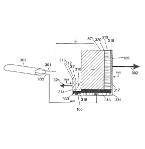
Figure 5a shows the distal end of coaxial cable 302, where first and
second conductive paths 300 and 301 are connected in parallel to ultrasonic
imaging transducer 105 and ultrasonic angle detecting transducer 100. For
minimally invasive imaging procedures, electrical cable 302 may be a micro-
coaxial cable or micro twisted pair with a diameter of less than about 1000
microns, or alternatively less than 500 microns. Excitation pulses are
transmitted to both ultrasonic transducers along signal wire 301, while a
second connection, optionally to ground, is provided by second wire 300. The
conductive paths of the channel, labeled as the signal (+) and ground (GND)
paths may be interchanged. Both transducers are shown in a side view.
Imaging transducer 105 may be larger in size than angle sensing
transducer 100, and imaging transducer 105 may possess a lower center
frequency than angle sensing transducer 100. In one example
implementation, the center frequency of imaging transducer 105 may be in the
range of 5-60MHz, while the center frequency of angle detection transducer
100 may be in the range of 25-100MHz. In another example embodiment, the
transducers differ in center frequency by a factor of at least about 2.5. In
one
embodiment, the factor is between about 2.5 and 3. In one specific and non-
limiting example, one transducer may have a center frequency of 15 MHz,
and the other transducer may have a center frequency greater than about 40
MHz.
31
CA 02824955 2013-07-17
WO 2012/103650
PCT/CA2012/050057
Imaging transducer 105 generally consists of a piezoelectric material
319, commonly PZT-5H, but may include other piezoelectric ceramics, a
composite design, a single crystal design, lithium niobate, PVDF and a variety
of other materials known for ultrasound transducer fabrication, including
cMUT and pMUT transducers. The piezoelectric is coated on both sides 318
and 320 with conductive layers, such as thin layers of gold or other materials
with high conductivity. On one side of the piezoelectric layer 319, a backing
layer 321 may be applied to dampen undesired acoustic signals from going
through the back of the transducer. The backing layer 321 may be electrically
conductive, as this simplifies an electrical connection with angle detection
transducer 100, as will become apparent below. In an alternative embodiment
in which the entire backing layer 321 and/or backing layer 310 is not
electrically conductive, suitable electrically connections between signal wire
301, conductive layer 320, and conductive layer 311, may be provided
through a conductive channel formed within backing layer 321 and/or backing
layer 310 or through a conductive wire connecting the conductive regions.
The signal conduction wire 301 is connected electrically to conductive layer
320, such as through a conductive backing layer 321. Alternatively, other
conductive paths between signal conduction wire 301 and conductive layer
320 can be used. In the example embodiment of Figure 5a, all regions
sharing the electrical connection to the signal conduction wire 301 are
labeled
with a "+" symbol. At one end of the transducer backing layer 321, an
electrically insulating barrier 331 is bonded to the transducer. On the face
of
the piezoelectric material 318 opposite the backing layer 321, a thin layer of
an electrically conductive acoustic impedance matching material 317 is
32
CA 02824955 2013-07-17
WO 2012/103650
PCT/CA2012/050057
bonded.
A thin and electrically conductive layer 316 is bonded adjacent to the
electrically insulated barrier 331. Ground connection 300 is connected
electrically to this layer. All regions sharing the electrical connection to
the
ground conduction wire 300 are labeled as "GND". The acoustic beam emitted
from the imaging transducer is directed along an axis normal to the transducer
surface 392.
Similar to the design of the imaging transducer 105, angle detection
transducer 100 consists of a piezoelectric material 312, commonly PZT-5H,
but may often include a composite design, a single crystal, lithium niobate,
or
PVDF and a variety of other materials known in the art. Piezoelectric layer
312 is coated on both sides 311 and 313 with a thin conductive layer,
commonly gold. On one side of piezoelectric layer 312, a backing layer 310 is
applied to damp out undesired acoustic signals from going through the back
of the transducer. Backing layer 310 may be electrically conductive and
electrically connected to backing layer 321. At one end of the transducer
backing complex, a thin electrically insulated barrier 330 is bonded to the
transducer. On the face of the piezoelectric material 312 opposite backing
layer 310, a thin layer of an electrically conductive acoustic impedance
matching material 314 is bonded. A thin electrically conductive layer 315 is
bonded adjacent to the electrically insulated barrier 330. The acoustic beam
emitted from angle detecting transducer 100 is directed along an axis normal
to the transducer surface 394. Alternatively, backing layer 310 may be omitted
and conductive layer 311 may be directly bonded to backing layer 321. In this
case, the two transducers may share backing layer 321 for damping out
33
CA 02824955 2013-07-17
WO 2012/103650
PCT/CA2012/050057
unwanted acoustic signals.
In order for the transducers to share electrical connections in an
embodiment in which the transducers form a unitary structure, they may be
mounted or bonded such that the conductive ground channels 315 and 316 of
each transducer are in direct electrical contact, the electrically insulating
barriers 330 and 331 are in continuity, and the backing layers 310 and 321 of
both transducers are electrically conductive and in direct contact with each
other. There should be high electrical resistance between the electrically
conductive signal regions and ground regions of either transducer in order to
.. maintain appropriate connections.
It is to be understood that the embodiment described in Figure 5a is
example of one of several embodiments wherein two ultrasound transducers
can share a single electrical channel and form a unitary structure. In an
alternative embodiment, one or more of the backing layers need not be
electrically conductive, provided that conductive pathways to opposing sides
of piezoelectric elements 312 and 319 for each of the transducers are
provided. Electrically conductive pathways can be made using materials such
as wires, metals, conductive epoxies and other materials known in the art.
The pathways may be made using processes such as, but not limited to,
layering, bonding, and soldering, sputtering, wire bonding.
Acoustic matching layers 314 and 317 may improve the efficiency of
acousto-electric coupling but may not be necessary for one or more of the
transducers. In an alternative embodiment, a plurality of matching layers may
be used for one or more of the transducers. Furthermore, electrically
insulating barriers 330 and 331 provide example embodiments for electrically
34
CA 02824955 2013-07-17
WO 2012/103650
PCT/CA2012/050057
isolating the signal and ground pathways from each other but may take on
more complex arrangements than described in Figure 5a, and may include a
void or gap made of an insulating gas or liquid rather than a solid material.
Furthermore, the signal and ground designations of each side of the two
transducers are arbitrary and can be connected in several permutations of
arrangements.
Figure 5b illustrates an embodiment for sharing a single electrical
connection between the angle detection transducer 100 and imaging
transducer 105 while the two transducers do not form a unitary structure. For
example, the transducers may be fabricated in the same way as described in
reference to Figure 5a, but are not bonded together. Instead, the signal
connection 301 and ground connection 300 from coaxial cable 302 are
connected electrically to opposing sides of the piezoelectric elements 313 and
319 both the angle detection transducer 100 and the imaging transducer 105.
In the example shown in Figure 5b, all regions sharing the electrical
connection to the signal conduction wire 301 are labeled with a "+" symbol.
Similarly, the ground connection 300 is connected electrically to both the
conductive path 315 on the angle detection transducer 100 and the
conductive path 316 on the imaging transducer 105. All regions sharing the
electrical connection to the ground conduction wire 300 are labeled as "GND"
in Figure 5b. In one example embodiment, the ultrasound transducers operate
at substantially different center frequencies.
In some embodiments, a multi-transducer imaging probe is provided in
which the imaging probe houses two or more ultrasonic imaging transducers
that are connected to a common electrical channel. Each transducer may be
CA 02824955 2013-07-17
WO 2012/103650
PCT/CA2012/050057
selected to exhibit a unique spectral response that is substantially
spectrally
distinct and non-overlapping from the other ultrasonic transducers. As noted
above, additional electrical filtering may be employed to provide additional
spectral isolation among the ultrasonic transducers.
The imaging transducers may be positioned to direct each ultrasonic
imaging beam in a distinct direction, thereby enabling simultaneous imaging
at multiple angles. Unlike phased array imaging, in which multiple ultrasonic
transducers are driven in a phased relationship by unique and individual
electrical channels, the present embodiment enables multi-transducer, multi-
angle and/or multi-frequency imaging based using a single electrical channel
upon which the signals for exciting the different transducers are multiplexed.
In one example embodiment, two or more imaging transducers may be
oriented to direct their ultrasonic imaging beams in a substantially common
direction, which may be useful, for example, for simultaneous imaging in
multiple acoustic spectral windows. In other embodiments, as shown below,
three or more transducers can be used to form unitary structures similar to
those shown in figures 5c and 5d, and that multiple transducers can be
oriented at arbitrary angles with respect to each other.
Figures 5c and 5d show two example embodiments in which an
imaging probe houses two imaging transducers oriented with a relative angle
of 180 and 90 , respectively. Transducers 399 and 397 are electrically
connected via common coaxial conductor 302 (comprising common ground
wire 300 and common signal wire 301), and are shown as housed within
sheath 43. Connections to the suitable conductive layers of transducers 397
and 399 may be made, for example, as shown in Figure 5a. It should be noted
36
CA 02824955 2013-07-17
WO 2012/103650
PCT/CA2012/050057
that conductive paths within the unitary structure can be configured such that
conductive paths 300 to 301 connect to a common side of the unitary
structure, or in various other arrangements such that the electrical
connections within the unitary structure provide appropriate conductive paths
to transducers 397 and 399. In other example implementations, the
connections to the conductive layers of the transducers may be made, as
described above, using materials such as wires, metals, conductive epoxies
and other materials known in the art, and pathways may be made using
processes such as, but not limited to, layering, bonding, soldering,
sputtering,
wire bonding.
Figure 5c demonstrates a catheter housed in a sheath 43 configured
for side-viewing imaging with a unitary structure formed by joining ultrasound
transducers 397 and 399. Here, transducers 397 and 399 transmit anti-
collinear beams, 393 and 395 respectively, in a generally side viewing
direction relative to the longitudinal axis of the catheter. Upon a complete
revolution of the distal imaging assembly, both transducers will have imaged
the same region in tissue. This arrangement may be useful in a situation
where it is desired to image the same region of tissue with two different
frequencies, often a low frequency for deep penetration and a higher
frequency to achieve high resolution. While this embodiment shows beams
393 and 395 being anti-collinear, other useful embodiments would include
beams that are anti-parallel, but not necessarily anti-collinear.
Similarly, Figure 5d shows an example implementation in which
ultrasound imaging transducers 397 and 399 are both in a generally side
viewing direction while transmitting substantially orthogonally directed beams
37
CA 02824955 2013-07-17
WO 2012/103650
PCT/CA2012/050057
with the centers of the transducer apertures positioned at approximately the
same position along the probe's longitudinal axis. Upon a complete revolution
of the distal imaging assembly, both transducers will have imaged the same
region in tissue.
Figures 5c and 5d provide two non-limiting embodiments of imaging
probes housing dual transducers that are electrically addressable via a
common electrical channel, for which many other related embodiments and
design variations are possible. For example, any of the embodiments of the
present disclosure involving tiltable, pivotable, rotatable and movable
elements for directing an emitted imaging beam may be adapted to further
include a second imaging transducer according to the present embodiment,
where the second imaging transducer need not necessarily be physically
contacted with the first imaging transducer.
In some embodiments, the second imaging transducer may be
positioned or oriented to have a field of view remote from the first imaging
transducer. Alternatively, the first and second imaging transducers may have
fields of view that overlap to create a combined field of view, wherein the
signals from one transducer may be used to provide ultrasound data for one
portion of the combined field of view and signals from the second transducer
are preferentially used to provide ultrasound data for another portion of the
combined field of view. Ultrasound data from each of the one or more
transducers may be used for any of several purposes, including imaging,
tissue characterization, sensing of instruments outside the imaging probe, and
sensing movement of components within the image probe.
For example, in the embodiments shown in figures Sc and 5d, a
38
CA 02824955 2013-07-17
WO 2012/103650
PCT/CA2012/050057
transducer with a first center frequency may be used for imaging more distant
regions in the combined field of view, while a second transducer with a lower
center frequency than the first transducer may be used for providing higher
resolution imaging data in regions closer to the imaging catheter.
Furthermore, such embodiments may optionally include one or more angle
sensing ultrasonic transducers for detecting the direction of an ultrasonic
imaging beam emitted by the first and/or second imaging transducers, where
the angle sensing transducers are also connected to the common electrical
channel.
Figure 5e shows a scenario where one imaging transducer 387 is
shaped such that it contains features that allow for the mounting of a second
transducer 397 at an oblique angle relative to the longitudinal axis of the
imaging probe. When the distal imaging assembly is rotated, transducer 387
will image a largely side-viewing region of tissue, while transducer 397 will
image a partially forward viewing conical region of tissue.
Figure 5f shows a configuration of a unitary structure of multiple
ultrasound transducers driven on a single channel suitable for situations
where multiple collinear imaging beams are desired. In the embodiment show
in the Figure, a lower-frequency beam 389 is transmitted from transducer 391
in parallel with a higher-frequency beam 392 from transducer 397. Transducer
397 also receives corresponding echoes.
The embodiment shown in Figure 5f may be employed for second
order ultrasound field (SURF) imaging. SURF imaging uses acoustic energy
in two distinct frequency bands transmitted simultaneously. The energy in one
frequency band is generally at a low frequency (a center frequency in the
39
CA 02824955 2013-07-17
WO 2012/103650
PCT/CA2012/050057
range of 0.5-10MHz) and is used as a modulation or manipulation pulse. The
energy in the high frequency band tends to be centered approximately 7-10
times higher than the center frequency of the low frequency band. The high
frequency energy band is employed to image the tissue under different
modulation pressures, as generated but the modulation or manipulation pulse.
Accordingly, referring to Figure 5f, ultrasound transducer 397 may be
employed to provide a high frequency imaging beam, while larger ultrasound
transducer 391 may be provided to generate a SURF ultrasound beam that is
parallel and substantially collinear to the imaging beam. While this technique
has been performed with two separate ultrasound transducers with two
separate electrical channels, the present embodiment may be performed to
achieve SURF imaging with a single electrical channel.
It may also be desirable to include more than two imaging transducers
on the same unitary structure connected by a single electrical channel. Figure
5g shows a configuration including three ultrasound transducers, each of
which is characterized by a different center frequency. An example of an
application for such an embodiment is again for SURF imaging. A low
frequency manipulating beam 389 is transmitted from transducer 391 and
used to modulate tissue being imaged, while a higher frequency imaging
beam 392 is emitted from transducer 397 in a direction that is collinear to
modulating beam 389. Positioned to create an antiparallel, and, in some
embodiment, anti-collinear, beam 381 is another transducer 379. The
frequency of beam 381 may be selected to be higher than that of imaging
beam 392 to provide high resolution imaging. One example of a suitable set of
frequencies is a 3MHz modulating beam 389, a 25MHz SURF imaging beam
CA 02824955 2013-07-17
WO 2012/103650
PCT/CA2012/050057
392, and a 60MHz high frequency imaging beam 381.
It may also be desirable to combine multi-frequency transducers with
other imaging modalities. One potential family of modalities is fiber
compatible optical imaging modalities. These may include optical coherence
tomography, fluorescence imaging, photoacoustic imaging, angioscopy,
Raman spectroscopy and other optical modalities known in the art. Figure 5h
shows one such configuration including a unitary structure having three
components: (1) an ultrasound transducer 399 having a first center frequency,
(2) a second ultrasound transducer 397 having a second center frequency
that is different from the first center frequency, with both ultrasonic
transducers connected to a common electrical channel, and (3) an optical
imaging system 383 configured to generate optical imaging beam 385. In the
example embodiment shown in the Figure, the second ultrasound transducer
397 contains a hole and an optical beam director to allow optical imaging
beam 385 to emerge substantially collinear with second ultrasound imaging
beam 395.
While the imaging transducers shown in Figure 5 are shown as flat
transducers, one or more of them may be curved to provide beam focusing. In
many applications, it may be beneficial to provide a focused ultrasound beam,
or beams, for improved lateral resolution at a desired depth. It may
specifically
be desirable to focus higher frequency ultrasound beams at regions of interest
that are closer to the imaging assembly, and to focus lower frequency
ultrasound beams at regions of interest further from the imaging assembly.
This enables lateral resolution high resolution images at multiple depths,
giving an effectively improved depth of field. In this case, the highest
lateral
41
CA 02824955 2013-07-17
WO 2012/103650
PCT/CA2012/050057
resolution would be achieved close to the imaging probe, where it is often
desired for a number of imaging or image guided procedures such as crossing
CT0s, vulnerable plaque detection, or transseptal puncture. An embodiment
showing focused transducers is shown in Figure 5i, where a first, low
frequency transducer 373 is curved to focus at a depth 375 with acoustic
beam 374. A second, high frequency transducer 376 has its acoustic beam
377 focused to a depth 378, which is closer to the imaging probe than 375.
There are multiple ways of achieving focus on an ultrasound transducer,
including using acoustic lenses, mechanical pressing, machining of a curved
surface, or using a flexible piezoelectric such as PVDF or a composite
material that can be formed into a curved surface.
As noted above, in some example embodiments, excitation pulses and
detected signals are respectively transmitted to and received from both
transducers on a common electrical channel, while enabling the detected
signals from each transducer to be separated or demultiplexed for image
processing and/or angle determination. There are numerous techniques that
can achieve this without departing from the scope of the present embodiment.
Selected techniques involve separating the frequency spectra of the imaging
signal information and the angle detection signal information.
One embodiment for demultiplexing both detected signals is illustrated
in Figure 6. The center frequencies of both transducers are selected such that
there is substantially little or no overlap between the respective transducer
spectral bandwidth ranges 396 and 398. If the transducers are adequately
separated in terms of frequency spectra, signals from one transducer will not
interfere with signals from the other. That is, in the illustrative context of
an
42
CA 02824955 2013-07-17
WO 2012/103650
PCT/CA2012/050057
embodiment involving an imaging transducer 105 and an angle detection
transducer 100, an imaging pulse sent to the imaging transducer 105 will not
cause a significant acoustic response from the angle detection transducer
100.
Common definitions of spectral bandwidth in ultrasound are based on
the range of frequencies surrounding a peak amplitude of the frequency
domain representation of an acoustic or electrical signal generated or
detected by an ultrasound transducer. In one embodiment, the spectral
bandwidths are at least 6 dB bandwidths. For example, the 6dB spectral
bandwidth typically refers to the range of frequencies surrounding a frequency
of a peak amplitude in which the amplitude of the signal across that range of
frequencies is within 6dB of the peak amplitude. The 20dB and 40 dB
spectral bandwidths are also commonly used.
An example frequency spectrum 396 of imaging transducer 105 and an
example frequency spectrum 398 of angle detection transducer 100 are
plotted in Figure 6 such that the 6dB points of both transducers intersect
with
the x-axis. Similarly, an angle detection pulse sent to the angle detection
transducer 100 will not cause a significant acoustic response from the imaging
transducer 105.
The frequencies of the two transducers may be selected to avoid
harmonics of the transducer center frequencies. In general, it may be
advantageous to avoid having the center frequencies of the transducers as
integral multiples of one another, so as to avoid confusion caused by
harmonics from non-linear echoes. This is especially true for cases where
.. microbubble specific imaging techniques are being used, as many of these
43
CA 02824955 2013-07-17
WO 2012/103650
PCT/CA2012/050057
techniques rely on harmonics for separation between tissue and contrast
agent. The higher frequency transducer may be configured to have a larger
absolute bandwidth to take advantage of increased axial resolution at the
higher frequency, as shown.
In some circumstances, imaging excitation pulses may possess a
significantly broader bandwidth than that of the imaging transducer, thereby
resulting in the possibility of transmitted pulses spectrally overlapping with
the
bands of both transducers. This may be mitigated using analog or digital
filtering techniques to separate the effective bands of the excitation pulses
received by the individual transducers.
In one embodiment, such a filtering scheme may be implemented using
passive elements as shown in Figure 7. A filter 380 may be generated from a
combination of electrical components, such as resistive, inductive and/or
capacitive components, and is employed to spectrally restrict imaging pulses
from exciting the angle detection transducer 100, while a filter 390 may be
generated from a combination of electrical components to spectrally restrict
angle detection pulses from exciting the imaging transducer 105.
Alternatively,
narrower band excitation pulses can be used for imaging, angle detection or
both.
In another example embodiment, in which both transducers are
spectrally isolated as shown in Figure 6, a broadband excitation pulse or
waveform may be provided that overlaps the spectral bandwidths of both
transducers, or the excitation waveform may include a first spectral
component that is within the bandwidth of one transducer, and a second
spectral component that is within the bandwidth of another transducer.
44
CA 02824955 2013-07-17
WO 2012/103650
PCT/CA2012/050057
Detected signals are demultiplexed in the frequency domain using
spectral filtering techniques to individually resolve the signals detected
from
each transducer. Spectral filtering of the detected signals may be
implemented using either analog or digital filtering, or both. For example,
the
signal from the single electrical channel can be separated using analog
filters
to two separate receive channels that may be connected to two separate
analog to digital converters in image processing and display system 49.
Alternatively, digital spectral filtering can occur on digitally sampled
representation of the received signal using a single analog to digital
converter
where digital processing hardware or software, are used to separate the
imaging and angle detection data.
Figure 8 illustrates an embodiment in which tiltable member 150 is
configured to reflect incident radiation from imaging transducer 105, and
where the angular deflection of tiltable member 150 is detected using a time
.. of flight method. In this case, imaging transducer 105 is mounted at a
fixed
location and oriented towards the tiltable member 150.
As shown in the figure, another imaging transducer or imaging
radiation source 103 can be mounted adjacent to, attached to, or transmitting
through a hole bored into the imaging transducer 105 as described in US
Patent Publication No. 20080177183. For example, an optical imaging
source/receiver 103 could be mounted to ultrasound imaging transducer 105
to provide a second imaging modality within an imaging probe. It is to be
understood that it is not necessary that the front surface of reflective
tiltable
member 150 is the same as the back surface of the reflector 153. The front
surface 151 may be constrained to being highly optically and/or acoustically
CA 02824955 2013-07-17
WO 2012/103650
PCT/CA2012/050057
reflective, while it may be desirable for the back surface 153 to be a diffuse
acoustic reflector and/or scatterer.
Figures 8a and 8b illustrate a common embodiment with tiltable
member 150 shown at two different tilt angles, where tiltable member 150 is
.. rotatably mounted on pivot axis 152. Angle detection transducer 100 is
placed
at a fixed location relative to pivot axis 152. Imaging transducer 105
transmits
an acoustic beam 120, while optical imaging source 103 transmits an optical
beam 130, where both acoustic beam 120 and optical beam 130 are
transmitted in a direction towards the front surface 151. Angle detection
.. transducer 100 transmits an acoustic beam 110 towards the back surface 153
of tiltable member 150, and a portion of the beam is reflected back towards
the angle detection transducer 100. This may be achieved via diffusive
reflection of the incident ultrasonic angle sensing beam.
In Figure 8a, tiltable member 150 is relatively far from the angle
.. detection transducer 100, along the path of beam 110, when compared to
Figure 8b. This results in the angle detection beam 110 having a shorter time
of flight in Figure 8b than Figure 8a. The tilt angle can be calculated as
described above in reference to Figure 4. Timing diagrams are presented for
each angle scenario. A pulse is transmitted at t=0 with a high amplitude and
.. received at a later time, typically with a reduced magnitude. Figure 8e
shows
a sample plot of time delay, or time of flight vs. imaging angle. Figures 8c
and
8d are timing diagrams are presented for each angle scenario in Figures 8a
and 8b, respectively. The received pulse 502 corresponding to the signal
from Figure 8a has a much greater time delay that the received pulse 504
.. corresponding to the signal from Figure 8b.
46
CA 02824955 2013-07-17
WO 2012/103650
PCT/CA2012/050057
Figures 9a-9e illustrate an embodiment in which the change in angle of
a tiltable member, such as ultrasonic imaging transducer 105 is detected
using a time of flight method. This embodiment is similar to that of Figure 7,
except that ultrasonic imaging transducer 105 is not mounted on a pivoting
axis, and is instead mounted on a deformable member 112 whose
deformation is responsible for the tilting of the tiltable member.
Figures 10a-10e illustrates an embodiment in which the change of
angle of tiltable member 101 (shown as an imaging transducer) is detected
using a signal intensity method. This method is based on the relationship
between the intensity of diffusively scattered ultrasonic radiation and the
tilt
angle, where the reflected signal will be strongest when the angle detection
beam 110 is perfectly normal to tiltable member 101, as shown in Figure 10a.
As the tilt angle changes from normal, the strength of the received signal is
reduced (item 504 vs. item 502), as is seen in Figures 10c and 10d. The
reduction in received signal intensity or voltage can be used to estimate the
tilt
angle, as shown in the example calibration curve provided in Figure 10e.
Figures 10c and 10d are timing diagrams presented for each angle
scenario in Figures 10a and 10b, respectively. It is noted that there may be
temporal broadening of the signal due reflections coming from different
slightly different depths as the imaging transducer 101 is moved away from
being normal to the angle detection beam 110. Such an effect is shown in
Figure 10d. Accordingly, in selected embodiments, the relative temporal
broadening may also be employed to provide feedback relating to the
deflection angle. Such an embodiment may be used to confirm and/or
improve the accuracy of the deflection angle obtained through intensity
47
CA 02824955 2013-07-17
WO 2012/103650
PCT/CA2012/050057
measurements.
In some embodiments, the sensitivity of angle detection may be
hindered at large deflection angles due to intensity reduction, as illustrated
in
Figure 10. The intensity of a received signal from a perfect reflector drops
very quickly from angles even slightly off normal from the angle detection
beam 110. This makes the signals very difficult to detect, and diffusive
reflectors may provide improved performance. There are several potential
approaches to overcoming this.
The difference between a specular and diffusive reflector is illustrated
in Figures 11a-d. Figure lla shows a specular reflective tiltable member 170
receiving an angle detection beam 110 from an angle detection transducer
100. The beam is reflected off the specular reflector 170, and the reflected
beam 113 is directed in a path that is not co-incident with the angle
detection
transducer. The result, as shown in the timing diagram below in Figure 11c, is
that the pulse is not received.
Figure llb illustrates an embodiment in which the incident beam 110 is
reflected by a diffusive reflector. While a portion of the beam 117 may be
directed away in a similar fashion as described in Figure 11a, a significant
portion of the beam 115 is scattered and diffusively reflected over a wide
angular range. A portion of this beam is collinear with the incident beam 110,
thus allowing for a time of flight detection technique to be feasible (as
shown
in Figure 11d by the presence of the reflected pulse).
Another potential arrangement that can assist with the reduction of
signal from a substantially specular reflector is the use of multiple angle
detection transducers. Such an embodiment is illustrated in Figures 12a-12d.
48
CA 02824955 2013-07-17
WO 2012/103650
PCT/CA2012/050057
Here, two angle detection transducers 100, 126 are oriented towards tiltable
member 101 which is mounted on pivot axis 102. Each of the angle detection
transducers 100, 126 generate their own acoustic beam 110, 127.
All 3 transducers of the preceding embodiment may be driven by a
single electrical channel (for example, connected to patient interface module
36 of Figure 1). Notably, there will be an overlap in the received signals
from
the angle detection transducers 100, 126 if they lie within the same frequency
range. This can be resolved with prior knowledge of the transducer positions,
or by limiting the range of angles through which the tiltable member is
allowed
to tilt.
The distance calculated by the time of flight difference between the two
received pulses may provide tilt angle information in this case. For instance,
if
the two angle detection transducers 100, 126 are placed 900 from each other
with one of the beams parallel to the longitudinal axis, equidistant from
pivot
axis 102 and on opposing sides of pivot axis 102 but the same side of tiltable
member 101 with a flat surface (as they are in Figure 12), the difference in
the
time between the received pulses from both transducers will be at a minimum
when the tilt angle is 45 from the longitudinal axis (As suggested by Figures
12c and 12d). As the tilt angle moves away from 45 , the time between the
received signals between the two transducers will increase, as shown in
Figure 12d with received pulses 510, 512 from angle detection transducers
100, 126 respectively.
Angle sensing transducers 100 and 126 may be selected to have
substantially non-overlapping spectral bandwidths, thus allowing the
individual
detected signals to be separated based on their frequency domain content.
49
CA 02824955 2013-07-17
WO 2012/103650
PCT/CA2012/050057
Alternatively, one of the angle sensing transducers may be placed further
away from tiltable member 101 than the other, thus ensuring that the time
delays from each of the angle sensing transducers is distinct from the time
delay detected by the other angle sensing transducer.
Alternatively, knowledge of the expected direction and / or degree of tilt
of the tiltable member can be used to algorithmically determine which portions
of the sensed signal along the single electrical channel correspond to each of
the two or more angle sensing transducers. For example, in the example
implementation of an imaging probe having a movable member with an
angular orientation that is dependent on the rotational speed of a rotational
conduit housed within the imaging probe, if the rotational speed of imaging
assembly 50 along the longitudinal axis of imaging probe 44 is increased, it
may be expected that the tiltable member would tilt in a more forward looking
direction. Therefore, knowledge of the expected direction of tilt could be
used
to identify which of the peaks in the received signal corresponds to one of
the
several angle sensing transducers. Similarly, knowledge of the instantaneous
rotational velocity of the imaging assembly may correspond with a greater
likelihood to a particular range of tilt angles, and such a relationship could
be
used to identify which of the peaks of the received signal most likely
corresponds to one of the several angle sensing transducers.
Figures 13a-13e illustrates an embodiment that enables sensitive
angular detection while increasing the range of angles that can be detected by
the angle detection transducer 100. In this embodiment, the back surface of
tiltable member 183 (which may also include an imaging transducer, as
shown in Figure 13) has been shaped with a series of curved indentations. As
CA 02824955 2013-07-17
WO 2012/103650
PCT/CA2012/050057
the transmitted beam 110 hits the back of tiltable member 183, a small portion
of the reflective interface will be substantially normal to the incident beam
110,
causing part of the beam 181 to be reflected back to angle detection
transducer 100. Accordingly, the angle can be resolved using a time of flight
method similar to Figure 4. It is to be understood that the specific
cylindrical
surface patterning illustrated in Figure 13 is merely one non-limiting
embodiment, and that a wide range of surface profiles may be employed to
achieve a similar result according to the present embodiment. For example,
parabolic cross-sections, or a pattern of divots may be used on the back
surface of tiltable member 183.
While the preceding embodiments have disclosed surfaces that are
diffusively reflective, it is to be understood that diffusive reflections may
be
generated by surface and/or volume material properties. For example,
particles of metals, ceramics, silicon dioxide, graphite, glass beads, or
other
compounds known in the art can be added to a material or surface to make it
more diffusely reflective.
The use of composite materials or flexible polymers has allowed for
ultrasound imaging transducers to be shaped physically. Such transducers
may be employed for focusing acoustic energy. Alternatively, acoustic lenses
may also be used to focus acoustic energy. However, such schemes may be
adapted to the present embodiments to broaden the acoustic beam and
support an increase in the range of angles that can be detected. This is
illustrated in Figures 14a-14d, where angle detection transducer 200 is curved
such that it creates diverging beam 210. As shown in the Figure, a portion of
the beam is normal to the imaging transducer 101 at a wide range of angles.
51
CA 02824955 2013-07-17
WO 2012/103650
PCT/CA2012/050057
The normal portion of the beam 220 is reflected back to the transducer, even
when the tiltable member is a specular reflector, and may be measured to
estimate tilt angle using a time of flight method as in Figure 4.
Yet another embodiment for increasing the range of angles that can be
detected may be achieved by attaching the angle detection transducer to the
tiltable member. Figures 15a-15e shows an example of one such
embodiment. In this embodiment, angle detection transducer 100 is mounted
to the back of the tiltable member 101. The angle detection beam 110 is
directed towards stationary reflector 174. A portion of stationary reflector
174
may be curved (in any of several shapes) to provide a suitable angle-
dependent acoustic reflection profile. Example yet non-limiting curvature
profiles include circular, elliptical or parabolic shapes.
In one embodiment, the stationary reflector 174 may be shaped so that
over a wide range of imaging transducer 101 tilt angles, the reflection from
the
angle detection beam 110 is largely retro-reflected towards the angle
detection transducer 100. As shown in Figures 15c and 15d, one or both of
the time of flight and intensity schemes may be employed to infer changes in
the orientation of tiltable member 101.
Figure 15e describes one method to design a stationary retroreflecting
acoustic reflector. The angle detection transducer 100 is modeled in a
forward viewing position, as defined by tilt axis 600. A desired distance 608
between angle detection transducer 100 and the reflecting surface is chosen
and a data point is generated on a line normal to transducer 100 a distance
608 away from transducer 100. The angle detection transducer is tilted by
angle 616 about pivot point 102 and desired distance 610 between angle
52
CA 02824955 2013-07-17
WO 2012/103650
PCT/CA2012/050057
detection transducer and reflecting is chosen to differ from 608 by a selected
amount, such as an amount for obtaining a desired angular resolution. A data
point is generated as with the above. This process is repeated until the angle
detection transducer is tilted to the point that it is side viewing. A
continuous
surface 601 is defined by interpolating the data points generated as described
above using known curve fitting techniques. Examples of suitable curves that
can be fitted are portions of an ellipse, parabola, circle, hyperbola,
exponential, roulette, or polynomial using fitting strategies common in the
art
including but not limited to ordinary least squares or total least squares.
Once a surface is defined and fabricated, there may be imperfections
in machining tolerances and misalignments in assembly among other
uncertainties. In order to mitigate this, calibration of an angle detection
assembly may be used to overcome these imperfections.
According to another embodiment, the surface 601 is defined such that
the angle detection beam emitted by the angle sensing ultrasonic transducer
100 is substantially retroreflected over a given range of pivot angles, such
that
the distance between surface 601 and angle sensing ultrasonic transducer
100 varies monotonically over the range of pivot angles, and such that the
rate of change of the relative distance with respect to the pivot angle
(which,
at least in part, determines the resolution of the apparatus), exceeds a
minimum value over the range of pivot angles. In one embodiment, surface
601 is configured such that the rate of change of the relative distance with
respect to the pivot angle is substantially constant over the range of pivot
angles, such that the sensitivity of the apparatus is substantially
independent
of pivot angle over the range of pivot angles.
53
CA 02824955 2013-07-17
WO 2012/103650
PCT/CA2012/050057
As noted above, in some embodiments, the angle of the detection
beam may be constrained to remain approximately normal to the reflective
surface of the tiltable member, thereby generating a retroreflection. This
eliminates the need to compensate for reflections at angles where the angle
detection beam is not normal to the tiltable member, and generally results in
detected beam of higher intensity. Example embodiments utilizing such an
approach are shown in Figures 16 and 17. Figures 16 a-d illustrate an
embodiment in which angle detection transducer 100 is mounted onto second
tiltable member 114 that is mechanically linked or coupled to first tiltable
member 101 via coupling mechanism 176. Secondary tiltable member 114 is
not necessarily acoustically active (and may be acoustically passive) and
allowed to pivot about axis 104.
Since both members are able to pivot about their own pivot axes and
are mechanically coupled, they will tilt in unison. The tiltable members are
mechanically coupled such that they tilt with a substantially equal tilt angle
during operation. A number of techniques may also be used to couple the
motion of the tiltable members, including, but not limited to, rods, beams,
magnets, and electromagnetic devices. The embodiments shown in Figures
16 and 17 have the additional benefit of adding another tiltable member to the
system that may not suffer from inertial or other design constrains of the
first
tiltable member, such as being an ultrasound transducer optimized for
acoustic performance.
Such a scheme may be useful in cases where first tiltable member
includes an ultrasonic imaging transducer, but does not possess suitable
characteristics for external rotational actuation. By incorporating secondary
54
CA 02824955 2013-07-17
WO 2012/103650
PCT/CA2012/050057
tiltable member 114 with characteristics designed for actuation via external
rotation and mechanically linking both tiltable members, first tiltable member
101 can be actuated based the behavior of second tiltable member 114. For
example, as shown in Figures 4f and 4g, ultrasound transducers may have
similar or larger dimensions in the range direction compared to the elevation
directions. This is largely due to the requirement for backing on an
ultrasound
transducer to attenuate signals in directions other than the desired imaging
direction. Bodies of this geometric configuration are not ideal for actuation
via
external rotation, as shown in Figures 4f and 4g.
Figure 4f shows a body 134 that has a similar dimension in the range
direction relative to the elevation direction. Here, the body pivots about
point
137 under rotation in direction 63. If the body is broken into two components,
one above longitudinal axis 131 and one below, the center of mass of the
components above and below longitudinal axis 131 are shown at 136 and 133
respectively. The centripetal force vectors are shown as 135 and 132
respectively.
Now, comparing to a body shown in Figure 4g, where the dimension in
the range direction is much smaller than the dimension in the elevation
direction, we see similarly that the body pivots about point 121 under
rotation
in direction 63. If the body is broken into two components, one above
longitudinal axis 122 and one below, the center of mass of the components
above and below longitudinal axis 122 are shown at 124 and 128 respectively.
The centripetal force vectors are shown as 129 and 123 respectively. The
result is that the pivotally mounted body 125 in Figure 4g has a much stronger
relative component of centripetal force that acts to cause tilt about the
pivot
CA 02824955 2013-07-17
WO 2012/103650
PCT/CA2012/050057
point 121 than body 134 does about pivot point 137.
This mechanical coupling may also allow angle detection beam 110 to
remain normal to the ultrasound imaging transducer 101. Other techniques
that additional deflectable member can employ to assist in deflection may
include the use of hydrofoil features or artificial muscle actuation.
A time of flight technique can be used to estimate the imaging angle,
similar to that shown in Figure 4. Alternatively, or additionally, an
intensity
measurement method may be employed, as illustrated in Figures 10c and
10d.
Figure 16e illustrates some of the parameters that may be employed to
calculate the tilt angle 0 based on measured distance 400. If the distance 401
between acoustically passive disc 114 and the imaging transducer 101 is
constant and known a priori, and the distance between the angle detection
transducer 100 and the imaging transducer 101 is determined with the
knowledge of the signal time of flight and the speed of sound in the medium,
the angle can be calculated with the trigonometric equation 0 =
arcCos(measured distance 400 / known distance 401).
In a similar embodiment, illustrated in Figures 17a-17d, angle detection
transducer 100 can be mounted on the tiltable member 101, and maintained
in a normal orientation relative to acoustically passive tiltable member 114.
A
unitary structure similar to that shown in Figure 5a would be suitable for use
as the tiltable member 101 in Figure 17a.
Figure 18a illustrates an embodiment that combines the features
shown in Figures 15 and 17. Here, the stationary curved reflector 174 is
employed to increase the range of angles that can be detected using the
56
CA 02824955 2013-07-17
WO 2012/103650
PCT/CA2012/050057
angle detection transducer 100. This is achieved by separating the imaging
transducer 101 and the acoustically passive tiltable member 114 in space
sufficiently such that they do not come into contact with each other
regardless
of tilt angle (within the range permitted during operation), while still
allowing
the acoustically passive second tiltable member 114 to be employed to assist
the ultrasound imaging transducer 101 in achieving desired motion using
mechanical coupler 176.
Figure 18b shows a view cut of an example embodiment through the
hatched line in Figure 18a. A notch 177 in the stationary curved reflector 174
.. is created such that the mechanical coupler 176 is allowed to pass through
the stationary reflector 174 unimpeded. By way of example, mechanical
coupler 176 may include a simple bar or rod that is connected to each of the
tiltable members 114 and 101 by a hinge or other mechanism, such as a
mechanism that creates a pivot point or deformable joint between mechanical
coupler 176 and each of the tiltable members.
Figures 18 c-i demonstrate another apparatus for detecting tilt angle
where the angle detection transducer 100 is mounted inside the notch 177 of
supporting structure 175 instead of being attached to the tiltable member 101.
Figures 18c and 18e show the setup at two different tilt angles. Cut view
.. through the hatched lines in Figure 18c and 18e are shown in Figures 18d
and 18f respectively. Figures 18g and 18h show the timing diagrams for
Figures 18d and 18f respectively. In Figure 18d, the mechanical coupling bar
176 is near the top of the notch 177 resulting in the received signal in 18g
having a long delay, whereas in Figure 18f it is considerably further down
within the notch, and is subsequently closer to the angle detection transducer
57
CA 02824955 2013-07-17
WO 2012/103650
PCT/CA2012/050057
resulting in a received signal with a shorter time delay. Figure 1 8i shows a
plot
estimating deflection angle vs. time delay. Alternatively, the angle detection
transducer 100 can be mounted on mechanical coupling bar 176 and pointed
towards the bottom of notch 177.
Figures 18c-i show how a second transducer 100 can be used to
detect the position of a component within an imaging probe. While the
position information may be used to infer the tilt angle of a tiltable
component,
the ability to more generally gather information about the position of a
movable component within an imaging probe by using a second transducer
that shares a common single channel with another ultrasound transducer
becomes apparent.
Although Figure 18 provides one example embodiment in which an
additional ultrasonic transducer is employed for detecting changes in a
position of a movable component, it is to be understood that this embodiment
may be employed in a wide number of applications for detecting motion of a
component within an ultrasonic probe. Other illustrative examples in which the
motion of a component may be detected include features in the sheath during
a pullback operation, a retractable sheath, the presence of bubbles, a change
in fluid density in the catheter, or a therapeutic tool such as a
Brockenborough
needle.
Accordingly, it is to be understood that the scope of the embodiments
disclosed herein is not to be limited to those in which an angular orientation
or
a change in an angular orientation of a movable component is determined
using one or more additional ultrasonic transducers, and further encompasses
.. embodiments in which a position or a change in position of a movable
58
CA 02824955 2013-07-17
WO 2012/103650
PCT/CA2012/050057
component is determined using one or more additional ultrasonic transducers,
irrespective of whether or not the position or change in position relates to
an
angular orientation or a change in angular orientation.
Figure 19 shows an example time-domain imaging and angular
detection sequence for a single pulse-echo ultrasound imaging sequence
using the embodiment described in Figure 17. In Figure 19a, imaging
transducer 101 is excited with a low frequency pulse, as shown in the timing
diagram shown in Figure 19b. The pulse generates an acoustic beam 120
which propagates until it reaches an object 106 in its path.
Part of the beam is reflected, and detected by the imaging transducer, and as
a result displayed in the "Receive" portion of the timing diagram. Next, the
residual beam meets another object 108, and again, a part of the beam is
reflected, and detected by the imaging transducer and likewise appears as a
received signal, slightly further along the "Receive" timing diagram.
After imaging data is received, a high frequency angle detection pulse
is transmitted down the same channel, generating an acoustic beam 110 from
the angle detection transducer 100. This beam is reflected off the
acoustically
passive member 114 and returned to the transducer. The tilt angle is
determined using the time of flight of the beam 110 following the high
frequency pulse generation.
As described above, this embodiment can be optionally aided with the
use of one or more electronic filters to select the desired frequency
components. For example, a low pass filter may be used to emphasize low
frequency signals from the low frequency imaging transducer 101 following
transmission of an imaging pulse 550, while a high pass filter may be used to
59
CA 02824955 2013-07-17
WO 2012/103650
PCT/CA2012/050057
emphasize the high frequency signals from high frequency angle detection
transducer 100 following the transmission of angle detection pulse 500. These
filters may reside within the imaging probe, or optionally external to the
imaging probe, such as within controller and processing unit 34 or patient
interface module 36.
Figure 19c-e shows an embodiment where both transducers are
excited with a broadband pulse that covers the bandwidths of both imaging
transducer 101 and angle detection transducer 100. The received signal from
both transducers is demultiplexed in order to separately process the imaging
signal data and the angle sensing data. Such demultiplexing may be achieved
according to one of many embodiments.
In one such discriminatory embodiment, as described in Figure 19d, a
time domain method is employed utilizing the fact that there may be a
significant difference in the distance between a) the angle detection
transducer 100 and the second deflectable member 114 and b) the imaging
transducer 101 and the acoustic imaging targets 106 and 108.The distance
between the angle detection transducer 100 and the second deflectable
member 114 may be significantly less than the distance between the imaging
transducer 101 and the acoustic imaging targets 106 and 108. In this
arrangement, signals received 558 shortly after transmission 560 pulse is sent
may be deemed to be as a result of the angle detecting transducer 100, and
signals received after later time delays 554, 556 may be deemed to be as a
result of the imaging transducer 101. Accordingly, in such an embodiment, all
pulses received prior to the vertical hatched line 562 are deemed to be angle
detection pulses and those received after are deemed to be imaging pulses.
CA 02824955 2013-07-17
WO 2012/103650
PCT/CA2012/050057
A second embodiment for demultiplexing the signals may be achieved
by spectrally filtering or separating the spectral content contained within
the
net signal and can be achieved using the same embodiment shown in Figure
19c. A representative timing diagram is shown in Figure 19d as described
above. Since the bandwidths of the transducers are sufficiently separated
and may be known, signals falling within the bandwidth of the angle detection
transducer 100 can be deemed to be originating from the angle detection
transducer 100, and signals falling within the bandwidth of the imaging
transducer can be deemed to be originating from the imaging transducer.
This spectral separation is shown the spectral plot in Figure 19e, where
the vertical hatched line 564 is used to show a point representing the
separation between imaging data and angle detection data. This line may be
the midpoint between the center frequencies of the two transducers. All
spectral components lower than the frequency represented by the hatched
.. line are deemed to be components of the imaging signal 568, and all
spectral
components higher than the frequency represented by the hatched line are
deemed to be components of the angle detection signal. Also, the separation
may be defined more than a single line. For instance, the -6dB, -20dB or -40
dB bandwidths may be used as points to separate data between angle
detection and imaging. Furthermore, the both the time of flight demultiplexing
and spectral demultiplexing techniques described for Figure 19c-e above can
be combined.
It is to be understood that there are many methods that can be
employed to obtain sufficient spectral isolation of the two signals. As
.. described above, filtering techniques may be employed to separate the
61
CA 02824955 2013-07-17
WO 2012/103650
PCT/CA2012/050057
spectral signals received from each transducer. In another embodiment,
spectral windows corresponding to each transducer may be determined
based on an isolation criteria. For example, the upper end of the spectral
window for the lower-frequency transducer may be selected as corresponding
to the point at which the spectral response of the higher-frequency transducer
falls below a desired value (for example, 20 dB).
In some situations, it may be desirable to excite the ultrasound
transducers at different points in time, with differing repetition
frequencies.
One example of this is where one of the transducers is configured for angle
detection. In this scenario, changes in angle may be extremely minute such
that it may be unnecessary to perform angle detection with at the pulse
repetition rate required for imaging. For example, it may be that the angle is
expected to remain relatively constant over the amount of time required to
acquire multiple imaging vectors. A pulse sequence can be defined such that
imaging pulses 550 are transmitted and acquired much more frequently than
angle detection pulses 500, as shown in Figure 19f.
Similarly, it may be desirable in some situations to allow more time for
echo return from one ultrasound transducer than the other. One example of
this is where one of the transducers is configured for angle detection. In
this
scenario, it is often the case that the transducer configured for angle
detection
is of higher frequency that the transducer configured for imaging.
Furthermore, it is often the case that the angle detection is performed using
echoes from locations that are spatially very close to the angle detection
transducer, requiring relatively little acquisition time to ensure capture of
echoes associated with angle detection.
62
CA 02824955 2013-07-17
WO 2012/103650
PCT/CA2012/050057
This scenario is illustrated in Figure 19g. Imaging pulse 550 is
transmitted and a relatively long period of time 420 is dedicated to waiting
for
echoes associated with imaging pulse 550. Conversely, relatively little time
422 is dedicated to waiting for echoes associated with angle detection pulse
500.
In some embodiments, the temporal spacing between imaging pulses
may be configured to be variable. By way of example, in situations where a
motor encoder is used as a trigger for imaging pulses, the imaging pulse
repetition frequency will be higher the motor is rotating more quickly than
.. when the motor is rotating more slowly. Accordingly, the pulse repetition
frequency for angle detection may also be selected to be variable, and to be
determined by the pulse repetition frequency of imaging.
It is to be understood that Figures 4, and 8 through 19 represent
embodiments that are typically housed within the imaging assembly 50, but
that the other components of the imaging assembly are not shown for
simplicity.
Figure 20 illustrates three different techniques for calculating the
relative distance travelled by the ultrasonic angle sensing beam, based on the
detected radio-frequency (RF) signals. The first method, shown in Figure 20a,
involves calculating the peak value of the RF signal for each pulse. As shown,
the received electronic pulse includes a pulse envelope and oscillations of a
carrier wave. The first pulse 402 is shown as arriving relatively early
compared to the second pulse 404. This implies that the angle detection
transducer 100 is closer to the tiltable member 101, with the first pulse 402
.. (for example, as shown in Figure 4b) than the second pulse 404 (for
example,
63
CA 02824955 2013-07-17
WO 2012/103650
PCT/CA2012/050057
as shown in Figure 4a). The difference 414 between the peak RF value 406
from the first signal and the second signal 408 can be used to estimate the
distance between the two points which can then be used to infer the tilt
angle.
However, the RF signal in the carrier wave can fluctuate significantly as
a result of minor changes in sub-resolution scatterers, and it follows that
using
the RF peak detection method can lead to inaccuracies when measuring
small changes in position. For example, if a new peak emerges, there will be
significant error in the measurement of distance between the angle detection
transducer and the imaging transducer.
Another approach is to first calculate the envelopes of signals (407 and
409 for RF signals 402 and 404 respectively) and using the difference 416
between the envelope peaks (410 and 411 for envelopes 407 and 409
respectively) to estimate distance. Some of the fluctuation issues described
with using the RF peak method are eliminated with this technique.
Another example employs the cross correlation between two signals to
estimate the distance between subsequent received RF pulses. An example
embodiment is shown in Figure 20b. The cross correlation between the first
402 and second 404 RF pulses is shown as 413, with the peak of the cross
correlation signal being detected as 412. The amount of time between time 0
and the peak value is given as 418 and can be used to calculate the distance
travelled between two tilt angles to calculate angular shift.
Generally, the cross-correlation may be performed between a given
pulse and another recorded pulse, such as a previously recorded pulse
obtained at a different angular tilt. Alternatively, the cross correlation may
be
performed between a given pulse and a pulse stored at time of calibration of
64
CA 02824955 2013-07-17
WO 2012/103650
PCT/CA2012/050057
the imaging probe and retrieved from the EEPROM or other memory
mechanism associated with imaging probe 44. Alternatively, the cross
correlation may be performed between a given pulse and a standardized
pulse for a particular design of imaging probe 44, assuming that the pulses
.. generated by the angle detecting transducer are adequately reproducible
between imaging probes fabricated from the same design.
In the preceding angle-detection embodiments, outliers may be
detected and rejected to improve the performance angle detection. There are
several known techniques for rejecting outliers which could be applied
.. including statistical techniques and voting methods. Figure 21 shows
experimental measurements of using an angle detection scheme
corresponding to the embodiment described in Figure 18a. Distances
between two tiltable disc-shaped members were calculated using the cross-
correlation method from Figure 20b. The tiltable members were tilted using a
microstage that continuously advanced a rod against the surface of one of the
tiltable members causing the two tiltable members to tilt in unison. The
position of the rod (in microns) is shown on the x-axis. The normal distance
measured between the two tiltable members as measured by an angle
detecting transducer on one of the tiltable members is shown on the y-axis (in
microns), as depicted in Figure 17. The tilt angle subtended by the tiltable
members with an arbitrary axis could be calculated at each time point based
on the measured distance between the two members. This angle was
compared to the expected angle based on a solid model.
The specific embodiments described above have been shown by way
of example, and it should be understood that these embodiments may be
CA 02824955 2013-07-17
WO 2012/103650
PCT/CA2012/050057
susceptible to various modifications and alternative forms. It should be
further
understood that the claims are not intended to be limited to the particular
forms disclosed, but rather to cover all modifications, equivalents, and
alternatives falling within the spirit and scope of this disclosure
66