Note: Descriptions are shown in the official language in which they were submitted.
CA 02824986 2016-10-21
APPARATUS AND SYSTEMS HAVING AN ENCASED ADSORBENT
CONTACTOR AND SWING ADSORPTION PROCESSES RELATED THERETO
CROSS REFERENCE TO RELATED APPLICATIONS
[0001] This application claims the benefit of U.S. patent application
no. 61/448,117
entitled APPARATUS AND SYSTEMS HAVING AN ENCASED ADSORBENT
CONTACTOR AND SWING ADSORPTION PROCESSES RELATED THERETO, filed on
March 1, 2011.
[0002] This application is related to U.S. patent application no.
61/448,120 entitled
APPARATUS AND SYSTEMS HAVING A RECIPROCATING VALVE HEAD
ASSEMBLY AND SWING ADSORPTION PROCESSES RELATED THERETO, filed
March 1,2011; U.S. patent application no. 61/448,121 entitled METHODS OF
REMOVING
CONTAMINANTS FROM A HYDROCARBON STREAM BY SWING ADSORPTION
AND RELATED APPARATUS AND SYSTEMS, filed March 1, 2011; U.S. patent
application no. 61/448,123 entitled APPARATUS AND SYSTEMS HAVING A ROTARY
VALVE ASSEMBLY AND SWING ADSORPTION PROCESSES RELATED THERETO,
filed March 1, 2011; U.S. patent application no. 61/448,125 entitled APPARATUS
AND
SYSTEMS HAVING COMPACT CONFIGURATION MULTIPLE SWING ADSORPTION
BEDS AND METHODS RELATED THERETO, filed March 1, 2011, and U.S. patent
application no. 61/594,824 entitled METHODS OF REMOVING CONTAMINANTS FROM
A HYDROCARBON STREAM BY SWING ADSORPTION AND RELATED
APPARATUS AND SYSTEMS, filed February 3, 2012.
FIELD OF THE INVENTION
[0003] Provided are encased parallel channel adsorbent contactor
apparatus and systems
and swing adsorption processes related thereto. More particularly, provided
are one or more
encased adsorbent contactors which are loaded and sealed together in a swing
adsorption
vessel such that substantially the entire feed stream should pass into the
channels of the
contactors and not through unintended gaseous stream paths between contactors.
1
CA 02824986 2016-10-21
BACKGROUND OF THE INVENTION
[0004] Gas separation is important in many industries and can typically
be accomplished
by flowing a mixture of gases over an adsorbent material in an adsorbent
contactor that
preferentially adsorbs more readily adsorbed components relative to less
readily adsorbed
components of the mixture. One of the more important types of gas separation
technology is
swing adsorption.
[0005] Users of swing adsorption hardware prefer to use large diameter
beds to minimize
the number of total beds for any given application. However, manufacture and
installation of
large diameter beds is a difficult engineering problem, which often results in
a compromise
design at a smaller diameter. As a result multiple beds are often needed to
achieve the same
process goal. This typically results in greater expense and a larger equipment
footprint.
[0006] Conventional swing adsorption vessels contain a plurality of
individual monolith
adsorbent contactors within a cylindrical vessel. The monolith contactors have
multiple
substantially parallel gas flow channels running along the longitudinal axis
of the contactor,
with an adsorbent material lining the walls of the open channels. Various
engineering
problems limit the flow through capacity of such adsorption vessels. For
example, larger
contactors often provide unintentional and undesirable gaseous stream paths in
regions
between adjacent contactors. This creates a significant problem because it is
difficult to
maximize the monoliths process area, while providing a robust mechanical
support and hold-
down structure aimed at retaining the monoliths in place during the unit
operating cycles.
[0007] There remains a need in the art for monolith designs that
mitigate the above
mentioned problems, especially those associated with undesirable gaseous steam
paths
between contactors.
[0008] Other related applications in the technical area include U.S.
Patent Application
Nos. 61/447,806, 61/447,812, 61/447,824, 61/447,848, 61/447,869, 61/447,835,
and
61/447,877.
SUMMARY OF THE INVENTION
[0009] Provided are encased parallel channel adsorbent contactor
apparatus and systems
and swing adsorption processes related thereto. Swing adsorption contactor
systems include:
a plurality of hollow rigid liners each having an inner surface and open axial
ends, adjacent
liners being fixedly connected to each other; a monolith adsorbent contactor
being disposed
within each liner, each monolith adsorbent contactor having an outer surface
spaced from the
2
CA 02824986 2013 07 16
WO 2012/118755 PCT/US2012/026797
2011EM065-PCT
inner surface of the liner; a bonding agent being disposed in the space
between the outer
surface of the monolith adsorbent contactor and the inner surface of the liner
to form a seal to
prevent gaseous flow in the space.
[0010] Also, in accordance with the present invention, a method of
assembling a swing
adsorption contactor system is provided that comprises the steps of: fixedly
connecting a
plurality of hollow rigid liners to each other, wherein each of the liners has
an inner surface
and open axial ends; placing a monolith adsorbent contactor within each liner,
each monolith
adsorbent contactor having an outer surface, wherein the placing step includes
spacing the
outer surface of each monolith adsorbent contactor from the inner surface of
each liner;
placing a bonding agent in the space between the outer surface of the monolith
adsorbent
contactor and the inner surface of the liner to form a seal to prevent gaseous
flow in the
space.
BRIEF DESCRIPTION OF THE FIGURES
[0011] Figure lA hereof is a cross-sectional top view taken along line A-
A of Figure 2A
hereof and shows a swing adsorption cylindrical vessel of the prior art
containing a plurality
of stacked hexagon shaped adsorbent contactors.
[0012] Figure 1B hereof is an enlarged view of a section of the view of
Figure lA hereof
showing undesirable gaseous flow paths between adsorbent contactors.
[0013] Figure 2A hereof is a side cross-sectional view of a swing
adsorption cylindrical
vessel of the prior art showing the stacking of the adsorbent contactors and a
means for hold-
down and support.
[0014] Figure 2B hereof is an enlarged view of a section of the bundle of
stacked
adsorbent contactors of view 2A hereof showing undesirable gaseous paths
between
adsorbent contactors.
[0015] Figure 3 hereof is a side elevated view of a formed metallic
contactor liner for a
corresponding formed adsorbent monolith contactor of the present invention.
[0016] Figure 4 hereof is a side elevated view of four formed metallic
contactor liners of
the present invention stacked together side by side.
[0017] Figure 5A hereof shows three monolith adsorbent contactors of the
present
invention stacked on top of each other and secured to one another for
placement into a liner
of a plurality of liners secured together side by side.
3
CA 02824986 2013 07 16
WO 2012/118755 PCT/US2012/026797
2011EM065-PCT
[0018] Figure 5B hereof shows a top elevated view of an array of monolith
contactor
liners.
[0019] Figure 6 shows a top elevated view of an array of monolith
contactor liners, four
of which contain monolith adsorbent contactors.
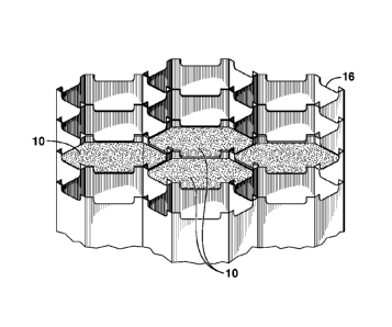
[0020] Figure 7 hereof is a partial side cross-sectional view of the top
section of a
plurality of monolith liners of the present invention secured together and
showing the
placement of a bonding agent, weld, and paraffin pad used during the bonding
step.
[0021] Figure 8 hereof is an enlarged top section of a monolith contactor
assembly of the
present invention showing boding agent between the monolith and liner.
[0022] Figure 9 hereof is a side cross-sectional view of a swing adsorption
reaction vessel
containing an assembly of lined monolith contactors and how they are secured
to the interior
of the vessel.
[0023] Figure 10 hereof is a cross-sectional view along the vertical axis
of a cylindrical
swing adsorption vessel containing an assembly of encased monolith adsorbent
contactors of
the present invention.
[0024] Figures 11A through 11F are cross-sectional views along a
horizontal plane of a
swing adsorption vessel containing monolith assemblies that have a variety of
non-limiting
examples of geometric shapes for the monoliths and monolith liners according
to different
embodiments of the present invention. Figure 12 is an illustration of an
elevation view of an
exemplary hydrocarbon treating apparatus comprised of a swing adsorption
system with 14
adsorbent bed assemblies arranged in two levels of seven beds equally spaced
around the
central valve and flow distribution assembly.
[0025] Figure 13 is an illustration of a plan view of an exemplary
hydrocarbon treating
apparatus comprised of a swing adsorption system with 14 adsorbent bed
assemblies arranged
in two levels of seven beds equally spaced around the central valve and flow
distribution
assembly.
[0026] Figure 14 is a three-dimensional diagram of another exemplary
hydrocarbon
treating apparatus comprised of a swing adsorption system with seven adsorbent
bed
assemblies arranged in two rows.
4
CA 02824986 2016-12-23
[0027] Figures 15A, 15B, and 15C are top, side, and bottom views,
respectively, of an
individual adsorbent bed assembly from the exemplary hydrocarbon treating
apparatus in
Figure 14.
[0028] Figure 16 is a three-dimensional diagram of individual adsorbent
bed support
structures attached to the skid base for the exemplary hydrocarbon treating
apparatus of
Figure 14.
[0029] Figures 17A, 17B, and 17C are top, side, and bottom views,
respectively, of a pair
of individual adsorbent bed assemblies with interconnecting piping and bed
support
structures for the exemplary hydrocarbon treating apparatus in Figure 14.
[0030] Figure 18 is a three-dimensional diagram of the valves and piping
network for the
seven interconnected adsorbent beds of the exemplary hydrocarbon treating
apparatus of
Figure 14.
DETAILED DESCRIPTION OF THE INVENTION
[0031] Unless otherwise explained, all technical and scientific terms
used herein have the
same meaning as commonly understood by one of ordinary skill in the art to
which this
disclosure pertains. The singular terms "a," "an," and "the" include plural
referents unless the
context clearly indicates otherwise. Similarly, the word "or" is intended to
include "and"
unless the context clearly indicates otherwise. The term "includes" means
"comprises."
Directional terms, such as "upper," "lower," "top," "bottom," "front," "back,"
"vertical," and
"horizontal," are used herein to express and clarify the relationship between
various elements.
It should be understood that such terms do not denote absolute orientation
(e.g., a "vertical"
component can become horizontal by rotating the device). The materials,
methods, and
examples recited herein are illustrative only and not intended to be limiting.
[0032] Monolith adsorbent contactors are defined herein is a subset of
adsorbent
contactors comprising structured (engineered) adsorbents in which
substantially parallel flow
channels are incorporated into the adsorbent structure. These flow channels
may be formed
by a variety of means, including extruded ceramic monoliths, bundles of hollow
fibers, spiral
wound adsorbent layers, stacked layers of adsorbent sheets with and without
spacers, and
other methods. In addition to the adsorbent material, the structure may
contain items such as,
5
CA 02824986 2016-10-21
but not limited to, support materials, heat sink materials, void reduction
components, and
other materials.
Exemplary contactors are described in U.S. Patent App. Pub. No.
2008/0282892.
[0033]
This invention relates to an enhanced swing adsorption contactor system. This
system includes monolith adsorbent contactor liners and the installation of a
plurality of the
liners into a cylindrical vessel or an irregular shaped containment boundary,
preferably a
swing adsorption vessel. There are several benefits of the present invention
over the prior art.
For example, the swing adsorption vessels can be optimized overall by limiting
the cross
sectional area of non-process material. The present invention also provides a
means of
achieving both accurate and repeatable fabrication and installation results.
Further, the
internal mechanical support and hold-down structures for an assembly of lined
monolith
contactors of the present invention are also simplified. The undesirable stray
gaseous stream
paths between contactors of conventional assemblies are substantially
eliminated. Another
benefit of the present invention over the prior art is providing a cost
effective robust means of
anchoring the monolith contactors in a gaseous process environment. Still
another benefit of
the present invention is providing a direct scale-up relationship between a
smaller
demonstration unit and the full size commercial unit. An individual adsorbent
monolith
having a metallic liner can be equal in size for both given applications.
[0034]
The lined monolith adsorbent contactors of the present invention can also be
constructed to accommodate numerous geometric shapes without the need of
relying on
specialized fabrication tools, assembly techniques or industry know-how. The
contactor
liners of the present invention can be made from any suitable material that is
able to
withstand the operating conditions and environment of their intended use,
preferably swing
adsorption conditions. Such conditions include temperatures up to 100 C and
pressures up
to 1200 pounds per square inch absolute (psia) (8274 kilo Pascal absolute
(kPaa)). Stainless
steels are the most preferred materials for use as liners of the present
invention. The wall
thickness of the liners of the present invention may be from about 3/32 to
3/16 inch (in)
(0.02381 to 0.004762 meters (m)), preferably from 1/8 to 'A in (0.003175 to
0.000625 m), and
more preferably from 1/16 to 1/8 in (0.001587 to 0.003175 m). The liners of
the present
invention can be brake-bent from flat plate or can begin with commercially
available shaped
pipe with post fabrication steps.
[0035] This invention can be better understood with reference to the
figures hereof.
Figures IA and 1B illustrate conventional practice for stacking a plurality of
catalyst
6
CA 02824986 2013 07 16
WO 2012/118755 PCT/US2012/026797
2011EM065-PCT
substrates or monolith adsorbent contactors in a pressure vessel 11. Figure lA
shows a top
cross-sectional view showing contactors 10 for this arrangement in the vessel
11. Figure 1B
is an enlarged view of a section 1B of the plurality of the contactors and
shows how an
undesirable gaseous path 12 can form in the space between contactors. The term
"space"
means a region or volume, which may be bounded by one or more objects. In this
manner, a
portion of the gas stream may bypass the contactors or desired process area
within the
contactors. This undesired path degrades the performance or efficiency of the
system and
operation of a process (e.g., lessen purity of the respective streams in the
process). Figure
2A hereof is a cross-sectional view along the vertical axis of a typical
pressure vessel 11
containing an assembly of stacked monolith adsorbent contactors 10. Also shown
are
mechanical hold-down and support structures 14. Figure 2B is an enlarged view
of a section
2B of the assembly of contactors showing an undesirable gaseous path 12
between contactors
that is a potential defect in conventional monolith adsorbent contactor
assemblies. Even if
the individual monolith adsorbent contactors are bonded together with glue or
cement, it is
difficult to verify the effectiveness of the bond and determine whether all
the undesirable gas
flow paths have been eliminated. Furthermore, the mechanical hold-down and
support
structures 14 transmit forces directly to the faces of the individual monolith
adsorbent
contactors, which in many cases do not have the mechanical integrity to
withstand the forces
encountered during rapid cycle swing adsorption processes.
[0036] Figures 3 and 4 hereof show a hollow rigid liner, which may include
as a non-
limiting example a metallic liner 16, in the shape of a hexagonal tube. Liner
16 wraps the
external non-process surface of each individual monolith adsorbent contactor
with a thin
metallic skin, which provides a substantially uniform annular space between
the inner surface
of the metallic liner 16 and the monolith adsorbent contactor for a monolithic
anchoring
system. The extreme ends of the metallic liner have integrated stand-offs 18
that project in
the axial direction as better shown in the enlarged view of Figures 4 and 7.
These formed
ends or stand-offs 18 provide a consistent means of spacing the monolith's
process face from
the pressure vessels inner horizontal surfaces. The benefit of the metallic
liner 16 and
standoffs 18 is that forces are distributed to the large external non-process
surface of each
individual monolith adsorbent contactor, rather than the inlet and outlet
faces containing the
gas flow channels as in the prior art. Accordingly, the adsorbent contactor
assembly is much
more capable of withstanding the large forces applied to the adsorbent
contactor assembly
during rapid cycle swing adsorption processes. A further benefit is that the
formed ends also
7
CA 02824986 2013 07 16
WO 2012/118755 PCT/US2012/026797
2011EM065-PCT
provide a uniform means of cross sharing or distributing the gaseous process
streams between
all monoliths.
[0037] The individual metallic liners can be deployed into an assembly
fixture jig (not
shown), which represents the inside geometry of the intended pressure boundary
(e.g., which
may be similar to the pressure vessel 11). The design shown in these figures
(see Figures 4,
5B and 7, for example) offers a substantially uniform location between all
adjacent liners,
which are fixedly connected to each other for a robust seal. As a non-limiting
example of
being fixedly connected, a seal weld 20 is located between all adjacent stand-
offs 18. The
weld 20 has a dual purpose of securing each independent metallic liner 16 to
one another, in
addition to providing a reliable seal weld that substantially eliminates
gaseous stream paths
between liners. The weld seam can be bonded by techniques known in the art.
Non-limiting
examples of techniques suitable for fixedly connecting include bonding the
welds of the
present invention via gluing, brazing and tinning. A separate multi-sided
channel material
can also be added with a bonding technique over the resulting butt seam (not
shown) that
joins each adjacent liner. Figure 4 hereof shows an assembly of four metallic
liners of the
present invention and the location of the seal weld 20 between stand-offs 18.
Figure 7 shows
an enlarged view of the seal weld 20 between adjacent stand-offs 18.
[0038] Figure 5A hereof shows a stack 22 of three monolith adsorbent
contactors 10,
which are held together by preferably, but not limited to, a tape 24,
preferably a tape
comprised of a metal foil at each face-to-face junction. The tape ensures that
the channels
along the fact-to-face junction do not become plugged or blocked during the
gluing step. Foil
coated tape is preferred because it provides additional protection since it
most likely does not
adsorb the glue, or bonding agent. Any number of monolith contactors can be
stacked
together depending on the height of the liner 16 for the intended adsorbent
bed height. The
monolith assembly begins with a plurality of monolith contactors, stacked to a
desired
vertical depth and having foil tape at each face-to-face junction. Figure 5B
hereof is a top
perspective view of a liner/monolith contactor assembly before any of the
stacked monolith
adsorbent contactors 10 are placed therein. As shown in Figure 5B, each liner
of the plurality
of hollow rigid liners 16 has an inner surface that defines an interior
region, a first open axial
end along a longitudinal axis, a second open axial end along the longitudinal
axis opposite the
first open axial end, and an outer surface external to the interior region.
Also, as shown in
Figure 5A, each of the monolith adsorbent contactors 10 have a body that
defines at least one
passage through the body along the longitudinal axis and an outer surface of
the body.
8
CA 02824986 2013 07 16
WO 2012/118755 PCT/US2012/026797
2011EM065-PCT
[0039] Figure 6 shows a top perspective view of a liner/monolith
contactor assembly with
four of the stacked monolith contactors placed therein. It is noted that
liners 16 and monolith
adsorbent contactors 10 are manufactured so that a number of monoliths fit
inside of each
liner so that only the stand-offs 18 at each end of the liner extend past the
face of the
monolith contactor. As shown in Figure 6, four of the plurality of liners 16
have a monolith
adsorbent contactor disposed within the respective liners. A bonding agent
(not shown) is
disposed between the outer surface of the respective monolith adsorbent
contactor and the
respective inner surface of the liner to hinder gaseous flow between the
monolith adsorbent
contactor and the hollow rigid liner.
[0040] Figure 7 hereof is a partial side cross-sectional view of a top
section of a monolith
contactor assembly of the present invention. The monolith adsorbent contactor
10 in the
overall assembly is preferably concentrically positioned within the formed
metallic liner 16.
This geometry provides a uniform annular gap for a monolithic anchoring
system. The
exposed process face of each monolith is coated with a layer 27 of low melting
material,
preferably a paraffinic material to protect the monolith contactor process
areas when a
viscous bonding agent 28 is poured into the annular space and which is
ultimately cured to
form a semi-rigid but flexible anchoring system for the overall assembly.
[0041] Figure 8 hereof shows an enlarged top section of a monolith
contactor assembly of
the present invention showing bonding agent 28 between the monolith adsorbent
contactor 10
and liner 16. The combination of the seal weld seam 20 and semi-rigid
anchoring system
mitigates all or substantially reduces unwanted and undesirable gaseous stream
paths. A
further advantage of this embodiment is the ability to test each liner and
monolith assembly
for pressure integrity to ensure that the bonding agent has fully sealed the
annular gap
between the liner and the monolith adsorbent contactor. While the layer of low
melting
material is still present to block the gas flow channels within the monolith
adsorbent
contactor, the liner and monolith adsorbent contactor assembly can be pressure
tested to
ensure that each liner assembly is properly constructed. This capability is
not provided in
conventional assemblies of monolith adsorbent contactors.
[0042] The bonding agent may be a polymer-based composition, e.g.,
thermoplastic and
thermosets, adhesive compositions, such as contact adhesives or hot melt
adhesives, rubber,
i.e., natural or synthetic, elastomers, or combination thereof Also, the
bonding agent may
include a heavy petroleum wax (e.g. Apiezon), bitumen, asphalt, etc. and the
like.
9
CA 02824986 2013 07 16
WO 2012/118755 PCT/US2012/026797
2011EM065-PCT
[0043] Once the assembly is removed from the fixture jig, it can be
concentrically
positioned in the pressure vessel. The annular gap between the pressure vessel
inside surface
and the assembly outermost material can be filled in a similar manner with a
viscous bonding
agent, as one example. The dispensable paraffin can be melted and drained from
the pressure
vessel to expose the axial ends of the monolith adsorbent contactor 10 in the
assembly. The
resulting exemplary monolith contactor assembly is shown in Figure 9 hereof
positioned
within a swing adsorption vessel 31. Figure 9 also shows a soft paraffinic
ring 30 installed at
the bottom of the vessel onto which the monolith assembly is lowered. This
paraffinic ring
30 is provided to deform under the weight of the monolith assembly and
provides a
temporary seal which prevents the bonding agent 28 from traveling beyond its
intended
annular space. After the bonding agent has been positioned in the annular
space, the
paraffinic ring 30 can be melted and drained from the vessel. The term
"paraffinic" as used
herein means any suitable waxy material, both natural and synthetic. Natural
waxes are
waxes derived from animal, insect, mineral/petroleum, and vegetable sources.
Non-limiting
examples of waxes that are suitable for being recovered in the process of the
present
invention include: insect and animal waxes, preferably beeswax, Chinese insect
wax, wool
wax, and spermaceti; vegetable waxes, such as candelilla, carnauba,
candelilla, Japan wax,
ouricury wax, rice-bran wax, jocoba, castor wax, and bayberry wax; mineral
waxes, such as
montan wax, peat wax, ozokerite and ceresin waxes; petroleum waxes, such as
paraffin and
microcrystalline waxes; and synthetic waxes, such as polyethylene waxes, and
mixtures
thereof It is also within the scope of this invention that the spacing can be
provided by the
use of physical protrusions (not shown) instead of the use of a wax. Crystals
of a suitable
material like tublimate could also be used to form the space, then dissolved
away to leave the
desired space. In addition, other materials may be utilized that can be easily
burned or
oxidized away, such as paper or cellulose, or even low temperature melting
metals, such as
tin, Wood's metal, or Field's metal. Similarly, low temperature melting metals
can be used
as the sealing agent instead of organic materials.
[0044] Figure 10 hereof is a cross-sectional view along the vertical
axis of a cylindrical
swing adsorption vessel containing an assembly of encased monolith adsorbent
contactors 10
of the present invention. This figure shows the mechanical hold-down and
support structure,
such as stand-offs 18, which is an integral part of the monolith liners. As
discussed
previously, this integral support structure provides uniform distribution of
forces to secure the
assembly of monolith adsorbent contactors to the pressure vessel with maximum
structural
CA 02824986 2013 07 16
WO 2012/118755 PCT/US2012/026797
2011EM065-PCT
integrity. Additionally, the flow passages formed between the standoffs 18 and
the vessel 31
create the means for uniform flow distribution to the assembly of monolith
adsorbent
contactors.
[0045] Figures 11A through 11F show cross-sectional views along a
horizontal plane of a
swing adsorption vessel containing monolith assemblies have a variety of non-
limiting
examples of geometric shapes 32A-32H that the monoliths and monolith liners of
the present
invention can take. The individually lined monolith can be formed to any
geometric shape,
which ideally fits into a specified pressure vessel boundary. For example,
Figure 11A
includes various hexagonal shaped hollow-rigid liners and contactors, while
Figure 11B
includes various square shaped hollow-rigid liners and contactors. Figure 11D
includes
various triangular shaped hollow-rigid liners and contactors, while Figure 11F
includes
various rectangular shaped hollow-rigid liners and contactors. Further, a
uniform shape can
be deployed or a combination of geometric shapes can be mixed to form the
overall monolith
process area. As exemplary embodiments, Figure 11A, 11B, 11D and 11F have
liners having
substantially uniform geometric shapes, while Figures 11C and 11E have liners
of different
geometric sizes and/or shapes. Specifically, Figure 11C includes various
circular shaped
hollow-rigid liners and contactors of different diameters, while Figure 11E
includes various
square shaped hollow-rigid liners and contactors and various hexagonal shaped
hollow-rigid
liners and contactors, which have different cross sectional areas. As may be
appreciated,
different geometric shapes may be utilized for different embodiments. For
instance, the
configuration may be utilized to maximize the process area for streams flowing
through the
vessel.
[0046] The provided adsorbent contactors are useful in adsorptive kinetic
separation
processes, apparatus, and systems for development and production of
hydrocarbons, such as
gas and oil processing. Particularly, the provided processes, apparatus, and
systems are
useful for the rapid, large scale, efficient separation of a variety of target
gases from gas
mixtures.
[0047] The provided adsorbent contactors described above are useful in
swing adsorption
processes. Non-limiting swing adsorption processes include pressure swing
adsorption
(PSA), vacuum pressure swing adsorption (VPSA), temperature swing adsorption
(TSA),
partial pressure swing adsorption (PPSA), rapid cycle pressure swing
adsorption (RCPSA),
rapid cycle thermal swing adsorption (RCTSA), rapid cycle partial pressure
swing adsorption
11
CA 02824986 2013 07 16
WO 2012/118755 PCT/US2012/026797
2011EM065-PCT
(RCPPSA), as well as combinations of these processes such as pressure/
temperature swing
adsorption.
[0048] PSA processes rely on the phenomenon of gases being more readily
adsorbed
within the pore structure or free volume of an adsorbent material when the gas
is under
pressure, i.e., the higher the gas pressure, the greater the amount readily-
adsorbed gas
adsorbed. When the pressure is reduced, the adsorbed component is released, or
desorbed.
[0049] PSA processes may be used to separate gases of a gas mixture
because different
gases tend to fill the micropore of the adsorbent to different extents. If a
gas mixture, such as
natural gas, is passed under pressure through a vessel containing a polymeric
or microporous
adsorbent that is more selective towards carbon dioxide than it is for
methane, at least a
portion of the carbon dioxide may be selectively adsorbed by the adsorbent,
and the gas
exiting the vessel may be enriched in methane. When the adsorbent reaches the
end of its
capacity to adsorb carbon dioxide, it is regenerated by reducing the pressure,
thereby
releasing the adsorbed carbon dioxide. The adsorbent is then typically purged
and
repressurized and ready for another adsorption cycle.
[0050] TSA processes rely on the phenomenon that gases at lower
temperatures are more
readily adsorbed within the pore structure or free volume of an adsorbent
material compared
to higher temperatures, i.e., when the temperature of the adsorbent is
increased, the adsorbed
gas is released, or desorbed. By cyclically swinging the temperature of an
adsorbent bed,
TSA processes can be used to separate gases in a mixture when used with an
adsorbent that is
selective for one or more of the components of a gas mixture.
[0051] Swing adsorption processes typically take place in a vessel
containing one or more
adsorbent beds. In multi-bed systems each bed may undergo a different step in
an adsorption
cycle, such as an adsorption step, one or more depressurization/desorption
steps, one or more
blow-down steps, and one or more repressurization steps. The flow of fluid to
and from each
bed is typically controlled by a valve, such as a poppet valve and/or a rotary
valve assembly.
[0052] The provided processes, apparatus, and systems may be used to
prepare natural
gas products by removing contaminants and heavy hydrocarbons, i.e.,
hydrocarbons having at
least two carbon atoms. The provided processes, apparatus, and systems are
useful for
preparing gaseous feed streams for use in utilities, including separation
applications such as
dew point control, sweetening/detoxification, corrosion protection/control,
dehydration,
heating value, conditioning, and purification. Examples of utilities that
utilize one or more
12
CA 02824986 2013 07 16
WO 2012/118755 PCT/US2012/026797
2011EM065-PCT
separation applications include generation of fuel gas, seal gas, non-potable
water, blanket
gas, instrument and control gas, refrigerant, inert gas, and hydrocarbon
recovery. Exemplary
"not to exceed" product (or "target") gas specifications include: (a) 2 vol.%
CO2, 4 ppm H2S,
(b) 50 ppm CO2, 4 ppm H2S, or (c) 1.5 vol.% CO2, 2 ppm H2S.
[0053] The provided processes, apparatus, and systems may be used to remove
acid gas
from hydrocarbon streams. Acid gas removal technology becomes increasingly
beneficial as
remaining gas reserves exhibit higher concentrations of acid gas, e.g., sour
gas resources.
Hydrocarbon feed streams vary widely in amount of acid gas, such as from
several parts per
million acid gas to 90 vol.% acid gas. Non-limiting examples of acid gas
concentrations in
natural gas from exemplary gas reserves include concentrations of at least:
(a) 1 vol.% H2S,
5 vol.% CO2, (b) 1 vol.% H2S, 15 vol.% CO2, (c) 1 vol.% H2S, 60 vol.% CO2, (d)
15 vol.%
H2S, 15 vol.% CO2, and (e) 15 vol.% H2S, 30 vol.% CO2. For these streams, the
hydrocarbons may include remaining portions of the total volume of the stream.
[0054] An exemplary hydrocarbon treating apparatus is shown in Figures 12
and 13.
Figure 12 is a top view of the swing adsorption system 1200, while Figure 13
is a partial side
view of the swing adsorption system 1300 with certain adsorbent bed assemblies
omitted for
simplicity. This apparatus is a compact swing adsorption system 1200 with
fourteen
adsorbent bed assemblies. The fourteen adsorbent bed assemblies are stacked
two layers with
the top adsorbent bed assemblies 1201-1207 being illustrated in Figure 12. A
rotary valve
assembly 1208 is concentrically located in a cylindrical housing with a rotary
valve, which is
positioned equidistant to the enjoined adsorbent bed assemblies. The
cylindrical housing
further acts as a means of supporting a plurality of such adsorbent bed
assemblies, conduits
and valves in a multi-tier level arrangement. Gaseous streams are transferred
through a given
adsorbent bed by way of both the central rotary valve and one or more
reciprocating valves
located on the vessel heads. The gaseous stream has bi-directional travel
between the ports of
either of the reciprocating or rotary valves through a fixed conduit. The
transfer duration of
subsequent gaseous streams is limited and directed by the predetermined
adsorption cycle.
[0055] Another feature of the apparatus shown in Figures 12 and 13
relates to a method
of coordinating the activation mechanism of the reciprocating valve to either
open or close at
several predetermined physical locations on the rotary valve itself In the
present
embodiment, a reliable and repeatable means of replicating precise operable
coordination
between the open or closed ports of the respective valves is provided for the
adsorption cycle.
This embodiment uses a traveling magnet assigned as a transmitter location,
which is aligned
13
CA 02824986 2016-12-23
to a fixed magnetic assigned as a receiving location. A generated flux signal
between the
magnets activates a specified mechanized driver of a given reciprocating valve
for a specified
duration. The art of generating and reading the change in a magnetic flux
signal is
scientifically recognized as the Hall Effect. The hydrocarbon treating
apparatus shown in
Figures 12 and 13 can be implemented in many different configurations.
[0056] One possible alternative embodiment is shown in Figures 14, 15A,
15B, 15C, 16,
17A, 17B and 17C. In this embodiment, the fourteen individual adsorbent bed
assemblies
may be arranged in two skids, each of the skids containing seven of the
individual adsorbent
bed assemblies arranged in two rows. One of the exemplary skids is shown in
Figure 14.
Multiple reciprocating (or poppet) valves are arranged on the top and bottom
of each vessel
and connected via piping and headers above and below the adsorbent bed
assemblies.
[0057] An individual adsorbent bed assembly is shown in Figures 15A-15C.
As shown in
the side view of Figure 15B, various feed piping may pass the gaseous feed
stream to the
adsorbent bed assembly 1502 and the product stream may be removed via the
bottom piping.
The feed gas enters and exhaust gas exits through the piping and valves on the
top of the
vessel as shown in the top view of Figure 15A. Product gas exits the adsorbent
vessel
through one of the valves and piping systems on the bottom of the vessel as
shown in the
bottom view in Figure 15C. Other equalization and purge valves and piping are
also included
in Figures 15A-15C.
[0058] Each adsorbent bed assembly can be first fitted with the requisite
reciprocating
valves and then placed in the bed support structure 1601-1607 mounted on the
skid 1610,
which is shown in Figure 16 as 1600. Once the seven adsorbent bed assemblies
are set in
their respective support structure 1601-1607, the bed assemblies can be
interconnected via
piping and headers. The bed support structures 1601-1607 may be configured to
permit
movement to allow for thermal expansion or contraction of the piping system
associated with
the bed assembly. While the individual bed support structures 1601-1607 are
fixed to the
skid base 1610, the adsorbent bed assemblies, which are noted in other
figures, may be
disposed into the bed support structure 1601-1607 without being rigidly
attached or securely
fixed. Therefore, the entire adsorbent bed assembly can move freely within the
bed support
structure to accommodate thermal expansion or contraction of the piping and
minimize
stresses on the piping and valves.
14
CA 02824986 2016-12-23
[0059]
Figures 17A-17C provides different views of two bed assemblies. For instance,
a
top view of two interconnected beds is shown in Figure 17A, a bottom view of
two
interconnected bed assemblies is shown in Figure 17C, and a side view of the
interconnected
bed assemblies in the support structure is shown in Figure 17B.
[0060] The piping, valves, and headers for a complete skid as connected are
shown in
Figure 18 without the adsorbent bed assemblies or support structure to
illustrate the piping
network. The top piping and headers are shown relative to the bottom piping
and headers in
this embodiment. The piping can be designed to be self-supporting, or
additional structure
can be provided to support the piping network within the skid.
[0061] One or more of the following Concepts A-0 may be utilized with the
processes,
apparatus, and systems, provided above, to prepare a desirable product stream
while
maintaining high hydrocarbon recovery:
Concept A: using one or more kinetic swing adsorption process, such as
pressure swing
adsorption (PSA), thermal swing adsorption (TSA), calcination, and partial
pressure
swing or displacement purge adsorption (PPSA), including combinations of these
processes; each swing adsorption process may be utilized with rapid cycles,
such as
using one or more rapid cycle pressure swing adsorption (RC-PSA) units, with
one or
more rapid cycle temperature swing adsorption (RC-TSA) units or with one or
more
rapid cycle partial pressure swing adsorption (RC-PPSA) units; exemplary
kinetic swing
adsorption processes are described in U.S. Patent Application Publication Nos.
2008/0282892, 2008/0282887, 2008/0282886, 2008/0282885, and 2008/0282884;
Concept B: removing acid gas with RC-TSA using advanced cycles and purges as
described in U.S. patent application no. 61/447848, filed March 1,2011;
Concept C: using a mesopore filler to reduce the amount of trapped
methane in the adsorbent and increase the overall hydrocarbon recovery, as
described in U.S. Patent Application Publication Nos. 2008/0282892,
2008/0282885, 2008/028286. The non-sweepable void space present
within the adsorbent channel wall is can be defined by the total volume
occupied by
mesopores and macropores. Mesopores are defined by the IUPAC to be pores
15
CA 02824986 2016-10-21
, .
with sizes in the 20 to 500 angstrom size range. Macropores are defined herein
to be
pores with sizes greater than 500 angstrom and less than 1 micron. Because the
flow
channels are larger than 1 micron in size, they are not considered to be part
of the
macropore volume. The non-sweepable void space is defined herein as the open
pore
volume occupied by pores in the absorbent that are between 20 angstroms and
10,000
angstroms (1 micron) in diameter divided by the total volume of the contactor
that is
occupied by the absorbent material including associated mesopores and
macropores in
the absorbent structure. The non-sweepable void space, hereafter referred to
collectively
as mesopores, can be reduced by filling the mesopores between the particles to
reduce
the open volume while allowing rapid gas transport throughout the adsorbent
layer. This
filling of the non-sweepable void space is desired to reduce to acceptable
levels the
quantity of desired product lost during the rapid desorption step as well as
to allow a
high degree of adsorbent bed purity following desorption. Such mesopore
filling can be
accomplished in a variety of ways. For example, a polymer filler can be used
with rapid
diffusion of H2S and CO2, such as a silicon rubber or a polymer with intrinsic
porosity.
Alternatively, a pyrolitic carbon having mesoporosity and/or microporosity
could be
used to fill the void space. Still another way is by filling the void space
with inert solids
of smaller sizes, or by filling the void space with a replenishable liquid
through which
the desired gases rapidly diffuse (such as water, solvents, or oil).
Preferably, the void
space within the adsorbent wall is reduced to less than about 40 volume
percent (vol.%),
preferably to less than 30 vol.%, and more preferably to less than 20 vol.%,
and even more
preferably to less than 10 vol.% and most preferably less than about 5 vol% of
the open pore
volume;
Concept D: choosing an appropriate adsorbent materials to provide high
selectivity and
minimize adsorption (and losses) of methane and other hydrocarbons, such as
one or more of
the zeolites described in U.S. Patent Application Publication Nos.
2008/0282887 and
2009/0211441.
Preferred adsorbents for the removal of acid gases are selected
from a group consisting of mesoporous
or m icroporous materials,
with or without functionality for chemical reactions with acid gases. Examples
of materials
without functionality include cationic zeolites and stannosilicates.
Functionalized materials
that chemically react with H2S and CO, exhibit significantly increased
selectivity for H2S
and CO, over hydrocarbons. Furthermore, they do not catalyze undesirable
reactions with
hydrocarbons that would occur on acidic zeolites.
Functionalized mesoporous
16
CA 02824986 2013 07 16
WO 2012/118755 PCT/US2012/026797
2011EM065-PCT
adsorbents are also preferred, wherein their affinity toward hydrocarbons is
further
reduced compared to un-functionalized smaller pore materials, such as
zeolites.
Alternatively, adsorption of heavy hydrocarbons can be kinetically suppressed
by
using small-pore functionalized materials, in which diffusion of heavy
hydrocarbons is
slow compared to H2S and CO2. Care should also be taken to reduce condensation
of
hydrocarbons with carbon contents equal to or above about 4 (i.e., C4+
hydrocarbons) on
external surfaces of H2S and CO2 selective adsorbents.
Non-limiting example of functional groups suitable for use herein include
primary, secondary, tertiary and other non-protogenic, basic groups such as
amidines,
guanidines and biguanides. Furthermore, these materials can be functionalized
with two
or more types of functional groups. To obtain substantially complete removal
of H2S
and CO2 from natural gas streams, an adsorbent material preferably is
selective for H2S
and CO2 but has a low capacity for both methane and heavier hydrocarbons
(C2+). In
one or more embodiments, it is preferred to use amines, supported on silica
based or
other supports because they have strong adsorption isotherms for acid gas
species. They
also have high capacities for such species, and as a consequence of their high
heats of
adsorption, they have a relatively strong temperature response (i.e. when
sufficiently
heated they readily desorb H2S and CO2 and can thus be used without excessive
temperature swings). Preferred are adsorbents that adsorb in the 25 C to 70
C range
and desorb in the 90 C to 140 C range. In systems requiring different
adsorbents for
CO2 and H2S removal, a layered bed comprising a suitable adsorbent for the
targeted
species may be desirable.
For CO2 removal from natural gas, it is preferred to formulate the adsorbent
with a
specific class of 8-ring zeolite materials that has a kinetic selectivity. The
kinetic
selectivity of this class of 8-ring zeolite materials allows CO2 to be rapidly
transmitted
into zeolite crystals while hindering the transport of methane so that it is
possible to
selectively separate CO2 from a mixture of CO2 and methane. For the removal of
CO2
from natural gas, this specific class of 8-ring zeolite materials preferably
has a Si/A1 ratio
from about 1 to about 25. In other preferred embodiments, the Si/A1 ratio of
the zeolite
material is from 2 to about 1000, preferably from about 10 to about 500, and
more
preferably from about 50 to about 300. It should be noted that as used herein,
the term
Si/A1 is defined as the molar ratio of silica to alumina of the zeolitic
structure. This
preferred class of 8-ring zeolites that are suitable for use herein allow CO2
to access the
17
CA 02824986 2013 07 16
WO 2012/118755 PCT/US2012/026797
2011EM065-PCT
internal pore structure through 8-ring windows in a manner such that the ratio
of single
component diffusion coefficients for CO2 over methane (i.e., DCO2/DCH4) is
greater
than 10, preferably greater than about 50, and more preferably greater than
about 100
and even more preferably greater than 200.
In many instances, nitrogen also has to be removed from natural gas or gas
associated with the production of oil to obtain high recovery of a purified
methane
product from nitrogen containing gas. There have been very few molecular sieve
sorbents with significant equilibrium or kinetic selectivity for nitrogen
separation from
methane. For N2 separation from natural gas it is also preferred to formulate
the
adsorbent with a class of 8-ring zeolite materials that has a kinetic
selectivity. The
kinetic selectivity of this class of 8-ring materials allows N2 to be rapidly
transmitted
into zeolite crystals while hindering the transport of methane so that it is
possible to
selectively separate N2 from a mixture of N2 and methane. For the removal of
N2, from
natural gas, this specific class of 8-ring zeolite materials also has a Si/A1
ratio from about
2 to about 1000, preferably from about 10 to about 500, and more preferably
from about
50 to about 300. This preferred class of 8-ring zeolites that are suitable for
use herein
allow N2 to access the internal pore structure through 8-ring windows in a
manner such
that the ratio of single component diffusion coefficients for N2 over methane
(i.e.,
DN2/DCH4) is greater than 5, preferably greater than about 20, and more
preferably
greater than about 50 and even more preferably greater than 100. Resistance to
fouling
in swing adsorption processes during the removal N2 from natural gas is
another
advantage offered by this class of 8-ring zeolite materials.
In a preferred embodiment, H25 is selectively removed with a non-aqueous
sorbent comprising a basic non-protogenic nitrogenous compound supported on a
marcroporous, mesoporous, or microporous solid. The non-protogenic nitrogenous
compound selectively reacts with at least a portion of the H25 in the feed gas
mixture.
Examples of suitable porous solid supports include activated charcoal or solid
oxides
(including mixed oxides), such as alumina, silica, silica-alumina or acidic or
non-acidic
zeolites. The basic non-protogenic nitrogenous compound may simply be
physically
sorbed on the support material (e.g. by impregnation or bonded with or grafted
onto it by
chemical reaction with the base itself or a precursor or derivative in which a
substituent
group provides the site for reaction with the support material in order to
anchor the
sorbent species onto the support). Bonding is not, however, required for an
effective
18
CA 02824986 2013 07 16
WO 2012/118755 PCT/US2012/026797
2011EM065-PCT
solid phase sorbent material. Support materials which contain reactive surface
groups,
such as the silanol groups found on zeolites and the M41S silica oxides are
capable of
reacting with siloxane groups in compounds, such as
trimethoxysilylpropyldimethylamine. Non-protogenic nitrogenous compounds do
not
enter into chemisorption reactions with CO2 in the absence of water although
they do
undergo reaction with H2S. This differential chemical reactivity is used to
make the
separation between the H25 and the CO2. A wide variety of basic nitrogen-
containing
compounds may be used as the essential sorbent. If desired, a combination of
such
compounds may be used. The requirement for the desired selectivity for H25
adsorption
is that the nitrogenous groups be non-protogenic, that is, incapable of acting
as a proton
donor. The nitrogenous groups therefore do not contain an acidic, dissociable
hydrogen
atom, such as nitrogen in a primary or secondary amine. It is not required
that the whole
compound be aprotic, only that the nitrogen-containing groups in the compound
be non-
protogenic. Non-protogenic nitrogen species cannot donate an H+ (proton),
which is a
prerequisite for the formation of carbamates as a route for the CO2
chemisorption
reaction in the absence of water; they are non-nucleophilic under the
prevailing reaction
conditions. Suitable nitrogenous compounds include tertiary amines such as
triethylamine, triethanolamine (TEA), methyldiethanolamine (MDEA), N-methyl
diethanolamine (CH3N(C2H4OH)2), ¨
tetrakis (2 - hydroxyethyl)
ethylenediamine as well as non-protogenic nitrogenous bases with cyclic,
multicyclic,
and acyclic structures, such as imines, heterocyclic imines and amines,
amidines
(carboxamidines) such as dimethylamidine, guanidines, triazabicyclodecenes,
imidazolines, and pyrimidines. Compounds such as the N,N-di(lower alkyl)
carboxamidines where lower alkyl is preferably C1-C6 alkyl, N-
methyltetrahydropyrimidine (MTHP), 1,8-diazabicyclo[5.4.0]-undece-7-ene (DBU),
1,5,7-triazabicyclo[4.4.0]dec-5-ene (TBD), 7-methyl-1,5,7-
triazabicyclo[4.4.0]dec-5-ene
(MTBD), 1,5-diazabicyclo[4.3.0]non-5-ene (DBN), substituted guanidines of the
formula (R1R2N)(R3R4N)C=N-R5 where R1, R2, R3 and R4 are preferably lower
alkyl
(C1-C6) and R5 is preferably H or lower alkyl (C1-C6), such as 1,1,3,3-
tetramethylguanidine and biguanide, may also be used. Other substituent groups
on
these compounds such as higher alkyl, cycloalkyl, aryl, alkenyl, and
substituted alkyl
and other structures may also be used.
19
CA 02824986 2013 07 16
WO 2012/118755 PCT/US2012/026797
2011EM065-PCT
Another class of materials that is capable of removing H2S and CO2, from
natural
gas streams is cationic zeolites. Selectivity of these materials for H25 and
CO2 depends
on the framework structure, choice of cation, and the Si/A1 ratio. In a
preferred
embodiment the Si/A1 ratio for cationic materials is in a range from 1 to 50
and more
preferably a range from 1 to 10. Examples of cationic zeolite include
zeolites, 4A, 5A
and faujasites (Y and X). It is preferred to use these materials for
selectively removing
H25 and CO2 after the feed stream has been dehydrated.
Other non-limiting examples of preferred selective adsorbent materials for use
in
embodiments herein include microporous materials such as zeolites, A1P0s,
SAPOs,
MOFs (metal organic frameworks), ZIFs (zeolitic imidazolate frameworks, such
as ZIF-
7, ZIF-8, ZIF-22, etc.) and carbons, as well as mesoporous materials such as
the amine
functionalized MCM materials. For the acidic gases such as hydrogen sulfide
and
carbon dioxide which are typically found in natural gas streams, adsorbent
such as
cationic zeolites, amine-functionalized mesoporous materials, stannosilicates,
carbons
are also preferred;
Concept E: depressurizing one or more RC-PSA units in multiple steps to
intermediate
pressures so that the acid gas exhaust can be captured at a higher average
pressure,
thereby decreasing the compression required for acid gas injection. Pressure
levels for
the intermediate depressurization steps may be matched to the interstage
pressures of the
acid gas compressor(s) to optimize the overall compression system;
Concept F: using exhaust or recycle streams to minimize processing and
hydrocarbon
losses, such as using exhaust streams from one or more RC-PSA units as fuel
gas instead
of re-injecting or venting;
Concept G: using multiple adsorbent materials in a single bed to remove trace
amounts of a
first contaminant, such as H25, before removal of a second contaminant, such
as CO2;
such segmented beds may provide rigorous acid gas removal down to ppm levels
with
RC-PSA units with minimal purge flow rates;
Concept H: using feed compression before one or more RC-PSA units to achieve a
desired
product purity;
Concept I: contemporaneous removal of non-acid gas contaminants such as
mercaptans,
COS, and BTEX; selection processes and materials to accomplish the same;
CA 02824986 2013 07 16
WO 2012/118755 PCT/US2012/026797
2011EM065-PCT
Concept J: using structured adsorbents for gas-solid contactors to minimize
pressure drop
compared to conventional packed beds;
Concept K: selecting a cycle time and cycle steps based on adsorbent material
kinetics;
Concept L: using a process and apparatus that uses, among other equipment, two
RC-PSA
units in series, wherein the first RC-PSA unit cleans a feed stream down to a
desired
product purity and the second RC-PSA unit cleans the exhaust from the first
unit to
capture methane and maintain high hydrocarbon recovery; use of this series
design may
reduce the need for a mesopore filler;
Concept M: using parallel channel contactors, wherein gas/solid contacting
takes place in
relatively small diameter adsorbent-lined channels. This structure of the
contactor
provides the benefits of rapid adsorption kinetics through minimization of gas
film
resistance and high gas-solid communication. A preferred adsorber design
generates a
sharp adsorption front.
It is preferred to have very rapid gas to adsorbent kinetics, i.e. the length
through
which the target species (e.g., target gas) diffuses to make contact with the
adsorbent
wall is kept short, preferably less than 1000 microns, more preferably less
than 200
microns, and most preferably less than 100 microns. Favorable adsorbent
kinetics may
be realized by, while limiting bed pressure drop to acceptable values,
utilizing parallel
channel contactors wherein the feed and purge gases are confined to a
plurality of very
narrow (1000 to 30 micron diameter) open channels that are lined to an
effective
thickness of the adsorbent material.
By "effective thicknesses" we mean a range of about 500 microns to 5 microns
for
most applications. In the most limiting case of laminar gas flow, the very
narrow
channels limit the maximum diffusion distance for a trace species to no more
than half
the diameter of the channel. Even when adsorbing the desired species at the
leading
edge of the adsorption front, where their concentrations approach zero in the
gas phase, a
sharp adsorption front can be maintained by using such small diameter parallel
channel
structured adsorption bed configurations. Such a configuration can be in the
form of
multiple independent parallel channels, or in the form of very wide, very
short channels
as may be achieved by using a spiral wound design;
Concept N: a means for rapidly heating and cooling the adsorbent bed structure
so that
adsorption can occur at a lower temperature and desorption at a higher
temperature. The
21
CA 02824986 2013 07 16
WO 2012/118755 PCT/US2012/026797
2011EM065-PCT
adsorption step then occurs at high pressure and the higher temperature
desorption step
can optionally take place at a reduced pressure in order to increase adsorbent
swing
capacity. Depending upon adsorbent properties, it may be desirable to use a
bed
architecture suitable for either an externally temperature controlled or
internally
temperature controlled scheme.
By "internal temperature control" we mean the use of a heating and cooling
fluid
media, either gaseous or liquid, preferably liquid, that can be circulated
through the same
adsorbent lined channels that are utilized for the gaseous feed flow. Internal
temperature
control requires that the adsorbent material not be adversely affected by the
temperature
control fluid and that the temperature control fluid be easily separated from
the
previously adsorbed species (H2S and CO2) following the heating step. Further,
for
internal temperature control, the pressure drop across each of the parallel
channels in the
structured bed during the gaseous feed adsorption step is preferably
sufficiently high to
clear each channel (or the single channel in the case of spiral wound designs)
of the
temperature control fluid. Additionally, internal fluid flow temperature
designs
preferably utilize an adsorbent that does not strongly adsorb the temperature
control fluid
so that H2S and CO2 may be usefully adsorbed even in the presence of the
temperature
control fluid.
Non-limiting examples of such adsorbents include amine functionalized
microporous and mesoporous adsorbents. A non-limiting example of such a system
would be the use of supported amines on a water stable support with the use of
hot and
cold water (pressurized liquid or used as steam for heating) for heating and
cooling.
Whereas liquid water may be left within the adsorbent wall during the
adsorption step, if
the thickness of the adsorbent wall is kept small (less than 1000 microns,
preferably less
than 200 microns, and most preferably less than 100 microns) it may be
possible for H2S
and CO2 to diffuse through the liquid water in time scales less than 1 minute,
more
preferred less than 10 seconds to become adsorbed by the supported amine.
Following
the desorption step, H2S and CO2 can be easily separated using distillation or
other
methods known to those skilled in the art.
By "external temperature control" we mean an adsorbent bed structure where the
heating and cooling fluid is kept from contact with the gas-carrying adsorbent
channels.
Such a structure can resemble a tube and shell heat exchanger, plate and frame
heat
exchanger or hollow fibers with a fluid impermeable barrier layer on the outer
diameter
22
CA 02824986 2013 07 16
WO 2012/118755 PCT/US2012/026797
2011EM065-PCT
or on the inner diameter, or any other suitable structures. In order to obtain
rapid heating
and cooling, the distance through which the heat diffuses from the temperature
control
fluid to the adsorbent layer should be kept to a minimum, ideally less than
10,000
microns, more preferably less than 1000 microns, most preferably less than 200
microns.
A non-limiting example of such an external temperature control bed design
would
be the use of hollow fibers with a fluid impermeable barrier layer on the
outer diameter
wherein the hollow fibers are comprised of a mixed matrix system of polymeric
and
supported amine adsorbents. Feed gas would be passed through the inner
diameter of the
porous fiber to be adsorbed by the adsorbent at lower temperatures, while cool
temperature control fluid is flowing over the fibers outer diameters.
Desorption would
be accomplished by passing hot temperature control fluid, preferably in a
counter-current
direction over the fibers outer diameter, thus heating the adsorbent. The
cycle is
completed by exchanging the hot temperature control fluid with cold fluid to
return the
fiber containing the adsorbent to the desired adsorption temperature.
In a preferred embodiment, the rate of heat flow in the system would be such
that
a sharp temperature gradient in the temperature control fluid would be
established during
heating and cooling such that the sensible heat of the system can be
recuperated within
the adsorbent bed structure. For such a non-limiting hollow fiber example, the
useful
fiber outer diameter dimension is less than 20,000 microns, preferably less
than 2000
microns, and most preferably less than 1000 microns. The useful hollow fiber
inner
diameters (the feed gas channels) is less than 10,000 microns, preferably less
than 1000
microns, and most preferably less than 500 microns as suitable based on the
desired
adsorption and desorption cycle times, feed adsorbed species concentrations,
and
adsorbent layer swing capacity for those species.
In some embodiments, it is advantageous to keep the ratio of non-adsorbing
thermal mass in the adsorbent bed to adsorbent as low as possible. This ratio
is
preferably be less than 20, more preferably less than 10, and most preferred
less than 5.
In this manner, the sensible heat of the system that is swung in each cycle
may be kept to
a minimum;
Concept 0: A relatively low flow of about 0.01 to 5 vol.% of the total feed of
a clean gas
substantially free of H2S or CO2 is utilized as a purge gas. Non-limiting
examples of
such gases (i.e., "clean gas") include methane and nitrogen that are
maintained flowing
through the parallel channels in a direction counter-current to the feed
direction during at
23
CA 02824986 2013 07 16
WO 2012/118755 PCT/US2012/026797
2011EM065-PCT
least a portion of the desorption steps of the process. It is preferred that
the flow rate of
this clean gas be sufficient to overcome the natural diffusion of the
desorbing H2S and
CO2 to maintain the product end of the adsorbing channel in a substantially
clean
condition. That is, the purge stream should have sufficient flow rate to sweep
the
desorbing CO2 and H2S from the channels and/or pores. It is this counter-
current purge
flow during desorption that ensures that on each subsequent adsorption cycle
there is no
breakthrough of target species, such as H2S or CO2 into the product stream. A
further
benefit or objective of the clean purge is to assist in desorption of
contaminants by
reducing the partial pressure of contaminants in the flow channels of the
adsorbent bed.
This lessening of the partial pressure may be utilized to drive the
contaminants from the
adsorbent bed.
A preferred cycle and bed design for the practice of the present invention is
that
the product end of the adsorbent channels (i.e. the end opposite the end where
feed gases
enter) have a low, or ideally essentially zero concentration of adsorbed H2S
and CO2. In
this manner, and with suitable structured channels as described above, the H2S
and CO2
are rigorously removed from the feed gas stream. The downstream end of the bed
can be
kept clean as described by maintaining a low flow of a clean fluid
substantially free of
H2S and CO2, in a counter-current direction relative to the feed direction,
during the
desorption step(s), or more preferably, during all the heating and cooling
steps in the
cycle. It is further preferred that during the adsorption step, the adsorption
part of the
cycle be limited to a time such that the advancing adsorption front of H2S and
CO2
loaded adsorbent not reach the end of the channels, i.e. adsorption to be
halted prior to
H2S and/or CO2 breakthrough so that a substantially clean section of the
adsorbent
channel remains substantially free of target species. With reasonably sharp
adsorption
fronts, this allows more than 50 vol.% of the adsorbent to be utilized, more
preferred
more than 75 vol.%, and most preferred more than 85 vol.%.
[0062] The
processes, apparatus, and systems provided herein are useful in large gas
treating facilities, such as facilities that process more than five million
standard cubic feet per
day (MSCFD) of natural gas, or more than 15 MSCFD of natural gas, or more than
25
MSCFD of natural gas, or more than 50 MSCFD of natural gas, or more than 100
MSCFD of
natural gas, or more than 500 MSCFD of natural gas, or more than one billion
standard cubic
feet per day (BSCFD) of natural gas, or more than two BSCFD of natural gas.
24
CA 02824986 2013 07 16
WO 2012/118755 PCT/US2012/026797
2011EM065-PCT
[0063] Compared to conventional technology, the provided processes,
apparatus, and
systems require lower capital investment, lower operating cost, and less
physical space,
thereby enabling implementation offshore and in remote locations, such as
Arctic
environments. The provided processes, apparatus, and systems provide the
foregoing
benefits while providing high hydrocarbon recovery as compared to conventional
technology.
[0064] Additional embodiments A-T are provided as follows:
Embodiment A: A swing adsorption contactor system comprising: a plurality of
hollow
rigid liners each having an inner surface and open axial ends, adjacent liners
being fixedly
connected to each other; a monolith adsorbent contactor being disposed within
each liner,
each monolith adsorbent contactor having an outer surface spaced from the
inner surface of
the liner; and a bonding agent disposed in the space between the outer surface
of the monolith
adsorbent contactor and the inner surface of the liner to form a seal to
prevent gaseous flow
in the space.
Embodiment B: The swing adsorption contactor system of Embodiment A, wherein
the
monolith adsorbent contactor includes a stack of at least two monolith
adsorbent contactors.
Embodiment C: The swing adsorption contactor system of Embodiment B, wherein
the
stack of at least two monolith adsorbent contactors are held together by tape
about adjacent
axial ends of the two monolith adsorbent contactors.
Embodiment D: The swing adsorption contactor system of any of Embodiments A-C,
wherein each liner has integral stand-offs that project in the axial direction
from each axial
end of the liner.
Embodiment E: The swing adsorption contactor system of any of Embodiments A-D,
wherein each liner and monolith adsorbent contactor has a mating polygonal
cross-section
shape.
Embodiment F: The swing adsorption contactor system of any of Embodiments A-E,
wherein the bonding agent is a polymer-based composition, e.g., thermoplastic
and
thermosets, adhesive compositions, such as contact adhesives or hot melt
adhesives, rubber,
i.e., natural or synthetic, elastomers, or combination thereof
Embodiment G: The swing adsorption contactor system of any of Embodiments A-F,
wherein the bonding agent is curable, e.g., acrylics, urethanes, and epoxies.
CA 02824986 2013 07 16
WO 2012/118755 PCT/US2012/026797
2011EM065-PCT
Embodiment H: The swing adsorption contactor system of Embodiments G, wherein
the
curable bonding agent is semi-rigid when cured.
Embodiment I: A method of assembling a swing adsorption contactor system
comprising
the steps of: fixedly connecting a plurality of hollow rigid liners to each
other, wherein each
of the liners has an inner surface and open axial ends; placing a monolith
adsorbent contactor
within each liner, each monolith adsorbent contactor having an outer surface,
wherein the
placing step includes spacing the outer surface of each monolith adsorbent
contactor from the
inner surface of each liner; placing a bonding agent in the space between the
outer surface of
the monolith adsorbent contactor and the inner surface of the liner to form a
seal to prevent
gaseous flow in the space.
Embodiment J: The method of assembling a swing adsorption vessel of Embodiment
I,
wherein the bonding agent is a polymer-based composition, e.g., thermoplastic
and
thermosets, adhesive compositions, such as contact adhesives or hot melt
adhesives, rubber,
e.g., natural or synthetic, elastomers, or combination thereof
Embodiment K: The method of assembling a swing adsorption vessel of Embodiment
I or J,
wherein the bonding agent is curable, e.g., acrylics, urethanes, and epoxies.
Embodiment L: The method of assembling a swing adsorption vessel of Embodiment
K,
wherein the curable bonding agent is semi-rigid when cured.
Embodiment M: The method of assembling a swing adsorption vessel of any of
Embodiments I-L, wherein the swing adsorption vessel has a housing that
receives the
plurality of hollow rigid liners, further comprising the step of:placing a
protective ring of wax
within the housing at its base before the plurality of hollow rigid liners are
placed within the
housing so that the ring of wax deforms and seals the bottom of the space
between the outer
surface of the monolith adsorbent contactor and the inner surface of each
liner.
Embodiment N: The method of assembling a swing adsorption vessel of any of
Embodiment I-M, further comprising the step of placing a protective layer of
wax on the top
axial end of each monolith adsorbent contactor before the placing of a bonding
agent step.
Embodiment 0: The method of assembling a swing adsorption vessel of Embodiment
N,
further comprising the step of:
26
CA 02824986 2013 07 16
WO 2012/118755 PCT/US2012/026797
2011EM065-PCT
melting both the protective layer of wax on the top axial end of each monolith
adsorbent contactor and the protective ring of wax within the housing after
the step of
permitting the curable bonding agent to cure into a semi-rigid material.
Embodiment P: A method of processing hydrocarbons comprising the steps of: (a)
providing an apparatus comprising the swing adsorption contactor system of any
of embodiments A-H or as shown in the attached figures, (b) recovering at
least 5 million, or
at least 15 million, or at least 25 million, or at least 50 million, or at
least 100 million, or at
least 500 million, or at least 1 billion, or at least 2 billion standard cubic
feet per day (SCFD)
of natural gas.
Embodiment Q: The method of Embodiment P, wherein one or more additional steps
utilize
a kinetic swing adsorption process selected from the group consisting of:
pressure swing
adsorption (PSA), thermal swing adsorption (TSA), calcination, partial
pressure swing or
displacement purge adsorption (PPSA), and combinations of these processes.
Embodiment R: The method of Embodiment Q, wherein one or more swing adsorption
process utilizes rapid cycles.
Embodiment S: The method of any of Embodiments P-R, wherein a gaseous feed
stream is
processed to achieve: (a) a desired dew point, (b) a desired level of
detoxification, (c) a
desired corrosion protection composition, (d) a desired dehydration level, (e)
a desired gas
heating value, (f) a desired purification level, or (g) combinations thereof
Embodiment T: A hydrocarbon treating apparatus comprising: an apparatus
comprising the
swing adsorption contactor system of any of embodiments A-H or as shown in the
attached
figures, wherein the hydrocarbon treating apparatus capacity is at least 5
million, or at least
15 million, or at least 25 million, or at least 50 million, or at least 100
million, or at least 500
million, or at least 1 billion, or at least 2 billion standard cubic feet per
day (SCFD) of natural
gas.
[0065] Additional embodiments 1 to 14 are provided in the following
paragraphs:
1. A swing adsorption contactor system comprising: a plurality of
hollow rigid liners,
each liner having an inner surface that defines an interior region, a first
open axial end along
a longitudinal axis, a second open axial end along the longitudinal axis
opposite the first open
axial end, and an outer surface external to the interior region; a plurality
of monolith
adsorbent contactors, wherein one of the plurality of monolith adsorbent
contactors is
disposed within one of the plurality of liners, the one monolith adsorbent
contactor having a
27
CA 02824986 2013 07 16
WO 2012/118755 PCT/US2012/026797
2011EM065-PCT
body that defines at least one passage through the body along the longitudinal
axis and an
outer surface of the body; and a bonding agent being disposed between the
outer surface of
the monolith adsorbent contactor and the inner surface of the liner to hinder
gaseous flow
between the monolith adsorbent contactor and the hollow rigid liner.
2. The swing adsorption contactor system according to paragraph 1, wherein
the two or
more of the plurality of monolith adsorbent contactors are stacked together
along the same
longitudinal axis within one of the plurality of hollow rigid liners.
3. The swing adsorption contactor system according to paragraph 2,
wherein the stacked
monolith adsorbent contactors are coupled via tape about adjacent ends.
4. The swing adsorption contactor system according to any one of paragraphs
1 to 3,
further comprising two or more of the plurality of hollow rigid liners being
adjacent to each
other being fixedly connected to each other.
5. The swing adsorption contactor system according to any one of
paragraphs 1 to 4,
wherein each liner has a mating polygonal cross-section shape.
6. The swing adsorption contactor system according to any one of paragraphs
1 to 5,
wherein at least one liner has integral stand-offs that project in the axial
direction from each
axial end of the liner.
7. The swing adsorption contactor system according to paragraphs 1 to
6, wherein the
bonding agent is semi-rigid when cured.
8. A method of assembling a swing adsorption contactor system comprising:
providing a
plurality of hollow rigid liners, each hollow rigid liner having an inner
surface that defines an
interior region, a first open axial end along a longitudinal axis, a second
open axial end along
the longitudinal axis opposite the first open axial end, and an outer surface
external to the
interior region; placing one of a plurality of monolith adsorbent contactors
within one of
plurality of hollow rigid liners, the one monolith adsorbent contactor having
a body that
defines at least one passage through the body along the longitudinal axis and
an outer surface
of the body; and bonding the one of the plurality of monolith adsorbent
contactors with the
one of plurality of hollow rigid liners via a bonding agent that is disposed
between the outer
surface of the monolith adsorbent contactor and the inner surface of the
hollow rigid liner,
wherein the bonding agent hinders the flow of fluids between the monolith
adsorbent
contactor and the hollow rigid liner.
28
CA 02824986 2013 07 16
WO 2012/118755 PCT/US2012/026797
2011EM065-PCT
9. The method of assembling a swing adsorption vessel according to
paragraph 8, further
comprising curing bonding agent into a semi-rigid material.
10. The method of assembling a swing adsorption vessel according to
paragraphs 8 to 9,
further comprising melting both the protective layer of wax on the top axial
end of each
monolith adsorbent contactor and the protective ring of wax within the housing
after curing
the bonding agent.
11. The method of assembling a swing adsorption vessel according to any one
of
paragraphs 8 to 10, wherein the swing adsorption vessel has a housing that
receives the
plurality of hollow rigid liners, further comprising placing a protective ring
of wax between
the plurality of hollow rigid liners and the housing so that the protective
ring of wax deforms
and seals the region between the outer surface of the monolith adsorbent
contactor and the
inner surface of the liner.
12. The method of assembling a swing adsorption vessel according to any one
of
paragraphs 8 to 11, further comprising placing a protective layer of wax on
the top axial end
of each monolith adsorbent contactor before the placing of a bonding agent
step.
13. The method of assembling a swing adsorption vessel according to any one
of
paragraphs 8 to 12, further comprising fixedly connecting two of more of the
plurality of
hollow rigid liners to each other.
14. The method of assembling a swing adsorption vessel according to any one
of
paragraphs 8 to 13, wherein fixedly connecting further comprises welding the
outer surface of
the two of more of the plurality of hollow rigid liners.
[0066] In view of the many possible embodiments to which the principles
of the
disclosed invention may be applied, it should be recognized that the
illustrative embodiments
are only preferred examples of the invention and should not be taken as
limiting the scope of
the invention.
29