Note: Descriptions are shown in the official language in which they were submitted.
CA 02825125 2013-04-18
WO 2012/054167
PCT/US2011/052495
- 1 -
SUPPORT STRUCTURE FOR A CONTROL ROD ASSEMBLY OF A NUCLEAR
REACTOR
BACKGROUND
[0001] The following relates to the nuclear power reactor arts, nuclear
reaction
control apparatus arts, control rod assembly arts, and related arts.
[0002] In nuclear power plants, a nuclear reactor core comprises a fissile
material
having size and composition selected to support a desired nuclear fission
chain
reaction. To moderate the reaction, a neutron absorbing medium may be
provided,
such as light water (H20) in the case of light water reactors, or heavy water
(020) in
the case of heavy water reactors. The reaction may be controlled or stopped by
inserting "control rods" comprising a neutron-absorbing material into aligned
passages within the reactor core. When inserted, the control rods absorb
neutrons
so as to slow or stop the chain reaction. The control rods are operated by
control rod
drive mechanisms (CRDMs). In so-called "gray" control rods, the insertion of
the
control rods is continuously adjustable so as to provide continuously
adjustable
reaction rate control. In so-called "shutdown" control rods, the insertion is
either fully
in or fully out. During normal operation the shutdown rods are fully retracted
from the
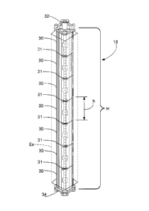
reactor core; during a SCRAM, the shutdown rods are rapidly fully inserted so
as to
rapidly stop the chain reaction. Control rods can also be designed to perform
both
gray rod and shutdown rod functions. Typically, a number of control rods are
connected with a single CRDM by an assembly including a connecting rod coupled
with the CRDM and terminating in a "spider" or other coupling element that
supports
the plural control rods. In such an assembly, the CRDM moves the plural
control
rods, along with the spider and the connecting rod, together as a unit.
[0003] When the control rods are partially or wholly withdrawn from the
reactor
core, they are supported by a control rod guide frame so as to ensure that the
control
rods remain in precise alignment with the aligned passages within the reactor
core.
In one typical guide frame configuration, a plurality of spaced apart guide
plates are
secured together by a frame. In operation, the control rods are guided by
openings in
the guide plates. Such a guide frame design has advantages including low
weight
CA 02825125 2013-04-18
WO 2012/054167
PCT/US2011/052495
- 2 -
and material cost, and limited impedance of primary coolant flow due to the
largely
open design. The use of guide plates to define the control rod guiding
surfaces also
provides a convenient planar form for the precision metalwork.
BRIEF SUMMARY
[0004] In one aspect of the disclosure, an apparatus comprises a control rod
guide
frame comprising a stack of two or more columnar elements defining a central
passage having a constant cross-section as a function of position along the
central
passage.
[0005] In another aspect of the disclosure, an apparatus comprises: a control
rod
guide frame comprising a stack of two or more columnar elements defining a
central
passage having a constant cross-section as a function of position along the
central
passage; a control rod assembly comprising at least one control rod parallel
aligned
with the central passage of the control rod guide frame; wherein the at least
one
control rod is movable into and out of the central passage of the control rod
guide
frame; and wherein any portion of the at least one control rod disposed in the
central
passage is guided by the central passage over the entire length of the portion
of the
at least one control rod that is disposed in the central passage
[0006] In another aspect of the disclosure, an apparatus as set forth in the
immediately preceding paragraph is disclosed, further comprising: a control
rod drive
mechanism (CRUM) operatively connected with the control rod assembly to
control
movement of the at least one control rod into and out of the central passage
of the
control rod guide frame; a nuclear reactor core; and a reactor pressure vessel
containing at least the nuclear reactor core, the control rod guide frame, and
the at
least one control rod; wherein as the at least one control rod moves out of
the central
passage of the control rod guide frame it moves into the nuclear reactor core
and as
the at least one control rod moves into the central passage of the control rod
guide
frame it moves out of the nuclear reactor core.
[0007] In another aspect of the disclosure, an apparatus comprises: a control
rod
assembly comprising a plurality of control rods; and a control rod guide frame
defining a central passage into which the at least one control rod can be
withdrawn,
the central passage providing continuous guidance along the entire length of
the
CA 02825125 2013-04-18
WO 2012/054167
PCT/US2011/052495
- 3 -
portion of each control rod of the plurality of control rods that is withdrawn
into the
central passage.
[0008] In another aspect of the disclosure, an apparatus comprises a control
rod
guide frame comprising a self-supporting stack of two or more columnar
elements
defining a central passage.
[0009] In another aspect of the disclosure, an apparatus comprises a control
rod
guide frame comprising a self-supporting stack of two or more columnar
elements
defining a central passage, wherein the control rod guide frame does not
include an
exoskeleton supporting the self-supporting stack of two or more columnar
elements.
[0010] In another aspect of the disclosure, an apparatus as set forth in
either one of
the two immediately preceding paragraphs is disclosed, wherein the columnar
elements include mating features that mate at abutments between adjacent
columnar elements of the stack. In another aspect of the disclosure, an
apparatus as
set forth in either one of the two immediately preceding paragraphs is
disclosed,
further comprising a control rod drive mechanism (CRDM) operatively connected
with a control rod assembly, and a nuclear reactor core, wherein the CRDM
moves
at least one control rod into and out of the nuclear reactor core under
guidance of the
control rod guide frame.
[0011] In another aspect of the disclosure, a method comprises forming at
least
one columnar element defining a central passage, and constructing a control
rod
guide frame including the at least one columnar element.
[0012] In another aspect of the disclosure, a method comprises forming a
plurality
of columnar elements each defining a central passage, and constructing a
control
rod guide frame by stacking the columnar elements end-to-end.
[0013] In another aspect of the disclosure, a method as set forth in either
one of the
two immediately preceding paragraphs is disclosed, wherein the forming
comprises
extruding at least one columnar element defining a central passage. In another
aspect of the disclosure, a method as set forth in either one of the two
immediately
preceding paragraphs is disclosed, wherein the forming comprises casting at
least
one columnar element defining a central passage. In another aspect of the
disclosure, a method as set forth in either one of the two immediately
preceding
paragraphs is disclosed, wherein the forming comprises forming at least one
CA 02825125 2013-04-18
WO 2012/054167
PCMJS2011/052495
- 4 -
columnar element defining a central passage using electrical discharge
machining
(ED M).
BRIEF DESCRIPTION OF THE DRAWINGS
[0014] The invention may take form in various components and arrangements of
components, and in various process operations and arrangements of process
operations. The drawings are only for purposes of illustrating preferred
embodiments
and are not to be construed as limiting the invention.
[0015] FIGURE 1 diagrammatically shows a perspective sectional view a lower
portion of an illustrative nuclear reactor pressure vessel including an
illustrative
continuous control rod guide frame.
[0016] FIGURE 2 diagrammatically shows a perspective view of the illustrative
continuous control rod guide frame of FIGURE 1 in context with a control rod
drive
mechanism (CRDM) and a bundle of control rods.
[0017] FIGURE 3 diagrammatically shows a perspective view of the control rod
guide frame of FIGURES 1 and 2.
[0018] FIGURE 4 diagrammatically shows a side sectional perspective view of
the
control rod guide frame of FIGURES 1-3, with the section revealing the
connecting
rod and coupling element.
[0019] FIGURES 5 and 6 diagrammatically show a perspective view and a side
sectional perspective view, respectively, of the coupling element of FIGURE 4.
[0020] FIGURE 7 diagrammatically shows a side view of one of the columnar
elements comprising the control rod guide frame of FIGURES 1-4.
[0021] FIGURES 8 and 9 show Section A-A and Section B-B, respectively, which
are indicated in FIGURE 7.
[0022] FIGURE 10 diagrammatically shows a side view of a stack of three
columnar elements of the embodiment shown in FIGURES 7-9, with the contained
coupling element and two representative control rods shown in phantom.
[0023] FIGURE 11 diagrammatically shows a perspective view of an alternative
control rod guidance structure comprising two spaced apart continuous control
rod
guide frames.
CA 02825125 2013-04-18
WO 2012/054167
PCT/US2011/052495
- 5 -
DETAILED DESCRIPTION OF THE PREFERRED EMBODIMENTS
[0024] An open control rod guide frame comprising spaced apart guide plates
secured together by an exterior frame has advantages including low weight and
material cost, limited primary coolant flow impedance, and manufacturing
convenience. However, numerous disadvantages of this guide frame configuration
are recognized herein. The spacing apart of the guide plates can potentially
allow
bowing of the control rods upon insertion if there is sufficient drag. Such
bowing can
cause the control rod assembly (that is, the plural control rods secured
together to a
connecting rod by a single spider or other coupling element) to get stuck
within the
guide frame and not allow it to be inserted into the nuclear core. Such a
failure in the
case of gray rods is at least a substantial inconvenience, and could require
opening
the reactor vessel for repair if the gray rods are essential to maintain
acceptable
reactivity control. In the case of hybrid and/or shutdown rods, bowing-induced
rod
insertion failure could hinder or even prevent successful SCRAM of a
malfunctioning
reactor, thus raising serious safety issues.
[0025] An issue related to the potential rod bowing is shutdown speed and
robustness. The rate at which the hybrid or control rods are inserted during a
SCRAM impacts the shutdown speed. Potential rod bowing in the spaces between
guide plates imposes an upper limit on the force (and hence speed) with which
the
control rods can be driven toward the reactor core, since too much force could
cause
control rod bending. The limited driving force can also adversely impact
reliability.
There is the potential for blockage or impediment to rod insertion into the
reactor
core. Sources of blockage or impediment include, for example, sediment or
other
contamination within the reactor vessel, or a burr or other defect in the
guiding
surfaces of the guide plate and/or the aligned passages within the reactor
core, or so
forth, possibly aggravated by thermal expansion during an elevated reactivity
incident. Any such blockage or impediment is less likely to be overcome by a
reduced driving force during rod SCRAM, thus raising the likelihood of a SCRAM
failure.
[0026] Another issue with using spaced apart guide plates is that the spider
or
other connecting element is not always aligned with any particular guide
plate. When
the spider is between spaced apart guide plates it is susceptible to movement
due to
CA 02825125 2013-04-18
WO 2012/054167
PCMJS2011/052495
- 6 -
any horizontal forces, for example due to horizontal primary coolant flow
components, or movement of the reactor vessel itself (for example, during an
earthquake, or at any time in the case of a maritime reactor). Any horizontal
movement of the spider increases likelihood of misalignment and consequent
failure
of the control rods attached to the spider.
[0027] Yet another issue with using spaced apart guide frames is the potential
for
flow induced vibrations acting on the control rods. For example, if the guide
plates
are treated as vibrational ''null" points, the spaced apart guide plates may
support
natural vibration modes having wavelengths (or "half-wavelengths") that are
multiples of the spacing between the guide plates. Such vibrations can
adversely
impact stability of the reactivity control and can contribute to material
fatigue and
ultimately to failure of the control rods.
[0028] It is recognized herein that these difficulties are alleviated by a
guide frame
providing continuous support. In such a case, rod bowing is suppressed or
prevented
entirely. This allows the use of greater force in driving the control rods
into the core
during a SCRAM, thus improving reactivity shutdown speed and reliability. The
spider or other connecting element is also supported by the guide frame at
every
point in its travel between the fully withdrawn and fully inserted control rod
positions.
Vibrations are also suppressed or eliminated entirely by the continuous
support.
[0029] With reference to FIGURE 1, a relevant portion of an illustrative
nuclear
reactor pressure vessel 10 includes a core former 12 located proximate to a
bottom
of the pressure vessel 10. The core former 12 includes or contains a reactive
core
(not shown) containing or including radioactive material such as, by way of
illustrative example, enriched uranium oxide (that is, UO2 processed to have
an
elevated 235U/238U ratio). A control rod drive mechanism (CRDM) unit 14 is
diagrammatically illustrated. The illustrative CRDM 14 is an internal CRDM
that is
disposed within the pressure vessel 10; alternatively, an external CRDM may be
employed. FIGURE 1 shows the single illustrated CRDM unit 14 as an
illustrative
example; however, more generally there are typically multiple CRDM units each
coupled with a different plurality of control rods (although these additional
CRDM
units are not shown in FIGURE 1, the pressure vessel 10 is drawn showing the
space for such additional CRDM units).
CA 02825125 2013-04-18
WO 2012/054167
PCT/US2011/052495
- 7 -
[0030] Below the CRDM unit 14 is a control rod guide frame 16, which in the
perspective view of FIGURE 1 blocks from view the connecting rod (not shown in
FIGURE 1). Extending below the guide frame 16 is a plurality of control rods
18.
FIGURE 1 shows the control rods 18 in their fully inserted position in which
the
control rods 18 are maximally inserted into the core former 12. In the fully
inserted
position, the spider or other connecting element is located at a lower
location 20
within the control rod guide frame 16 (hence also not visible in FIGURE 1). In
the
illustrative embodiment of FIGURE 1, the CRDM unit 14 and the control rod
guide
frame 16 are spaced apart by a standoff 22 comprising a hollow tube having
opposite ends coupled with the CRDM unit 14 and the guide frame 16,
respectively,
and through which the connecting rod (not shown in FIGURE 1) passes. The lower
end of the control rod guide frame 16 connects with a support plate 24, which
may
be an upper portion of the core former 12, or may be a separate plate mounted
above the upper end of the core former 12.
[0031] FIGURE 1 shows only a lower portion of the illustrative pressure vessel
10.
In an operating nuclear reactor, an open upper end 26 of the illustration is
connected
with one or more upper pressure vessel portions that together with the
illustrated
lower portion of the pressure vessel 10 form an enclosed pressure volume
containing the reactor core (indicated by the illustrated core former 12), the
control
rods 18, the guide frame 16, and the internal CRDM unit 14. In an alternative
embodiment, the CRDM unit is external, located above the reactor pressure
vessel.
In such embodiments, the external CRDM is connected with the control rods by a
control rod/CRDM coupling assembly in which the connecting rod extends through
a
portal in the upper portion of the pressure vessel.
[0032] With reference to FIGURE 2, the control assembly including the CRDM
unit
14, the control rod guide frame 16, the intervening standoff 22, and the
control rods
18 is illustrated isolated from the reactor pressure vessel. Again, the
control
rod/spider assembly is hidden by the control rod guide frame 16 and the
standoff 22
in the view of FIGURE 2.
[0033] With reference to FIGURE 3, the control rod guide frame 16 is shown in
perspective view and in isolation from the remaining components (such as the
CRDM, control rods, and so forth). The control rod guide frame 16 is a
continuous
CA 02825125 2013-04-18
WO 2012/054167
PCT/US2011/052495
- 8 -
guide frame rather than being constructed of spaced apart guide plates. The
guide
frames disclosed herein, in general, comprise one or more columnar elements.
The
illustrative control rod guide frame 16 includes an illustrative seven
columnar
elements 30, which are identical and are stacked to form the illustrative
control rod
guide frame 16. However, the number of columnar elements can be one, two,
three,
four, five, six, the illustrative seven, eight, nine, ten, or more. Moreover,
while the
illustrative seven columnar elements 30 are all identical to each other, this
is not
required. For example, different columnar elements may have different heights,
or
the different columnar elements may variously include or omit fluid flow
passages
(optional features discussed further elsewhere herein), or so forth.
[0034] Each pair of adjacent columnar elements 30 is connected at an abutment
31. (This is not pertinent in the limiting case in which the number of
columnar
elements equals one, since in that case there are no adjacent columnar
elements).
Since there are seven illustrative columnar elements 30, there are 7-1=6
abutments
31. More generally, if there are N stacked columnar elements then there are N-
1
abutments. The illustrative control rod guide frame 16 comprises a self-
supporting
stack of the (illustrative seven) columnar elements 30. There is no
exoskeleton
supporting the stack of columnar elements 30. (This is indicated
diagrammatically in
FIGURE 3 by showing an exoskeleton Ex in phantom so as to indicate that the
exoskeleton is omitted, that is, is not included in the control rod guide
frame 16.) In
other embodiments, however, it is contemplated to include an exoskeleton to
provide
some support for the stack of columnar elements.
[0035] Each columnar element 30 has a column height h, so that the
illustrative
control rod guide frame 16 in which the seven columnar elements 30 are
identical
has a column height H=7h. More generally, the height is the sum of the heights
of
the constituent columnar elements. In the limiting case of a guide frame
comprising
one columnar element, H=h. An upper end of the illustrative control rod guide
frame
16 includes an upper plate 32 that may connect with the CRDM unit 14 via the
standoff 22 (see FIGURE 2), while a lower end of the illustrative control rod
guide
frame 16 includes a lower plate 34 that connects with the support plate 24
(see
FIGURE 1) which is an upper part of, or proximate to, the fuel core former 12.
Although not shown, it is contemplated to include mounting blocks or other
CA 02825125 2013-04-18
WO 2012/054167
PCT/US2011/052495
- 9 -
intermediate components to facilitate the connection of the guide frame 16
with the
CRDM unit 14 and/or with the support plate 24. The foregoing height values
neglect
any height contribution of the upper and/or lower plates 32, 34 or of any
mounting
blocks or intermediate components.
[0036] With reference to FIGURE 4, a perspective sectional view of the
illustrative
control rod guide frame 16 is shown, with the section revealing a connecting
rod 40
and a coupling element 42 disposed inside the illustrative control rod guide
frame 16.
In FIGURE 4, the upper end of the connecting rod 40 is shown extending above
the
guide frame 16, in isolation. As will be understood by comparing FIGURE 4 with
FIGURES 1 and 2, the upper end of the connecting rod 40 extends into and
couples
with the CRDM 14. FIGURE 4 shows the configuration with the connecting
rod/coupling element assembly 40, 42 in their most "downward" position,
corresponding to the control rods (not shown in FIGURE 4) fully extended into
the
reactor core (as shown in FIGURES 1 and 2).
[0037] In some embodiments, a spider serves as the coupling element for
attaching
a plurality of control rods to a single connecting rod. A spider typically
comprises
metal tubes or arms (typically made of stainless steel) extending generally
radially
outward from a central attachment point at which the spider attaches with the
connecting rod, and optionally further includes additional supporting cross-
members
provided between the radially extending tubes. The spider is thus a
lightweight,
"spidery" structure having large lateral openings between the tubes or arms to
reduce the actual surface area oriented broadside to the SCRAM direction. In
illustrative FIGURE 4, however, the coupling element 42 is a coupling element
that
has substantial elongation along the SCRAM direction S, and is bulky rather
than
having a lightweight "spidery" configuration as in a conventional spider.
[0038] With reference to FIGURES 5 and 6, a perspective view and a
side-sectional perspective view, respectively, of the coupling element 42 is
shown.
The coupling element 42 includes a substantially hollow casing 50 having upper
and
lower ends that are sealed off by upper and lower casing cover plates 52, 54.
Four
upper casing cover plates 52 are illustrated in FIGURE 5 and two of the upper
casing
cover plates 52 are shown in the side-sectional perspective view of FIGURE 6.
The
tilt of the perspective view of FIGURE 5 occludes the lower cover plates from
view,
- 10 -
but two of the lower cover plates 54 are visible "on-edge" in the side-
sectional view
of FIGURE 6. The illustrative coupling element 42 includes four lower casing
cover
plates 54 arranged analogously to the four upper casing cover plates 52
illustrated in
FIGURE 5. The coupling element 42 is cylindrical with a cylinder axis parallel
with
the SCRAM direction S and a uniform cross-section transverse to the cylinder
axis.
That cross-section is complex, and defines a central passage 56 for coupling
with
the lower end of the connecting rod 40.
[0039] To increase the weight (or average density) of the coupling element 42,
the
casing 50 defines four cavities spaced radially at 90 intervals around the
central
passage 50. These cavities are filled with a filler 58 (only two filled
cavities are visible
in the sectional view of FIGURE 6) of a dense material. The cross-section of
the
hollow casing 40 also defines numerous small passages 60 (that is, small
compared
with the central passage 56), only some of which are labeled in FIGURES 5 and
6.
These small passages 60 pass completely through the casing 50, and provide
mounting points for attachment of the upper ends of the control rods 18.
[0040] The optional filler 58 increases the mass (or average density) of the
coupling
element 42 in order to increase SCRAM force and speed. The filler 58 comprises
a
heavy material, where the term "heavy material" denotes a material that has a
higher
density than the stainless steel (or other material) that forms the hollow
casing 50.
For example, the filler 58 may comprise tungsten, depleted uranium,
molybdenum,
or tantalum, by way of some illustrative examples. Alternatively, the cavities
can be
omitted and the entire coupling element 42 can be made of stainless steel, by
way of
example. Such a configuration still provides a substantial weight increase
over a
conventional lightweight, "spidery" spider due to the extension of the
coupling
element 42 along the SCRAM direction S and due to its more "filled"
configuration.
[0041] The illustrative "heavy" coupling element 42 is described in further
detail in
U.S Patent Application serial no. 12/862,124 filed August 24, 2010 and titled
"Terminal elements for coupling connecting rods and control rods in control
rod
assemblies for a nuclear reactor".
The illustrative "heavy" coupling element 42 has advantages such as
providing greater SCRAM force and consequently faster shutdown (in the case of
shutdown or hybrid control rods). However, more generally the control rod
guide
CA 2825125 2018-07-16
CA 02825125 2013-04-18
WO 2012/054167
PCMJS2011/052495
-11 -
frames 16 disclosed herein are suitably used with conventional spiders, or
with
coupling elements such as the illustrative coupling element 42, or with no
connecting
element at all (for example, a configuration in which a single control rod is
directly
coupled with the lower end of a connecting rod).
[0042] With returning reference to FIGURES 3 and 4 and with further reference
to
FIGURES 7-9, the illustrative control rod guide frame 16 is further described.
FIGURE 7 illustrates a side view of one columnar element 30. FIGURES 8 and 9
show respectively Section A-A and Section B-B indicated in FIGURE 7. As best
seen
in the sectional views of FIGURES 8 and 9, the columnar element 30 defines a
central passage 70 through the columnar element 30. The central passage 70 has
a
constant cross-section as a function of position along the central passage 70
(for
example, having substantially the same cross-section at the position of
Section A-A
and at the position of Section B-B, as shown in respective FIGURES 8 and 9).
Said
another way, the columnar element 30 (or, equivalently, guide frame 16
comprising
the stack of columnar elements 30) defines a central axis 72 (labeled in each
of
FIGURES 2, 4, 7, 8, and 9, where in FIGURES 8 and 9 the sectional views are
down the central axis 72) and the central passage 70 lies along the central
axis 72
and has a constant cross-section in the plane transverse to the central axis
at
positions along the central axis. The connecting rod 40 and the control rods
18 are
assembled to be parallel with the central axis 72 defined by the control rod
guide
frame 16. (Or, viewed in the alternative, the control rod guide frame 16 is
assembled
such that its central axis 72 is in parallel with the connecting rod 40 and
the control
rods 18). In the illustrative example (see FIGURE 4), the connecting rod 40
and
coupling element 42 are centered on the central axis 72. Such centering
provides
advantageous a balance-enhancing symmetry to the moving assembly; however, it
is also contemplated for the connecting rod and/or the spider or other
coupling
element to be positioned "off-center" respective to the central axis 72. It
will also be
noted that the SCRAM direction S is along (or parallel with) the central axis
72.
[0043] The central passage 70 is sized and shaped to receive the illustrative
coupling element 42 (or to receive the spider, in embodiments employing a
spider as
the coupling element) with a relatively small tolerance between the outer
surface of
the coupling element 42 (defined by the casing 50 in the illustrative example)
and the
CA 02825125 2013-04-18
WO 2012/054167
PCT/US2011/052495
- 12 -
surfaces of the central passage 70. The central passage 70 also includes
control rod
guidance channels 74 (labeled in FIGURE 8) which are parallel with the central
axis
72 and extend completely through the columnar element 30. Each control rod
guidance channel 74 is sized and positioned to receive a corresponding control
rod
of the plurality of control rods 18. Because the central passage 70 (including
the
guidance channels 74) has a constant cross-section as a function of position
along
the central passage, any portion of a control rod that is disposed in the
central
passage 72 (and more particularly in the control rod guidance channel 74
aligned
with that control rod) is guided by the central passage 70 (and more
particularly is
guided by the surfaces of the aligned control rod guidance channel 74) over
the
entire length of the portion of the control rod that is disposed in the
central passage.
Said another way, the control rod guidance channel 74 provides continuous
guidance for the entire portion of the control rod that is withdrawn into the
control rod
guide frame 16.
[0044] Phraseology such as "guidance" or "guiding surfaces" denote surfaces or
structures (e.g., the guidance channels 74) that guide the control rods
insofar as they
keep the control rod straight in its intended orientation within a specified
tolerance.
Typically, the guidance channels 74 have a slightly larger diameter as
compared with
the control rods, with the difference defining the allowed tolerance of
movement of
the guided control rod. If the control rod attempts to deviate beyond this
tolerance,
for example due to mechanical vibrational force or incipient bowing of the
control rod,
the control rod cams against the guiding surfaces of the guidance channels 74
to
prevent vibrational movement or bowing of the control rod beyond the allowable
tolerance. By making the guidance channel 74 slightly larger than the control
rod
diameter, the control rod is allowed to move down or up (that is, inserted
into or
withdrawn from the core) without frictional resistance from the guidance
channel 74.
However, it is also contemplated for the guidance channel 74 to be sized to
precisely
match the diameter of the control rod, so that the motion tolerance is
minimized at
the cost of some frictional resistance to control rod insertion or withdrawal.
The
foregoing sizing of the guidance channels 74 is also suitably chosen taking
into
account any differential thermal expansion of the control rods compared with
the
stainless steel or other material comprising the columnar element 30.
CA 02825125 2013-04-18
WO 2012/054167
PCMJS2011/052495
- 13 -
[0045] It will be noted that the illustrative guidance channels 74 do not form
complete closed cylindrical passages, but rather are partially "connected"
with the
main volume of the central passage 70. The central passage 70, including the
guidance channels 74, thus has a simply connected cross-section without any
"detached" passage cross-section portions. This allows the assembly including
the
coupling element 42 and the coupled bundle of control rods 18 to move
unimpeded
through the length of the central passage 70. Each guidance channel 74
surrounds
the circular cross-section of its guided control rod over a sufficient
perimeter so as to
prevent movement of the control rod beyond allowable tolerance in any
direction.
Moreover, while the illustrative guidance channels 74 are shaped to guide
control
rods having circular cross-sections, it is also contemplated for the control
rods to
have square, hexagonal, octagonal, or other cross-sections, in which case the
corresponding control rod guidance channels have correspondingly shaped
cross-sections that again are typically slightly enlarged compared with the
control rod
in correspondence with the allowable motion tolerance for the guided control
rod.
[0046] With continuing reference to FIGURES 7-9 and with further reference to
FIGURE 10, in embodiments (such as the illustrative embodiment) in which two
or
more columnar elements 30 are stacked to define the guide frame 16, the
central
passage 70 of each columnar element 30 is sized and shaped the same and is
aligned in the stacking so as to define a "stacked columnar passage" having a
constant cross-section as a function of position along the "stacked central
passage".
Said another way, guide frame 16 comprising the stack of columnar elements 30
defines the central axis 72, and the common central passage 70 of the stack
lies
along the central axis 72 and has a constant cross-section in the plane
transverse to
the central axis 72. The alignment of the columnar elements 30 includes
aligning the
control rod guidance channels 74 over the entire stack. This is
diagrammatically
shown in FIGURE 10, which illustrates a stack of three columnar elements 30.
Shown in phantom are two illustrative control rod guidance channels 74, with
the
coupling element 42 shown in phantom at a position in the middle columnar
element
30 of the stack. Two illustrative control rods 18 extend downward from the
coupling
element 42, and are partway withdrawn into the stack of columnar elements 30.
In
this position, portions of the two illustrative control rods 18 are disposed
in the
CA 02825125 2013-04-18
WO 2012/054167
PCT/US2011/052495
- 14 -
aligned control rod guidance channels 74 of the lowest columnar element 30 and
part of the middle columnar element 30 of the stack. Thus, these portions of
the two
illustrative control rods 18 are provided with continuous guidance along the
entire
length of the portions disposed in the stack.
[0047] With reference to FIGURES 3 and 7, the stack of columnar elements 30
comprising the control rod guide frame 16 is optionally a self-supporting
stack in
which the exoskeleton Ex is omitted. Toward this end, at each abutment between
adjacent columnar elements 30, one columnar element includes an abutting end
with
a first set of mating features and the other columnar element includes an
abutting
end with a second set of mating features. The first and second sets of mating
features are sized and shaped to mate together in the abutment. FIGURE 7
illustrates an example, in which the columnar element 30 has a first (upper)
abutting
end 80 having a first set of mating features which in the illustrative example
comprise
protruding stubs 82, and also has a second (lower) abutting end 84 having a
second
set of mating features which in the illustrative example comprise recessed
holes 86
(shown in phantom in FIGURE 7). When one columnar element 30 is stacked on top
of another, the recessed holes 86 in the abutting end 84 of the higher
columnar
element receive and mate with the protruding stubs 82 of the abutting upper
end 80
of the lower columnar element. Such mating features assist in ensuring proper
alignment, so that the central passages 70 of the stacked columnar elements
form a
continuous well-aligned passage through the entire guide frame 16. Depending
on
the nature of the mating features (e.g., the lengths of the stubs 82 and
depths of the
holes 86 in the illustrative example), the mating features may also provide
some
structural support contributing to the self-support of the stack.
[0048] In some embodiments, the stack of two or more columnar elements has a
constant outer perimeter as a function of position along the central passage
70. This
is the case for the illustrative stack of columnar elements 30. Such a
configuration
provides advantages such as enhanced interchangeability of the constituent
columnar elements, and simplified design of the usage of space within the
reactor
pressure vessel. However, it is also contemplated for the stack of two or more
columnar elements to have an outer perimeter that varies as a function of
position
along the central passage 70.
CA 02825125 2013-04-18
WO 2012/054167
PCMJS2011/052495
- 15 -
[0049] An advantage of the continuous guidance is that control rod bowing is
suppressed or eliminated, which allows for higher SCRAM driving force and
faster
reactor shutdown times. However, these advantages can be reduced if hydraulic
pressure builds up in the central passage 70 during a SCRAM so as to resist
insertion of the control rods. Such a pressure buildup may be enhanced if the
"bulky"
coupling element 42 is used, since it does not provide substantial openings
for flow
of the primary coolant fluid past the coupling element 42. One way to
alleviate
hydraulic pressure buildup in the central passage 70 during a SCRAM is to
employ a
spider or other coupling element having substantial openings for flow of the
primary
coolant fluid past the spider or other coupling element. However, this
approach
reduces the weight of the coupling element, which may be disadvantageous.
[0050] With reference to FIGURES 7 and 8, an additional or alternative way to
alleviate hydraulic pressure buildup in the central passage 70 during a SCRAM
is to
include fluid flow passages in one or more of the columnar elements to provide
fluid
communication between the central passage 70 and the exterior of the columnar
element. In the illustrative example, each columnar element 30 includes flow
passages comprising an upper set of slots 90 and a lower set of slots 92. The
slots
90, 92 are formed into the body of the columnar element 30, and are not
coextensive
with the height h of the columnar element 30 (and hence are not part of the
central
passage 70 which passes through the columnar element 30). In this regard,
notice
that illustrative Section A-A shown in FIGURE 8 passes through the slots 90,
and so
the slots 90 are visible in Section A-A. In contrast, illustrative Section B-B
shown in
FIGURE 9 passes between the slots 90 and the slots 92, and so no slots are
visible
in Section B-B. In the illustrative embodiment the control rod guide frame 16
comprises a stack of seven identical columnar elements 30, each of which
include
the slots 90, 92. More generally, however, it is contemplated to include fluid
flow
passages in only some of the columnar elements. The slot-shaped fluid flow
passages 90, 92 are illustrative examples, and other shapes and dimensions of
fluid
flow passages are also contemplated, such as holes (square, circular, or
otherwise-shaped), spiraling slots, or so forth.
[0051] With reference to FIGURE 11, the disclosed control rod guide frame
comprising a stack of one or more columnar elements defining a central passage
of
CA 02825125 2013-04-18
WO 2012/054167
PCMJS2011/052495
- 16 -
constant cross-section can be employed in a spaced-apart combination to obtain
the
substantial benefit of continuous guidance while reducing the total amount of
material. FIGURE 11 shows a control rod guidance structure comprising an upper
continuous control rod guide frame 161 and a lower continuous control rod
guide
frame 162 which are spaced apart by a spacer 96. The two continuous control
rod
guide frames 161, 162 are similar to the continuous control rod guide frame
16,
except that they include fewer columnar elements 30 and have variant
terminations.
More particularly, the upper continuous control rod guide frame 161 includes
three
columnar elements 30 and hence includes two abutments 31; while the lower
continuous control rod guide frame 162 includes four columnar elements 30 and
hence includes three abutments 31. The upper continuous control rod guide
frame
161 also omits the lower plate 34 in favor of a lower connection with the
spacer 96,
and similarly the lower continuous control rod guide frame 162 omits the upper
plate
32 in favor of an upper connection with the spacer 96. A potential advantage
of a
configuration such as that of FIGURE 11 is that the spacer 96 can be made with
large gaps to alleviate hydraulic pressure buildup in the central passage 70
during a
SCRAM, so that it serves a similar purpose to the slots 90, 92. A potential
disadvantage of the spacer 96 is that it presents a discontinuity in the
control rod
guidance. Thus, tradeoffs can be made between the "openness" of the control
rod
guidance structure (which is promoted by including more spacers of larger
height)
and the guidance continuity (which is promoted by fewer spacers of lower
height, or
no spacers at all as per the guide frame 16). It will be noted that in the
control rod
guidance structure of FIGURE 11, each of the constituent guide frames 161, 162
provide continuous guidance along their respective lengths (or heights). This
continuous guidance tends to bias the control rods into the "straight"
configuration,
which may suppress control rod bowing even in the unguided spacer 96.
[0052] The columnar elements 30 are suitably made of stainless steel, although
other materials are also contemplated. Manufacturing of the columnar elements
30
can employ various techniques, such as casting, extrusion, or electrical
discharge
machining (EDM). After initial formation by casting, extrusion, or EDM, the
castings
are optionally machined to meet specified tolerances. The recessed holes 86
are
suitably made by drilling, while the protruding stubs 82 are suitably
separately
CA 02825125 2013-04-18
WO 2012/054167
PCT/US2011/052495
- 17 -
manufactured components that are welded or otherwise secured in holes drilled
in
the columnar element 30. A suitable number of one or more columnar elements 30
are then stacked on top of each other, assisted by mating of the optional
mating
features 82, 86, to reach the specified overall height of the guide frame.
Alternatively,
as shown in FIGURE 11, two or more such continuous guide frames can be
assembled in a spaced apart fashion to reach the specified overall height.
[0053] An advantage of the disclosed self-supporting stacked continuous guide
frames is the optional elimination of an external frame (that is,
exoskeleton), with
anchoring of the guide frame provided by the upper and lower plates 32, 34
which
serve as attachment locations for both the guide frame and optional mounting
blocks
(not shown) that facilitate the guide frame mounting.
[0054] Another advantage of the disclosed stacked continuous guide frames is
reduced manufacturing labor and reduced welding of small components. The
illustrative guide frame 16 can be constructed using only tack welds at the
abutments
31 between adjacent columnar elements 30. Some welding may also be applied at
the interface of the stack and the upper and lower plates 32, 34, and at any
mounting
blocks used in the guide frame mounting. The optional fluid flow passages 90,
92 are
suitably cut into the sides of the columnar elements 30 to reduce the
likelihood of
hydraulic pressure buildup in the central passage 70. It is also noted that
such fluid
flow passages 90, 92 may have the advantage of reducing the impact of the
guide
frame 16 on cross-flow of the primary coolant fluid.
[0055] As already mentioned, the columnar element 30 may be suitably formed by
casting, extrusion, or EDM. In the latter technique (Electrical Discharge
Machining or
EDM), the columnar element 30 is cut out of a solid block of material (e.g., a
solid
block of stainless steel) to represent the geometry. Optionally, a rougher
casting is
first formed and the EDM is then used to refine the rough casting toward the
final
shape of the columnar element 30. Some suitable EDM manufacturing techniques
include wire-cut EDM.
[0056] The constant cross-section central passage 70 and optional constant
outer
perimeter of the columnar element 30 is naturally conducive to formation by
extrusion, which is another suitable approach for forming the columnar element
30.
The use of extrusion to form the columnar element 30 is advantageous due to
low
CA 02825125 2013-04-18
WO 2012/054167
PCT/US2011/052495
- 18 -
cost, and because extrusion does not constrain the maximum height h of the
columnar element 30. (By way of contrasting example, casting constrains the
maximum height h to the maximum feasible casting mold size). This makes
extrusion
particularly well-suited for forming a columnar element of large height h,
such as is
typically needed in the case of a guide frame comprising a single columnar
element.
Using a single columnar element reduces the amount of labor and welding
involved
with manufacturing the guide frame, and eliminates the need to align a
plurality of
stacked columnar elements.
[0057] While a continuous constant cross section is preferred, in one
alternative
embodiment the cross section geometry tapers slightly along a vertical axis of
at
least on columnar element such that a degree of hydraulic resistance may be
utilized
to enable additional control of the component velocity during SCRAM. In
another
alternative embodiment the cross section geometry may vary slightly between
and
amongst multiple columnar elements.
[0058] The preferred embodiments have been illustrated and described.
Obviously, modifications and alterations will occur to others upon reading and
understanding the preceding detailed description. It is intended that the
invention be
construed as including all such modifications and alterations insofar as they
come
within the scope of the appended claims or the equivalents thereof.