Note: Descriptions are shown in the official language in which they were submitted.
81772767
SYSTEM AND METHOD FOR AUTOMATICALLY
ADJUSTING GAS SENSOR SETTINGS AND PARAMETERS
Cross-Reference to Related Applications
[0001]
This application is a continuation-in-part of US Non-Provisional Patent
Application No. 13/018,039 filed on January 31, 2011 entitled SYSTEM AND
METHOD
FOR AUTOMATICALLY ADJUSTING GAS SENSOR SETTINGS AND PARAMETERS.
[0002]
[0003]
1
Date Recue/Date Received 2020-05-15
CA 02825314 2013-07-19
WO 2012/106275
PCT/US2012/023207
[0003] In order for a particular sensor to detect a desired gas in a
particular
concentration range, and to transmit that information in a form readily
understood by
a remote transmitter, the sensor's output signals must be properly
conditioned.
Currently, sensor signal conditioning is accomplished by using discreet
components
(i.e. resistors, capacitors, operational amplifiers, etc.) to filter and
amplify a specific
sensor's output prior to performing a conversion to the digital domain for
further
processing. In one example, signals from electrochemical sensors are typically
conditioned using the well-known potentiostat circuit. The drawback to using
discrete
components, however, is that the arrangement of such components is often
specific to
a particular type of sensor, and also to a particular gas being sensed as well
as a
desired concentration range. Thus, developing conditioning circuits for a wide
range
of gases and ranges requires changing the values of these components to
achieve
optimum analogue signal conditioning. This, in turn, requires a wide variety
of
conditioning circuits to cover ranges of potential interest. As a result, a
large number
of sensors of differing types, and of differing concentration range
capacities, are
manufactured and stocked to meet the associated wide variety of field
applications.
Moreover, most sensors operate in combination with an associated transmitter
unit.
Due to the specialized nature of the described sensors, such transmitters
often only
work with a single sensor type. As such, current systems require that a
similarly large
number of different transmitters are also manufactured and stocked.
[0004] In addition, when current remote transmitter and sensors are
installed
and/or replaced, they are individually adjusted to ensure they are
appropriately
calibrated, and also to ensure that they are in proper working condition.
Currently, for
remote transmitter and sensor applications this adjustment/verification
process is a
2
CA 02825314 2013-07-19
WO 2012/106275
PCT/US2012/023207
two-person effort in which one person stands at the sensor location reading a
digital
voltage meter, and a second person at the transmitter adjusting a manual
potentiometer to achieve a desired output voltage for supplying the sensor.
When this
operation takes placed in a hazardous area, it can require that the area be
declassified
so that the transmitter can be opened to access the manual potentiometer. Much
the
same is true for integral transmitter and sensor applications, in which one
person reads
a digital voltage meter and adjusts a manual potentiometer at the transmitter
to
achieve a desired output voltage for supplying the sensor. This can also
undesirably
involve declassifying the associated hazardous area to open the transmitter to
access
the manual potentiometer.
[0005] It will further be appreciated that sensors undergo sensitivity
losses
over time. Present systems are not able to provide automatic recognition and
adjustment of sensors to compensate for such losses in sensitivity. This, in
turn, can
lead to premature disposal of sensors that drop below a desired sensitivity
threshold.
Since such sensors ostensibly would continue to function desirably if their
loss in
sensitivity could be compensated for, current systems produce unnecessary
waste.
[0006] Accordingly, there is a need for an improved environmental
sensing
system that: enables a single transmitter to recognize and accept a plurality
of
different sensor types, automatically adjusts installed sensors to reduce or
eliminate
the need for manual adjustment, automatically calibrates sensors to enable a
single
sensor to accommodate a variety of different sensing ranges. enables a sensor
to be
calibrated at a single value and then be used at a variety of values, and
enables
automatic adjustments to extend sensor lifetime.
3
CA 02825314 2013-07-19
WO 2012/106275
PCT/US2012/023207
[0007] In addition, a
type of environmental sensing system includes a
transmitter portion connected to an associated sensor portion by a cable.
The
transmitter portion transmits information received from the sensor portion to
a
wireless network, for example. The sensor portion may be located in a
hazardous
and/or combustible environment remote from the transmitter portion. Further,
the
transmitter and sensor portions each include a gland arrangement having
multiple
holes through which wires extend.
[0008] It is frequently
desirable to "hot swap" the sensor during use, i.e.
replace the sensor without declassifying the hazardous area, in the event that
the
sensor has lost sensitivity, for example. However, removing the sensor may
cause
generation of a spark or an electrical arc in the connection between the
transmitter and
sensor circuitry. These sparks could ignite a potentially explosive
atmosphere.
Summary of the Disclosure
[0009] An environmental
sensing system solving one or more of the
aforementioned problems is disclosed. Specifically, a system is disclosed
including:
(1) an automatic sensor excitation voltage adjustment feature, (2) a multi-
range
concentration feature, and (3) a single calibration feature. The automatic
sensor
excitation voltage adjustment feature may include a transmitter having an
associated
microprocessor that provides an initial voltage to an associated sensor. The
sensor
also may have an associated microprocessor, and as the voltage changes, a
correction
signal may be relayed from the sensor microprocessor to the transmitter
4
CA 02825314 2013-07-19
WO 2012/106275
PCT/US2012/023207
microprocessor. The correction signal may be used by the transmitter
microprocessor
to adjust the voltage being applied to the sensor to a desired value. The
multi-range
concentration sensor feature may include an amplifier associated with the
sensor/microprocessor to create gain settings which can then be used to
optimize
sensor resolution by changing a gain value associated with the sensor. This,
in turn,
may enable a single sensor to be used for a variety of different concentration
ranges,
as desired by a user. The single calibration feature enables a sensor to be
calibrated at
a single gas concentration value, and thereafter be used for a variety of
different
concentration range applications.
[0010] A system is
disclosed for recognizing and adjusting sensor voltage by
using digital potentiometers, preferably without human intervention and
without the
need to declassify a hazardous area. The system may
include a gas
detector/transmitter power supply circuit comprising an adjustable power
supply with
a pair of digital potentiometers. One potentiometer can be used for coarse
voltage
adjustment, and the second potentiometer can be used for fine voltage
adjustment. An
output voltage from this power supply circuit is referred to as Vadjust, and
is used to
power a sensor associated with the transmitter. This arrangement enables a
single
transmitter design to be used with a multiplicity of different sensor types
and ranges,
as the power supply circuit is able to automatically adjust the sensor
excitation
voltage (Vadjust) to a specific value associated with the particular sensor
being used. It
can also compensate for voltage variations due to environmental changes and
voltage
drop in the intervening cable. The disclosed system enables sensors to be
replaced
under power, without declassifying the associated area. In addition, the
disclosed
system can reduce the overall cost of ownership by enabling replacement of
only the
CA 02825314 2013-07-19
WO 2012/106275
PCT/US2012/023207
sensor kernel at sensor end of life, as opposed to current systems which
require
replacement of an entire sensor unit.
[0011] A system is disclosed for detecting the presence of a gas,
comprising a
transmitter portion, a sensor portion, and a variable voltage supply
associated with the
transmitter portion and the sensor portion. The transmitter portion may
receive
information from the sensor portion regarding a received voltage. The
transmitter
portion may also adjust the supplied voltage in response to the information
received
from the sensor portion.
[0012] A method is disclosed for adjusting sensor excitation voltage.
The
method may include providing, at a transmitter portion, an operating voltage
to a
sensor portion, receiving, at the transmitter, a signal from the sensor
portion
indicating a voltage required for operation of the sensor portion, and
adjusting, at the
transmitter, the operating voltage provided to the sensor portion.
[0013] A universal gas sensor/transmitter unit is disclosed. The unit
may
include a sensor portion including a sensor kernel and a processor configured
to read a
received excitation voltage. The unit may also include a transmitter portion
having a
recess configured to engage the external surface geometry of the sensor. The
transmitter may include a transmitter processor and at least one power supply
circuit
for providing adjustable power to the sensor when the enclosure is engaged
with a
recess of the transmitter. The adjustable power supply circuit may include at
least one
potentiometer controllable by the processor to adjust a power supplied to the
sensor
portion.
6
CA 02825314 2013-07-19
WO 2012/106275
PCT/US2012/023207
[0014] A method for calibrating a sensor is disclosed. The method may
include setting an original zero offset and a spanning of a sensor at a first
gain setting;
obtaining a zero offset at a second gain setting; obtaining a ratio of the
original zero
offset to the zero offset at the second gain setting; and scaling a
calibration factor by
the ratio to enable operation of the sensor in an operating range associated
with the
second gain setting.
[0015] A method for providing replacement guidance for a sensor is also
disclosed. The method may include determining a reduction of sensitivity for a
sensor, trending said reduction of sensitivity over time, and adjusting a gain
parameter
associated with the sensor to compensate for the reduction of sensitivity.
[0016] A method for adjusting an operating range for a sensor is
disclosed.
The method may include providing an amplifier associated with the sensor,
providing
a table of gain settings for the amplifier, and selecting a gain setting from
the table to
optimize a resolution in an analog to digital converter associated with the
sensor.
Selecting a gain setting may adjust the sensor to one of a plurality of pre-
determined
operating ranges.
[0017] In addition, a system for detecting the presence of a gas is
disclosed.
The system includes a sensor portion for sensing a target gas and providing
signals
indicative of the gas, wherein the sensor portion is replaceable. The system
also
includes a transmitter portion for transmitting information received from the
sensor
7
81772767
portion to a network. Further, the system includes a barrier circuit for
providing intrinsically
safe power and communication signals to the sensor portion.
[0018] A system for detecting the presence of a gas is disclosed, whereby
the system
may be combined into a network having a common transmitter portion, with one
or more
barrier circuits, receiving information from a plurality of sensor portions.
[0018a] According to one aspect of the present invention, there is provided
a system for
configuring a sensor for detecting the presence of a gas, the system
comprising: a transmitter
portion including a transmitter processor; a sensor portion including a sensor
processor, the
sensor processor being in communication with the transmitter processor using
digital
communication; and a variable voltage supply associated with the transmitter
portion and the
sensor portion, the variable voltage supply including a plurality of
potentiometers, each of the
plurality of potentiometers configured to adjust an operating voltage that is
output to the
sensor portion for operation of the sensor; the sensor processor being
configured to
communicate a stored voltage value for operation of the sensor to the
transmitter processor
using the digital communication; and the transmitter processor being
configured to set at least
one of the plurality of potentiometers to at least one value to provide, to
the sensor portion, an
operating voltage for operation of the sensor that corresponds to the stored
voltage value.
[0018b] According to another aspect of the present invention, there is
provided a
method for adjusting sensor excitation voltage, comprising: receiving, at a
transmitter portion
including a transmitter processor, a stored voltage value from a sensor
processor of a sensor
portion of a gas sensing system that is in digital communication with the
transmitter portion,
the stored voltage value indicating a voltage for operation of the sensor
portion; providing, at
the transmitter portion, an operating voltage corresponding to the stored
voltage value to a
sensor portion; and automatically adjusting, at the transmitter portion, the
operating voltage
provided to the sensor portion using at least one of a first and second
potentiometers of a
plurality of potentiometers of a variable voltage supply.
8
CA 2825314 2019-02-11
81772767
[0018c] According to still another aspect of the present invention, there
is provided a
universal gas sensor/transmitter unit, comprising: a transmitter portion
having a recess
configured to engage a sensor portion to sense gas, the transmitter including
a transmitter
processor and at least one power supply circuit for providing adjustable power
to the sensor
when the sensor portion is engaged with a recess of the transmitter portion;
the sensor portion
including a sensor processor configured to communicate a stored voltage value
for operation
of the sensor to the transmitter processor using digital communications; and
the power supply
circuit including a plurality of potentiometers controllable by the
transmitter processor to
automatically adjust the power supplied to the sensor portion for operation of
the sensor, the
transmitter processor configured to set at least one of the plurality of
potentiometers to a value
to provide, to the sensor portion, an operating voltage for operation of the
sensor that
corresponds to the stored voltage value.
[0018d] According to yet another aspect of the present invention, there is
provided a
system for detecting the presence of a gas, comprising: a transmitter portion
including a
transmitter processor; a sensor portion including a sensor processor, the
sensor portion
adapted to sense gas; and a variable voltage supply associated with the
transmitter portion and
the sensor portion, the variable voltage supply including a plurality of
potentiometers to
enable coarse and fine voltage adjustment; the sensor processor configured to
communicate a
required voltage to the transmitter processor, the transmitter processor
configured to set at
least one of the plurality of potentiometers to a default value to deliver an
operating voltage
corresponding to the required voltage to the sensor portion, the sensor
processor further
configured to measure an actual voltage received from the transmitter
processor and to
communicate the actual voltage to the transmitter portion, the transmitter
processor further
configured to compare the actual voltage to the required voltage and to adjust
the operating
voltage toward the required voltage.
[0018e] According to a further aspect of the present invention, there is
provided a
method for adjusting sensor excitation voltage, comprising: a sensor portion
of a gas sensing
system communicating a required voltage to a transmitter portion of the gas
sensing system;
providing, at the transmitter portion, an operating voltage corresponding to
the required
8a
CA 2825314 2020-01-29
81772767
voltage to the sensor portion by setting at least one of a plurality of
potentiometers of a
variable voltage power supply to a default value; measuring, at the sensor
portion, an actual
voltage; receiving, at the transmitter portion, a signal from the sensor
portion indicating the
actual voltage; comparing, at the transmitter portion, the actual voltage to
the operating
voltage; and automatically adjusting, at the transmitter portion, the
operating voltage toward
the required voltage.
1001811 According to yet a further aspect of the present invention, there
is provided a
universal gas sensor/transmitter unit, comprising: a transmitter portion
having a recess
configured to engage a sensor portion adapted to sense gas, the transmitter
portion including a
transmitter processor and at least one power supply circuit for providing
adjustable power to
the sensor portion when the sensor portion is engaged with the recess of the
transmitter
portion, the power supply circuit including a first potentiometer for coarse
voltage adjustment
and a second potentiometer for fine voltage adjustment, the first and second
potentiometers
controllable by the transmitter processor to automatically adjust the power
supplied to the
sensor portion; the sensor portion including a sensor processor configured to
communicate a
required voltage to the transmitter processor, the transmitter processor
configured to set at
least one of the first and second potentiometers to a default value to deliver
an operating
voltage corresponding to the required voltage to the sensor portion, the
sensor processor
further configured to measure an actual voltage received from the transmitter
portion and to
communicate the actual voltage to the transmitter processor, the transmitter
processor further
configured to compare the actual voltage to the required voltage and to adjust
the operating
voltage toward the required voltage.
Brief Description of The Drawings
100191 By way of example, a specific embodiment of the disclosed device
will now be
described, with reference to the accompanying drawings, in which:
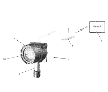
100201 FIG. 1 is an illustration of an exemplary transmitter with a
single sensor
combination;
8b
CA 2825314 2020-01-29
,
81772767
[0021] FIG. 2 is an illustration of an exemplary transmitter portion
of FIG. 1
associated with multiple detector head portion with a plurality of different
sensor portion
types;
[0022] FIG. 3 is a cross section view of an exemplary detector head
portion assembly
which contains a sensor portion assembly for use with the transmitter portion
of FIG. 1;
8c
CA 2825314 2020-01-29
CA 02825314 2013-07-19
WO 2012/106275
PCT/US2012/023207
[0023] FIGS. 4A-4C are exploded views of respective sensor portion
assemblies for use with the detector head portion FIG. 3 for use in the
transmitter
portion of FIG. 1;
[0024] FIG. 5 is an exploded view of the transmitter portion of FIG. 1;
[0025] FIG. 6 is a system diagram of the transmitter/sensor combination
of
FIG. 1;
[0026] FIG. 7 is system board level diagram of the transmitter/sensor
combination of FIG. 1;
[0027] FIG. 8 is a block diagram for the sensor portion of FIG. 4;
[0028] FIG. 9 is a block diagram of an exemplary power supply
arrangement
for the transmitter/sensor combination of FIG. 1;
[0029] FIG. 10 is a circuit diagram of an exemplary adjustable power
supply
for use with the transmitter/sensor combination of FIG. 1;
[0030] FIG. 11 is an exemplary circuit is shown for providing a
reference
voltage used by the transmitter processor;
[0031] FIG. 12 is a schematic of an exemplary gas transmitter/sensor
processor;
9
CA 02825314 2013-07-19
WO 2012/106275
PCT/US2012/023207
[0032] FIG. 13 is a schematic of an exemplary sensor processor;
[0033] FIG. 14 is a flowchart illustrating an exemplary embodiment of
the
disclosed method;
[0034] FIG. 15 is a block diagram for the arrangement shown in FIG 2;
[0035] FIG. 16 is a transmitter portion block diagram;
[0036] FIG. 17 is a sensor portion block diagram;
[0037] FIG. 18 is a schematic of a transmitter power barrier circuit for
providing an intrinsically safe (IS) power signal; and
[0038] FIG. 19 is a schematic of a transmitter communications barrier
circuit
for providing an IS communication signal.
Detailed Description
[0039] The disclosed system and method takes advantage of advances in
microelectronics and performs final signal conditioning of a sensor using
amplification built into microprocessors. This amplification can be
software
controlled to be arranged in either a differential or additive mode.
Additionally, the
level of gain can be adjusted in discrete levels, thus allows a wide range of
input
CA 02825314 2013-07-19
WO 2012/106275
PCT/US2012/023207
signals to be accommodated in a single circuit without resorting to changing
in
discrete components.
[0040] Several applications are realizable. First, a single sensor can
be built
for a specific gas, and the range of the sensor can be optimized for a
particular
application. For example, one sensor can be provided in either a 0-10 ppm or 0-
100
ppm range simply by changing software parameters. Secondly, variations in
sensor
sensitivity can be accommodated over a wider range, leading to greater
manufacturing
throughput. Previously, sensor kernels had to be screened to ensure their
sensitivity
could be accommodated by a particular fixed circuit design. Now a wider
variability
in sensitivity can be utilized, leading to less manufacturing waste. Lastly,
as sensors
are subjected to normal use, their sensitivities degrade. With prior designs,
once the
sensor's sensitivity had degraded to the point the fixed circuit cannot
compensate for
this degradation, the sensor had reached the end of its useful life. The
current system
and method can be used to compensate for sensor sensitivity degradation beyond
the
traditional limit by adjusting gain upward. This has the advantage of reducing
life
cycle cost for a gas detector by reducing the total number of sensor
replacements.
[0041] As previously noted, current systems utilize fixed circuit
designs for
each range of a target gas. In practice, sensors need to be calibrated on a
recurring
basis to ensure accuracy. Calibration is performed at 2 points: one with no
gas
present (zero), and one point within the sensor's range (span). where the span
is
typically 25-75% full scale. In an installation with sensors of various
ranges, this
requires the presence of multiple calibration gasses at different
concentrations.
11
CA 02825314 2013-07-19
WO 2012/106275
PCT/US2012/023207
[0042] With the disclosed system and method, the calibration variables
are
scaled to different ranges within the sensor. This enables calibration using
one
concentration of calibration gas and then adjusting the range of the sensor
for the
particular application. This has the advantage of enabling calibration of
different
range sensors using one common calibration gas. As will be appreciated, this
reduces
the number of different concentration calibration gasses required, and/or it
eliminates
the need to use a gas concentration that is more widely available than another
for a
specialized application.
[0043] A gas sensor/transmitter combination is disclosed that recognizes
and
adjusts sensor voltage by using digital potentiometers, preferably without
human
intervention and without declassifying a hazardous area. A etas
sensor/transmitter
power supply circuit includes an adjustable power supply with two digital
potentiometers. One potentiometer is for coarse voltage adjustment and the
second
potentiometer is for fine voltage adjustment. The output voltage of this power
supply
circuit is called Vadjust and aids in powering the sensor associated with the
transmitter.
[0044] Referring now to FIG. 1, a transmitter/sensor combination 1 is
shown
comprising a detector head portion 2 and a transmitter portion 4. The
transmitter
portion 4 may be configured to transmit information received from the detector
head
portion 2 to a wireless network 6 via a wireless link 8. The wireless link 8
can be any
of a variety of protocols, including, ISA 100.11a, wireless HART and the like.
The
wireless network 6 may distribute information received from the transmitter
portion 4
to one or more local or remote alarms, and one or more local or remote
monitoring
stations via intranet, Internet, Wi-Fi, or other network arrangement. It will
be
12
CA 02825314 2013-07-19
WO 2012/106275
PCT/US2012/023207
appreciated that although FIG. 1 illustrates a wireless connection to network
6, that
the invention is not so limited. Thus, the connection could be hard wired,
protocols
including Modbus, HART, Foundation fieldbus, Protibus and the like.
[0045] Referring to FIG. 3, detector head portion 2 includes a sensor
portion
200. As will be understood, the primary purpose of the sensor portion 200 is
to sense
a target gas and provide signals representative of the concentration of that
gas to the
transmitter portion 4. The primary purpose of the transmitter portion 4 is to
collect
information from the detector head portion 2 and to transfer that data
upstream.
Upstream devices may include controllers, gateways, converters and similar
devices.
[0046] In addition to remote transmission of sensor data, the
transmitter
portion 4 may include a local display 10 for providing local indication of
sensor
operation. In some embodiments, the transmitter portion 4 may be configured to
accept a plurality of detector head portions to provide an expanded area
coverage.
FIG. 2 shows a transmitter portion 4 hardwired to a plurality of detector head
portions
2A-2C representing a plurality of different sensor types that can be used with
the
transmitter portion 4. Indeed, although the description will proceed in
relation to a
transmitter portion 4 associated with a single detector head portion 2, it
will be
appreciated that the transmitter portion 4 may be associated with, and accept
signals
from, a plurality of detector head portions 2A-2C at once.
[0047] As will be appreciated, the detector head portion 2 (or detector
head
portions, where multiple sensors are used with a single transmitter) may be
any of a
variety of known sensor types, a non-limiting exemplary listing of such types
13
CA 02825314 2013-07-19
WO 2012/106275
PCT/US2012/023207
including an IR gas sensor, a catalytic bead sensor, an electro-chemical
sensor, a
photo-ionization sensor, and a metal-oxide sensor.
[0048] In practical application, particular detector head portions 2 may
be
used to detect a wide variety of toxic gases, an exemplary listing of which
includes,
but is not limited to, Ammonia, Arsine, Boron Trichloride, Boron Trifluoride,
Bromine, Carbon Dioxide, Carbon Monoxide, Chlorine, Chlorine Dioxide,
Diborane,
Fluorine, Germane, Hydrogen, Hydrogen Bromide, Hydrogen Chloride, Hydrogen
Cyanide, Hydrogen Fluoride, Hydrogen Sulfide, Methanol, Methyl Mercaptan,
Methyl Iodide, Nitric Oxide, Nitrogen Dioxide, Nitrogen Trifluoride, Oxygen,
Ozone, Phosphine, Silane, Silicon Tetrafluoride, Sulfur Dioxide,
Tetraethyloxysilane
(TEOS), and Tungsten Hexafluoride.
[0049] In addition, particular detector head portions 2 may be used to
detect a
wide variety of combustible gases, a non-limiting exemplary listing of which
includes
Acetone, Benzene, Butadiene, Butane, Ethane, Ethanol, Ethylene, Hexane,
Hydrogen,
Isobutanol, Isopropyl Alcohol, Methane, Methanol, Methyl Ethyl Ketone (MEK),
Pentane, Propane, Propylene, Toluene, and Xylene.
[0050] A benefit of the disclosed arrangement is that a single detector
head
portion 2 may quickly accept any of a variety of sensor portions 200. Thus, as
shown
in FIGS. 4A-4C, the sensor portion 200 may include internal sensing components
such as a sensor kernel 12, mounted within an upper sensor enclosure 22. And
although different sensor portions 200 may include different sensor kernels
12, as
well as additional processing components, all of the different sensor kernels
12 will be
14
CA 02825314 2013-07-19
WO 2012/106275
PCT/US2012/023207
fit within upper and lower sensor enclosures 22, 14, thus allowing the sensor
portion
200 to be of a single size and shape for all applications.
[0051] The lower sensor enclosure 14 may be arranged to allow simple
installation of a particular sensor kernel 12 and associated components. This
can
make it possible to replace a sensor kernel 12 without requiring the remaining
components of the sensor portion 12 to be replaced.
[0052] Thus arranged, to engage the detector head portion 2 with the
transmitter portion 4, the upper region 16 of the detector head portion 2 is
inserted
into a recess (not shown) in the transmitter portion 4, and the end cap 18 of
the
detector head portion 2 engages the recess and locks the sensor portion 200 to
the
detector head portion 2. The end cap 18 may have one or more recesses or other
geometry suitable for receiving an o-ring, gasket or the like to seal the
sensor portion
200 to the detector head portion 2. This sealing arrangement protects the
internal
sensor and components from potentially harsh exterior environments. A sensor
portion 200 can include self-aligning features (e.g., keyed interaction with
the
transmitter) that can further facilitate quick installation and replacement of
sensor
portions 200. Retaining features, such as external threads and the like, can
also be
provided to ensure firm engagement of the sensor portion 200 with the detector
head
portion 2.
[0053] FIGS. 4A-4C show a plurality of sensor portions 200 used for
sensing
different gas types. As can be seen, each of the sensor portions 200 includes
a lower
sensor enclosure 14, an upper sensor enclosure 22, a sensor kernel 12, a
contact board
CA 02825314 2013-07-19
WO 2012/106275
PCT/US2012/023207
24, a sensor printed circuit board (PCB) 26, and an interface PCB 28. As can
be seen,
the sensor kernel 12 has a different size/geometry for each of the different
sensor
portions 200. Such differences can be accommodated by the lower sensor
enclosure
14 which can have an internal geometry configured to receive the specific
sensor
kernel 12, but which has a common external configuration so that it can be
received
by the upper sensor enclosure 22. These differences also may be accommodated
by
the contact board 24, which may include receptacles 25 (see FIG. 4A) to plug
in the
specific sensor kernel 12. This allows the sensor portion 200 to be of a
single size and
shape for all applications.
[0054] As can be seen, a variety of different sized/shaped sensor
kernels can
be accommodated without impacting the external arrangement of the sensor
portion
200. Thus, each of the sensor portions 200 of FIGS. 4A-C can fit to the
detector head
portion 2 in exactly the same physical manner.
[0055] The sensor PCB 26 may be unique to each sensor kernel 12, and as
such it may include a sensor processor 30, as well as a conditioning circuit
32 that
performs conditioning of the signals received from the sensor kernel 12. For
example, the conditioning components 32 may convert the signal from the sensor
kernel in 1.1A per ppm to a voltage level useable by the sensor processor's
analog to
digital converter. The interface PCB 28 provides an interface between the
sensor
PCB 26 and the detector head portion 2. The interface PCB 28 may include a pin
arrangement 34 common to all sensor portions 200 that is configured to be
received
by the detector head portion 2.
16
CA 02825314 2013-07-19
WO 2012/106275
PCT/US2012/023207
[0056] As arranged, in one embodiment the sensor portion 200 may
constantly
measure a local target gas concentration, supply voltage, and ambient
temperature and
report a temperature compensated gas concentration, when requested, to the
transmitter portion 4.
[0057] FIG. 5 shows the internal components of the transmitter portion
4,
which may include a display 10, processor board 36, relay/network board 38,
power
supply board 40, and intrinsic safety (IS) barrier 42. One or more plug-in
blocks 44
may also be included for providing a variety of connectivity functions for the
transmitter portion 4. The plug-in blocks 44 may be used to provide power,
relays,
remote acknowledge, communications and detector head connections.
[0058] FIG. 6 shows a logical arrangement of an exemplary
transmitter/detector head/sensor combination 1 in accordance with one or more
embodiments. In the illustrated embodiment, the transmitter portion 4
comprises a
processor 46 that connects to the sensor portion 200 via digital communication
48,
and it relays the output of the sensor portion 200 through a variety of
communications
means. A display 10 is provided to permit local monitoring of data as well as
setting
parameters and setting system parameters associated with process changes and
calibration. An expansion port 50 is provided to enable methods of
communication
beyond the 4 to 20 milliamp signal and MUDD US. Memory 52 is provided to allow
a
history of process data, calibration data and expanded user information.
Watchdog
circuits 54 are provided to assure enhanced reliability. One or more
additional
circuits 56 can be provided for factory use to program and test the device
during
17
CA 02825314 2013-07-19
WO 2012/106275
PCT/US2012/023207
production. Interface/power supply 40 provides power to the transmitter
portion 4
and the sensor portion 200.
[0059] The inputs to the transmitter portion 4 can be HART, Serial
communication from a host, serial communication from sensors, PC communication
from on-board and off-board devices, SPI communication from on-board and off-
board devices and contact closures from magnetic switches located on the
display 10.
The outputs from the transmitter portion 4 include LEDs on the display 10, LCD
on
the display 10, alarm relays, 4-20 milliamp current loops, MODBUS
communication
with external hosts, I2C communication to on-board and off-board devices, SPI
communications to on-board and off-board devices, power for multiple sensors,
and
optional serial communications modules for external hosts.
[0060] FIG. 7 shows a board level diagram illustrating the
interconnection
between the transmitter portion 4 and the sensor portion 200. The transmitter
portion
4 may include display 10, processor 46, expansion modules 50, terminal/relay
board
38, power supply board 40, and IS barrier 42. A connection 47 is provided
between
the processor 46 and the power supply board 40.
[0061] The display 10 generally provides human interfaces, graphical
LCD,
magnetic switch inputs, and alarm status LEDs. The processor 46 controls
functions
of the transmitter and includes non-volatile memory 52. The expansion modules
may
include capabilities for wired or wireless communications as previously
described.
Terminal/relay board 38 may provide standard connections including power,
relay, 4
to 20 mA, RS485 MODBUS, and remote acknowledge. The power supply board 40
18
CA 02825314 2013-07-19
WO 2012/106275
PCT/US2012/023207
may convert 10-30 V DC to 3.3V, 12V, may provide adjustable 2-9V sensor
voltage,
and may generate 4-20 mA loops. The IS barrier 42 may provide intrinsically
safe
connections to the detector head portion 2.
[0062] The transmitter portion 4 may further include a terminal 58 to
provide
a connection to the detector head portion 2. The terminal 58 may connect to
digital
communications 48 which itself can connect to a converter 60 for converting
signals
between RS485 and TTL levels. The process loop 48 connects to the interface
PCB
28 of the sensor portion 200. As previously described, the interface PCB 28
connects
to sensor PCB 26 and kernel 12. The sensor PCB 26 can include a sensor
processor
30 and associated circuitry for providing sensor control, calculating gas
concentrations, and performing temperature compensation and linearization.
[0063] FIG. 8 shows an exemplary block diagram for the sensor portion
200.
When requested by the transmitter processor 46, the sensor portion 200
provides a
digital output which represents a sensed gas input. The detector head portion
2 is
connected to the transmitter via a cable 48. The transmitter portion 4
provides
intrinsically safe power to the detector head portion 2, 3.3V and Vat, ground,
and
two IS communications signals. In general, the sensor portion 200 comprises a
processor 30 in communication with conditioning circuitry 32, kernel 12 and
memory
62. The memory 62 may include a variety of sensor specific information,
including
an excitation voltage value for the particular sensor with which the memory 62
is
associated. In addition, the memory 62 may serve a data logging function,
recording
the sensor's historical exposure(s) to a target gas in order to develop a
lifetime
19
CA 02825314 2013-07-19
WO 2012/106275
PCT/US2012/023207
estimate for the sensor portion 200. The memory 62 may also store date/time
and
other significant events associated with the sensor portion 200.
[0064] In one embodiment, the sensor processor 30 may communicate with
the transmitter processor 46 in a master/slave arrangement where the sensor is
the
slave. The sensor processor 30 may include as a peripheral an analog to
digital
converter (ADC) and 2.5V reference for converting analog kernel voltages
representing gas concentration to their digital equivalent.
[0065] As will be appreciated, different types of sensors kernels are
used to
detect different types of target gases. The different types of sensor kernels
generate
an analog output as either a current, a voltage or a bridge output. The
amplitudes of
these signals across full scale also vary. The input of the sensor processor
A/D 30
requires a reference voltage input from 0 to 2.5V. The individual sensor PCBs
26 for
each type of sensor kernel 12 can provides conversion, amplification,
filtering, and
biasing, depending on the need of a particular sensor kernel.
[0066] Non-volatile memory 62 can be provided for storage of sensor
parameters and other variables that need to be sustained during the loss of
power.
Some parameters are used locally by the sensor processor 30, but the majority
are
used by the transmitter processor 46.
[0067] The sensor interface PCB 28 may provide connection to the
detector
head portion 2 via an 8 pin connector 34 (FIGS. 4A- 4C). A variety of signals
may be
CA 02825314 2013-07-19
WO 2012/106275
PCT/US2012/023207
accommodated in the connector 34, including ground, 3.3V, Vadjust, transmit
(TX),
receive (RX), DIR, and the like.
[0068] Referring now to FIG. 9,
a block diagram is shown for an adjustable
power supply circuit 64 for the transmitter/sensor combination 1. The
adjustable
power supply circuit 64 may use an input voltage 66 of 10 to 30 VDC, and
includes a
step-down (buck) switching regulator with an adjustable output voltage, for
example,
from about 2V to about 9VDC. Specifically, the adjustable power supply circuit
64
includes an adjustable power supply with two digital potentiometers 68, 70.
One
potentiometer 68 is for coarse voltage adjustment and the second potentiometer
70 is
for fine voltage adjustment. As will be appreciated, output power 72 is
adjusted by
adjusting the potentiometers, and is provided to the sensor portion 2
accordingly.
[0069] Referring now to FIG.
10, an exemplary adjustable power supply
(Vadjust Output Voltage) circuit is shown. Referring to FIG. 11, an exemplary
circuit
is shown for providing a 2.5V reference voltage used by the transmitter
processor 46.
As previously noted, the transmitter processor compares the Vadjust voltage
reading
from the sensor portion to this reference voltage to determine the need to
adjust the
Vadjust voltage to the sensor portion.
[0070] Referring to FIG. 12, a
schematic of an exemplary gas
transmitter/sensor processor is shown in which Vadjõst output voltage is read
through a
voltage divider circuit and external reference voltage into the analog to
digital (A/D)
inputs. Referring to FIG. 13, a
schematic of an exemplary sensor processor is
21
CA 02825314 2013-07-19
WO 2012/106275
PCT/US2012/023207
shown in which Vadiusi output voltage is read through a voltage divider
circuit into an
analog to digital (A/D) inputs.
[0071] Thus described, the disclosed system may automatically adjust the
excitation voltage provided to a particular sensor portion to match the exact
requirements of the sensor type.
[0072] Thus, the specific voltage that a sensor requires may be
different from
a default voltage initially provided by the transmitter portion 4. The sensor-
specific
voltage may be stored as a parameter in the sensor's nonvolatile memory 62 and
can
be accessed by the sensor processor 30 and the transmitter processor 46. This
parameter may be one of the parameters initially read by the transmitter
portion 4
when it recognizes a new sensor portion 200 has been installed. The initial
sensor
voltage setting is read with an A/D converter on the processor board 36 of the
transmitter portion 4. Once set, the transmitter processor 46 reads this
voltage from
the sensor portion 200 and uses that value as the initial voltage supplied to
the sensor
portion 200 by the transmitter portion 4.
[0073] To set this initial value, the transmitter processor 46 may set
the first
and second potentiometers 68, 70 to default values to provide the initial
excitation
voltage to the sensor portion 200. The sensor processor 30 measures the exact
value
of voltage received, and determines whether it corresponds to the voltage
being
provided by the transmitter portion 4. Both the transmitter and the sensor
processors
46, 30 read the Vadjust output voltage through a voltage divider circuit into
an analog to
digital (A/D) input on the respective processor (see FIGS. 12 and 13). The
transmitter
22
CA 02825314 2013-07-19
WO 2012/106275
PCT/US2012/023207
processor 46 uses an external reference voltage circuit for its measurements.
The
sensor processor 30 uses the internal voltage reference of the processor for
its
measurements. The sensor processor communicates to the transmitter processor
the
Vaajusi voltage reading at the sensor portion 200. The transmitter processor
compares
the Vaajust voltage reading at the sensor portion 200 to the voltage reading
at the
transmitter processor 46 and determines the need to adjust the Vadjust voltage
to the
sensor portion 200. If the transmitter processor 46 determines that a voltage
adjustment is required, it adjusts the first and/or second potentiometer 68.
70 to
provide the requisite adjusted voltage to the sensor portion 200.
[0074] In one embodiment, when a new sensor portion 200 is "plugged
into"
an associated detector head portion 2, as part of an initialization process
the sensor
processor 30 communicates to the transmitter processor 46 that it requires an
excitation voltage of, for example, 4.5 V. In response, the transmitter
processor 46
adjusts the first and second potentiometers 68, 70 to provide 4.5 V to the
sensor
portion 200. The sensor begins operating, the sensor processor 30 measures the
voltage actually received from the transmitter portion 4, and relays to the
transmitter
processor 46 the value of the actual received voltage. For example, although
the
transmitter portion may be configured to provide 4.5 V to the sensor portion,
the
actual voltage received by the sensor portion 200 may be 4.25 V, as measured
at the
sensor. When it receives this information from the sensor processor 30, the
transmitter processor 46 may increase the voltage until the sensor senses 4.5
V.
[0075] Thus, the disclosed adjustable power supply arrangement is an
automatic feature that "tells" the transmitter portion what excitation voltage
the sensor
23
CA 02825314 2013-07-19
WO 2012/106275
PCT/US2012/023207
portion is receiving, and provides closed loop error correction to ensure a
desired
voltage is being provided to the sensor portion at all times. In one
embodiment, the
circuitry of the adjustable power supply arrangement is provided as part of
the
transmitter portion 4, preferably as part of the processor board 36.
[0076] As will be appreciated, in addition to providing a correct
initial voltage
supply to the sensor portion 200, the disclosed power supply circuit can also
automatically compensate for power supply voltage changes that result from
local and
environmental temperature changes.
[0077] Upon initial installation, sensors are usually calibrated. This
requires a
zeroing, which sets the zero offset in the sensor, as well as a spanning of
the sensor,
usually at 50% of full scale. This gives the sensor fixed points which are
then used in
calculating gas concentration. The disclosed system allows a sensor to be
calibrated
at a single value or limited range, followed by a re-ranging of the sensor and
scaling
of the calibration data so recalibration is not required for operation of the
sensor in
different ranges. For example, the system may read zero offsets at a new gain
setting,
compare to a previous zero offset, and then scale calibration factors by the
same ratio
in order to operate at a desired range.
[0078] The disclosed system and method may be used to provide
replacement
guidance for a particular sensor portion 200. Thus, during periodic sensor
calibration
operations, a corresponding loss of sensor sensitivity may be determined. This
loss
information can be trended over time to produce an end of life prediction. The
trend
information can also be used to adjust the gain parameters to extend the
sensor's
24
CA 02825314 2013-07-19
WO 2012/106275
PCT/US2012/023207
useful life. For example, the system may include a table of gain values for
each
range. A user may select from these gain values to obtain a desired operating
range.
[0079] As previously
noted, detection of different target gases requires the use
of a variety of specific sensor types. In addition, to detect specific
concentration
ranges (e.g., 0-25 ppm, 0-50 ppm) of a target gas, specific signal
conditioning is
provided to enable a transmitter to process the received signals. With current
devices,
such signal conditioning is provided by a sensor-specific or transmitter-
specific
conditioning circuit. This requires a
large number of application specific
sensors/transmitters to be stocked. The disclosed system and method eliminate
the
need for such application-specific circuits. With the disclosed system and
method, by
adjusting the gain built into the microprocessor instead of using fixed
components, a
single circuit type can be provided for a particular target gas. Using a gain
adjustment, the sensing range (e.g.. 0-25 ppm, 0-50 ppm) can be adjusted. The
result
is that only a single sensor need be stocked for a particular gas. In one
embodiment, a
sensor can be shipped using a default range, and the end user can adjust the
sensor to
one of a variety of pre-determined ranges via a user interface. For example,
the
transmitter processor may have a pair of operational amplifiers that can be
arranged in
a staged manner. Each amplifier may have a plurality of gain settings. In one
non-
limiting embodiment, each amplifier may have eight (8) gain settings. Thus, in
combination, there would be 256 different combinations, but in practice many
of the
combinations could provide the same gain. A table of unique gain settings may
be
available to adjust the range. Based on the sensor's sensitivity and desired
range, a
gain value can be selected which optimizes the resolution in the AID
converter.
These settings can be programmed into the sensor and made available to the
user
CA 02825314 2013-07-19
WO 2012/106275
PCT/US2012/023207
through a display menu. In some embodiments, discrete ranges would be made
available, so a user would not have infinitely adjustable range scales.
[0080] Referring now to FIG. 14, a method according to one or more
embodiments will be described. At step 100, a sensor portion 200 is engaged
with a
transmitter portion 4. At step 110, the transmitter portion 4 reads a voltage
value
from memory 62 associated with the sensor portion 2. At step 120, the
transmitter
portion 4 provides an operating voltage to the sensor portion. At step 130,
the sensor
portion 200 determines a value of the operating voltage received from the
transmitter
portion 4 and makes that value available to the transmitter portion 4. At step
140, the
transmitter compares the value from the sensor portion 200 to the value in
memory
62. At step 150, the transmitter portion 4 adjusts the operating voltage based
on the
comparison performed in step 140. In some embodiments, this adjustment is
performed using a variable voltage supply. The variable voltage supply may
include
at least one potentiometer. In some embodiments, multiple potentiometers can
be
used to provide coarse and fine voltage adjustment.
[0081] Some embodiments of the disclosed device may be implemented, for
example, using a storage medium, a computer-readable medium or an article of
manufacture which may store an instruction or a set of instructions that, if
executed
by a machine, may cause the machine to perform a method and/or operations in
accordance with embodiments of the disclosure. Such a machine may include, for
example, any suitable processing platform, computing platform, computing
device,
processing device, computing system, processing system, computer, processor,
or the
like, and may be implemented using any suitable combination of hardware and/or
26
CA 02825314 2013-07-19
WO 2012/106275
PCT/US2012/023207
software. The computer-readable medium or article may include, for example,
any
suitable type of memory unit, memory device, memory article, memory medium,
storage device, storage article, storage medium and/or storage unit, for
example,
memory (including non-transitory memory), removable or non-removable media,
erasable or non-erasable media, writeable or re-writeable media, digital or
analog
media, hard disk, floppy disk, Compact Disk Read Only Memory (CD-ROM),
Compact Disk Recordable (CD-R), Compact Disk Rewriteable (CD-RW), optical
disk, maenetic media, magneto-optical media, removable memory cards or disks,
various types of Digital Versatile Disk (DVD), a tape, a cassette, or the
like. The
instructions may include any suitable type of code, such as source code,
compiled
code, interpreted code, executable code, static code, dynamic code, encrypted
code,
and the like, implemented using any suitable high-level, low-level, object-
oriented,
visual, compiled and/or interpreted programming language.
[0082] Referring to FIG. 15, a block diagram for an alternate embodiment
of
a gas detection system 190 in accordance with the present invention is shown.
The
transmitter portion 4 may be used in conjunction with a one, two or n (where n
is any
positive integer) number of detector head portions 2. In one embodiment,
detector
head portions 2A-2C (see FIG. 2) are configured as an IR gas sensor 205, a
catalytic
bead detector 210 and an clectro-chemical sensor 215 for detecting toxic
gases,
although it is understood that other sensor types may be used. The detector
head with
an IR gas sensor installed 2A, a detector head with a catalytic bead sensor
installed 2B
and a detector head with a electro-chemical sensor installed 2C are connected
to the
transmitter portion 4 by the cable 48. The transmitter 4 and detector head
portions
27
CA 02825314 2013-07-19
WO 2012/106275
PCT/US2012/023207
2A-2C each include a gland arrangement having a hole through which the cable
extends.
[0083] In use, the transmitter portion 4 and the detector head portions
2A-2C
may be located in a hazardous and/or combustible environment. Alternatively,
the
detector head portions 2A-2C may be located in a hazardous and/or combustible
environment remote from the transmitter portion 4. It is frequently desirable
to "hot
swap" one or more of the sensor portions 200 during use, i.e. replace the
sensor
during use without significant interruption to the system, in the event that
the sensor
has lost sensitivity, for example. However, hot swapping the sensor may cause
a
spark or an electrical arc to be generated in the circuitry for the
transmitter portion 4
or sensor portions 205 ,210, 215. The spark may then escape through the hole
in the
gland arrangement arid cause the hazardous location to ignite.
[0084] In order to reduce the likelihood of a spark occurring, an
intrinsic
safety (IS) barrier is utilized which includes circuitry for limiting current,
voltage and
power in accordance with industry standards for intrinsic safety. In
conventional
systems, an intrinsic safety barrier is needed for each sensor portion 205,
210, 215.
Further, IR gas sensors and catalytic bead detectors have higher voltage and
current
requirements than elcctro-chemical sensors. Therefore, it is more difficult to
provide
IS power for IR gas sensors and catalytic bead detectors than it is for
electro-chemical
sensors.
[0085] In accordance with the present invention, the IS barrier 42
described in
connection with FIGS. 5, 7 and 8 is adapted to provide IS power and
communications
28
CA 02825314 2013-07-19
WO 2012/106275
PCT/US2012/023207
to a plurality of detector head portions 2 which contain different sensor 200
types
such as the IR gas sensor 205, catalytic bead sensor 210 and electro-chemical
sensor
215. Referring to FIG. 16, a transmitter system block diagram 80 for the
transmitter
portion 4 is shown. The transmitter system 80 includes a power supply 82
connected
to input voltage 84. The power supply 82 provides power to the transmitter
processor
46 and associated peripheral circuits (denoted generally as reference numeral
86) as
previously described herein. The IS barrier 42 then provides intrinsically
safe power
and communication signals 88 to a detector head portion 2 or a plurality of
detector
head portions 2, such as detector head portions 2A-2C.
[0086] Referring to FIG. 17, a sensor system block diagram 90 for the
sensor
portion 203 is shown. Although only one sensor portion 200 is shown, it is
understood that a plurality of sensor kernels 12 of different types may be
utilized.
The sensor system 90 receives the intrinsically safe power and communication
signals
88 from the transmitter portion 4. The power and communication signals 88 are
separated into a power signal 98 and a power and communication signals 160.
The
power and communication signals 160 are provided to sensor circuitry 96 (which
includes previously described sensor processor 30 and associated circuitry).
The
sensor system 90 includes a first IS barrier 92 for providing an intrinsically
safe
power signal to the sensor circuitry 96. Further, many types of sensors, such
as the
electro-chemical sensor 2C, generate voltages during use. In accordance with
the
present invention, the sensor system 90 also includes a second IS barrier 94
located
between the sensor kernel 12 and sensor circuitry 96 for providing
intrinsically safe
power to the sensor circuitry 96. The first 92 and second 94 IS barriers
include a
resistor or a plurality of resistors for providing intrinsically safe power.
29
CA 02825314 2013-07-19
WO 2012/106275
PCT/1JS2012/023207
[0087] Referring to FIG. 18, a schematic of a transmitter power barrier
circuit
162 for providing an IS power signal is shown. The circuit 162 may be a
conventional zener barrier circuit including a fuse 164, a first resistor 166
for limiting
a current surge, a second resistor 168 for limiting a continuous current and a
first
zener diode 170. The circuit 162 also includes second 172 and third 174 zener
diodes
which serve as redundant zener diodes.
[0088] Referring to FIG. 19, a schematic of a transmitter communications
barrier circuit 176 for providing an IS communication signal is shown. The
circuit
176 may include a conventional zener barrier circuit including a fuse 178, a
first
resistor 180 for limiting a current surge, a second resistor 182 for limiting
a
continuous current and a first zener diode 184. The circuit 176 also includes
second
186 and third 188 zener diodes which serve as redundant zener diodes.
[0089] The present invention enables the use of a single barrier
assembly to
provide IS power and communication signals to a sensor or plurality of sensors
each
of a different type and having different voltage and current requirements. By
way of
example, a plurality of sensor portions 200 of different types may be used
such as a
detector head with an IR gas sensor installed 2A, a detector head with a
catalytic bead
detector sensor installed 213 and a detector head with an electro-chemical
sensor
installed 2C. Further, the IR gas sensor 205 and catalytic bead sensor 210
have higher
voltage and current requirements than the electro-chemical sensor 215.
CA 02825314 2013-07-19
WO 2012/106275
PCT/US2012/023207
[0090] While certain embodiments of the disclosure have been described
herein, it is not intended that the disclosure be limited thereto, as it is
intended that the
disclosure be as broad in scope as the art will allow and that the
specification bc read
likewise. Therefore, the above description should not be construed as
limiting, but
merely as exemplifications of particular embodiments. Mose stilled in the art
will
envision other modifications within the scope and spirit of the claims
appended hereto
31