Note: Descriptions are shown in the official language in which they were submitted.
CA 02825409 2013-07-23
WO 2012/116698
PCT/DK2012/050038
1
System for treating ballast water in ballast tanks
The present invention relates to a system for treating ballast water in
ballast
tanks onboard vessels and offshore constructions, said system comprising:
one or more ballast tanks, a circulating pump circulating or recirculating,
via
tubing, ballast water from and to the one or more ballast tanks; a nitrogen
and/or carbon dioxide generator which is connected to the tubing in such a
manner that nitrogen and/or carbon dioxide can be supplied to the ballast
water; and
one or more nozzle heads that are functionally connected to the tubing and
is/are arranged in one or more ballast tanks, said one or more nozzle heads
comprising at least one nozzle for injection of the gas-containing water into
the one or more ballast tanks.
According to a further aspect of the invention it relates to a vessel as set
forth
in claims 7 ¨ 9.
Background
To uphold the stability of a ship independently of it carrying cargo or not,
ships are provided with tanks that can be filled or emptied depending on the
nature of the cargo. Such tanks are designated ballast tanks, and the water
charged into them is designated ballast water.
When an empty ship or a ship partially carrying cargo leaves a port, ballast
water has therefore been charged into the ballast tanks to uphold stability
and to adjust the buoyancy of the ship.
CA 02825409 2013-07-23
WO 2012/116698
PCT/DK2012/050038
2
Almost always, such ballast water will contain live organisms. When the ships
arrive at their destination, and when the ships are once again to take on a
cargo, the ballast water is let out again. This discharge of ballast water may
thus potentially introduce invasive species to the marine environment in the
destination port, which means that the live organisms are moved from their
natural habitat to a new biosphere. Those live organisms that are indigenous
to another part of the world may be a threat to the local marine life and are
therefore designated "biological pollution". Every year, major tank vessels
move billions of cubic meters of water with live organisms from one part of
the world to another, and the tank vessels are thereby contributing factors in
the introduction of hundreds of invasive marine species to new environments
which is considered to be one of the world's largest environmental issues.
Some of the live organisms that are entrained with the ballast water into the
ballast tanks along with pumped-in mud and other impurities deposit on the
interior faces of the ballast tank and sediment at the bottom, and not all of
such organisms are flushed out with the ballast water when the ballast tanks
are emptied of ballast water. Consequently, there is likewise a need for
regularly performing a cleaning of, in particular, the bottom of the ballast
tank
when it is not replete with ballast water.
Now, specific requirements have been drawn up by the International Maritime
Organization (IMO) in respect of how few live organisms are allowed in the
pumped-out ballast water, and the present invention aims at ensuring that
those requirements are complied with.
In addition to said issues, there are also problems in respect of corrosion of
the ballast tanks. The majority of the ships in the world's fleet are made of
steel, including the ballast tanks of those ships, and when those tanks are
exposed to both oxygen and water in the form of the ballast water, the ballast
tanks will be subject to corrosion. Therefore comprehensive preventive
CA 02825409 2013-07-23
WO 2012/116698
PCT/DK2012/050038
3
measures are made to avoid both corrosion of the steel and the extensive
repairs of areas afflicted by corrosion.
Worldwide, there are moreover many costs involved in the preventive work
and necessary repairs of corroded areas, and consequently many attempts
are made, too, at solving that problem in various ways, ia by treating the
surfaces with paint, by anodic protection.
It is known to keep ballast tanks free from microorganisms and to avoid
corrosion by reducing the concentration of oxygen by supplying nitrogen gas
to the ballast water and hence make the environment in the ballast tank poor
in oxygen and hence minimise the presence of microorganisms and aerobic
bacteria while simultaneously avoiding corrosion of the ballast tanks.
US 20030205136 discloses a system and a method of treating ballast water
while simultaneously preventing corrosion. A nitrogen source produces
nitrogen gas which may be pumped directly or via a venturi injector into the
ballast water. Water is pumped through the injection to the effect that the
water comes into contact with the nitrogen gas. The injector will generate a
lot of small bubbles in the nitrogen-containing water, and the oxygen in the
ballast water will be dissolved in the small bubbles of nitrogen gas. The
water
and the many small bubbles are pumped from injector and into the ballast
tank where the small bubbles rise to the surface, and the oxygen is released.
The problem associated with the prior art is that the nitrogen generator is
coupled to the existing ballast pumping system, and that the system is
consequently limited by the capacity and performance of the ballast pump
and the tubing systems.
CA 02825409 2013-07-23
WO 2012/116698
PCT/DK2012/050038
4
It is the object of the present invention to provide a more efficient
treatment of
the water in ballast tanks in that at least one nozzle is configured for
powered
rotation about a first axis.
It is moreover a further advantage of this invention that the treatment time
in
the tank is more comprehensive and hence more effective, and that a system
is also used which inhibits corrosion and may simultaneously be used for
cleaning the ballast tanks.
According to one embodiment of the invention, it comprises at least one
nozzle configured for powered rotation about both a first and a second axis
which is perpendicular or not perpendicular to the first axis to the effect
that a
three-dimensional mixer pattern is produced.
Hereby it is obtained that the jets can reach into larger areas of the tank
area
which yields a faster and more effective mixture of the injected gas and the
ballast water.
According to another embodiment of the invention, it comprises one or more
nozzle heads that are arranged in a lower zone of the ballast tank in the part
of the ballast tank where inflow of ballast water takes place.
According to a further embodiment of the invention, it comprises one or more
nozzle heads that are arranged flush with the interior bracing/bulkhead of the
ballast tank.
Thereby it is obtained that the jets are capable of reaching all areas of the
ballast tank which yields a more efficient distribution of the deoxidized
water,
while simultaneously ensuring optimal cleaning of the surfaces and bottom of
the ballast tank.
CA 02825409 2013-07-23
WO 2012/116698
PCT/DK2012/050038
According to one embodiment of the invention, it comprises two or more
nozzle heads arranged in one or more rows, wherein the one or more row(s)
extend(s) transversally to the predominant flow direction of the ballast water
when it runs into and through the ballast tanks. Additionally, the arrangement
5 takes place in the lower zone of the ballast tank.
Thereby it is obtained that a lead front of deoxidized water is obtained and
that the lead front moves through the ballast tank, the water being treated
continuously.
According to an embodiment of the invention, the nitrogen or carbon dioxide
generator comprises tubings coupled to the tubing system of the ballast
water after the ballast pumps, on the delivery side, whereby the generator is
also capable of supplying nitrogen or carbon dioxide to the ballast water
round the nozzles.
According to one embodiment of the invention, it relates to a vessel, wherein
one ballast tank comprises one or more nozzle heads to the effect that the
treatment of ballast water takes place in one ballast tank.
According to an embodiment of the invention, two or more ballast tanks
comprise one or more nozzle heads to the effect that the treatment of ballast
water takes place concurrently in several ballast tanks.
This solution is an easy one to establish in existing ships and offshore
constructions.
According to one embodiment of the invention, at least one ballast tank
comprises several recirculation systems, wherein the return and feeder pipes
of the recirculation systems are associated with nozzle heads, wherein the
CA 02825409 2013-07-23
WO 2012/116698
PCT/DK2012/050038
6
return and feeder pipes are arranged successively in the flow direction of the
ballast tank.
The present invention further relates to a method comprising the measure
that the nitrogen or carbon dioxide-containing water is injected into a
ballast
tank via a rotating nozzle head.
The rotating nozzle head optimises the mixing process and distributes the
injected water far better than the hitherto known methods.
An embodiment of the invention comprises the measure that the treated
ballast water is conveyed from a first ballast tank to the remaining ballast
tanks.
Hereby the efficiently cleaned ballast water is passed on and thereby the
treated ballast water is caused to reach to all corners of a ballast tank, and
therefore it is avoided that remote areas of the ballast tank contain ballast
water that is not treated.
A further embodiment of the method according to the invention comprises the
measure that inert gas is supplied to the ballast tanks for periods of time or
at
intervals to uphold an oxygen-poor environment in the ballast tanks.
This is particularly advantageous when a ballast tank is emptied in order to
maintain the oxygen-poor environment.
In an embodiment, the method according to the invention comprises the
following successive steps:
that the nitrogen- or carbon dioxide-containing water is sprayed into a
ballast
tank via a rotating nozzle head; that the treated ballast water is passed on
CA 02825409 2013-07-23
WO 2012/116698
PCT/DK2012/050038
7
from a first ballast tank to the remaining ballast tanks; that nitrogen and/or
carbon dioxide can be supplied to the ballast tanks for periods of time or at
intervals to uphold an oxygen-poor environment in the ballast tanks.
According to an embodiment, the method comprises that the nitrogen- or
carbon dioxide-containing water is sprayed into several or all of the ballast
tanks concurrently via rotating nozzle heads.
This ensures an improved and faster treatment of the water.
An embodiment of the method according to the invention comprises the
steps: that the ballast tanks are emptied to a level below the nozzle heads;
that fluid is pumped in, through the nozzles, whereby the interior faces of
the
ballast tank are high-pressure water blasted. By the system also being
capable of cleaning the ballast tanks, efficient sludge and sediment control
is
accomplished by use of a minimum of technical means.
The term "vessel" is to be construed as comprising ships, submarines,
offshore structures and man-made constructions for use at sea.
Other embodiments of the invention will appear from the dependent claims.
In the following, the invention will be described in further detail with
reference
to the figures/drawing showing an embodiment of the system according to
the invention.
List of figures
Figure 1 shows a ship with 12 ballast tanks having a conventional
construction of a pumping and tubing system for distributing ballast water in
the ballast tanks;
CA 02825409 2013-07-23
WO 2012/116698
PCT/DK2012/050038
8
Figure 2 shows a ship with a recirculation system according to the invention;
Figure 3 shows an L-shaped ballast tank, seen in a lateral view,
corresponding to section A in figure 4;
Figure 4 shows a ballast tank seen from above, with two nozzle heads;
Figure 5 shows the lower end of a ballast tank near the inflow of ballast
water, corresponding to a portion of section A from figure 4;
Figure 6 shows a ballast tank having several recirculation systems coupled to
the same ballast tank;
Figure 7 shows an L-shaped ballast tank, a recirculation system and heat
exchanger.
Detailed description with reference to the figures
Figure 1 shows a system 10 built as a conventional tubing and pumping
system for circulating ballast water to ballast tanks 1 onboard a ship. The
ballast tanks 1 are typically arranged along the outer periphery of the ship,
and each ballast tank 1 is provided with a distribution pipe 5 from the main
feeder line 4 for the ballast water. The distribution pipes 5 are provided
with a
suitable number of valves 6.
The system 10 may serve both to supply and to discharge ballast water to
and from the ballast tanks 1.
Figure 2 shows an embodiment of the invention, wherein a recirculation
system 20 supplements the conventional ballast pumping system 10 shown
CA 02825409 2013-07-23
WO 2012/116698
PCT/DK2012/050038
9
in figure 1. The recirculation system 20 consists of recirculation pumps 22
and tubings to and from the ballast tanks 1 and a nitrogen generator 21.
The ballast water is pumped, by means of the recirculation pump 22, from a
ballast tank 1 via return pipes 23 to return pipes 24 and back to the ballast
tank 1 via the feeder pipe 25 and the distribution pipes 26.
It is an advantage by the treatment of the ballast water in the ballast tank
rather than in the pipe feeder line of the ballast pump while the ballast
water
is on its way into the ballast tank that it is possible to remove the oxygen
in
the water to a far lower level. The treatment time is longer and hence more
efficient.
Consequently, due to the conditions with lower oxygen content, the
undesired micro-organisms are killed faster and more efficiently. Moreover,
the recirculation system is an independent system that is not limited by the
ballast pump and the associated tubing system.
Therefore the recirculation system may use a recirculation pump capable of
running at a higher pressure than the ballast pump, whereby the solubility of
the gas takes place more efficiently. Moreover, the bubble size of the
nitrogen and/or azote gas will be smaller at a higher pressure which will
further increase the process, since the surface area and hence the treatment
surface of the gas will be larger, and, also, the bubbles will stay afloat for
a
longer period of time in the ballast water.
The system also comprises a nitrogen generator 21 which is connected to a
feeder pipe 25 on the delivery side, after the recirculation pump 22. The
feeder pipe 25 conveys the recirculated, nitrogen-containing ballast water
back into the ballast tanks 1. It takes place via a distribution pipe 26
conveying the water into each ballast tank. The distribution pipe 26 is, in
the
CA 02825409 2013-07-23
WO 2012/116698
PCT/DK2012/050038
shown embodiment, further divided between two branch pipes 27 to which
nozzle heads 28 are associated.
The nozzle heads 28 consist of nozzles of the type configured for powered
5 rotation about a first axis or nozzles configured for powered rotation
about
both a first and a second axis which is perpendicular on not perpendicular to
the first axis to the effect that a two- or three-dimensional mixer pattern is
formed.
10 The nitrogen generator 21 can be combined with or substituted by a
carbon
dioxide generator, and when, in the text above or below, reference is made to
either nitrogen or carbon dioxide, it is not to be understood unequivocally
since the one type of gas may replace the other. Also, the text refers to
inert
gas; that is not to be construed narrowly, as the phrase "inert gas" as used
in
this text means that the gas composition can be eg nitrogen, azote, or argon.
It could also be some other gas or gas mixture in a ratio and concentration
where bubbles from the gasses could wash out so much oxygen from the
ballast tanks that organisms present therein are killed.
The recirculation system 20 comprises a suitable number of valves 29.
In the ballast tanks 1, a flow direction is formed from the coupling of the
distribution pipes at the inlet 32 of ballast water into the ballast tank
towards
the opposite end of the ballast tank.
In figure 1, the flow direction from the inner side of the ship towards the
outer
periphery of the ship in the ballast tanks is situated aport, starboard and in
the stem direction. The ballast tank in the stern end of the ship has a flow
direction from the right towards the left.
CA 02825409 2013-07-23
WO 2012/116698
PCT/DK2012/050038
11
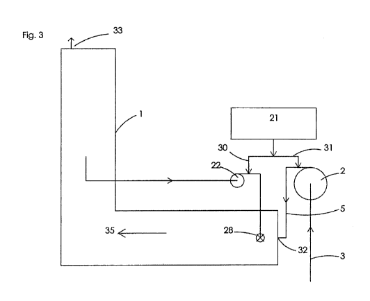
Figure 3 shows an L-shaped ballast tank, seen from the side, see section A
in figure 4, with a nozzle head arranged in relative proximity of the inlet 32
to
the ballast tank.
That means that the location of the nozzle head takes the flow direction in
the
tank into consideration in order to thereby obtain a more efficient treatment
of
the water.
Ballast tanks may be of varying configurations; eg the ballast tanks may be L-
shaped, as shown in figure 3; they may also consist exclusively of a
rectangularly configured tank which may be oriented either vertically or
horizontally.
The number of nozzle heads 28 in a ballast tank 1 may vary in response to
the configuration of the ballast tanks as well as to their size.
The oxygen-containing bubbles that are formed by the injection of the
nitrogen gas via the nozzles will inherently seek upwards in a ballast tank.
Irrespectively of the configuration of a ballast tank, the nozzle heads should
therefore optimally be arranged in the lower zone of the tank.
From figure 3 it will appear that the ballast tank 1 is provided with a valve
33
at the top of the tank, whereby excess gas, if any, may be discharged.
According to one embodiment, the valve 33 may ensure a pressure slightly
above that of the atmosphere in the ballast tank by means of an ongoing
supply of nitrogen to the water in the ballast tank. Thereby it is prevented
that
atmospheric air containing oxygen enters into the ballast tank.
CA 02825409 2013-07-23
WO 2012/116698
PCT/DK2012/050038
12
According to an aspect of the invention, inert gas, nitrogen and/or carbon
dioxide may be supplied to the ballast water in the water supply pipe between
the ballast pump and the ballast tank, on the delivery side, via the
generator.
According to a further aspect of the invention, as illustrated in figure 6,
wherein ballast water is treated while it passes through the ballast tank and
is
thus able to be passed on in treated form to other ballast tanks, it is an
option
to establish several rows of nozzle heads in a ballast tank, wherein each row
is arranged transversally to the flow direction in the ballast tank, and
wherein
the rows are arranged successively after one another in the flow direction.
Thereby a lead front zone of treated ballast water is formed from one row to
the next one, wherein zones of ballast water are treated onwards through the
ballast tank in the flow direction. The front zone which is designated by an
arrow in figures 3 and 4 will thus be essentially at right angles to the flow
direction in the ballast tank.
Such treatment is made even more efficient in having a number of minor
recirculation systems coupled to the same ballast tank 1, see figure 6. For
instance, each row of nozzle heads 28 may constitute a recirculation system,
wherein each row of nozzle heads may treat the ballast water on a
continuous basis through the ballast tank in the flow direction to the effect
that the recirculated water is discharged between the rows of nozzle heads
successively in the flow direction.
Thereby the surrounding ballast water for each row of nozzle heads 28 in the
ballast tank will, in the flow direction, be subject to further treatment in
the
next row of nozzle heads 28.
CA 02825409 2013-07-23
WO 2012/116698
PCT/DK2012/050038
13
Thus each single minor recirculation system will further treat the ballast
water
from the preceding recirculation system which will thereby enhance the
deoxydization in the front zone 35 of the ballast water.
By the system shown in figure 6, the ballast water will contain an amount of
oxygen of eg about 8 ppm before the ballast pump, and, after the supply of
nitrogen, the value may have come down as far as to eg 2 ppm, and by the
continuous treatment through rows of nozzles the content is decreased from
2 ppm to eg 0.8, 0.4, and finally to 0.1 ppm. Thus, the ballast water will
have
a value of 0.1 pmm when the ballast water is passed on to the next ballast
tank.
In case ballast water is treated concurrently in two tanks, and that ballast
water is pumped on to the remaining ballast tanks via the ballast pumps, it is
possible, in that case, to supply further nitrogen during passage from the one
ballast tank to the other.
Figure 4 shows a ballast tank 1 seen from above. In the ballast tank two
nozzle heads 28 are provided. Nitrogen-containing ballast water is advanced
via distribution pipes 26, to branch pipes 27, on to the nozzle heads 28 in
the
ballast tank. The two nozzle heads 28 are arranged in the first portion of the
tank, near the inflow of ballast water to the ballast tank 1 to the effect
that the
treatment process takes place at the inlet 32, and a lead front zone 35 is
formed in the flow direction.
In the treatment of the ballast water and in order to optionally uphold an
oxygen-poor or oxygen-free environment in the ballast water, nitrogen is
added to the ballast tanks for periods of time or at fixed intervals, if
necessary. The supply of nitrogen may take place directly to the ballast water
in the ballast tanks via tubing 31 between nitrogen generator 21 and the
ballast tanks 1 or via the recirculation system 20.
CA 02825409 2013-07-23
WO 2012/116698
PCT/DK2012/050038
14
The periodic supply of nitrogen to the water in the ballast tank may likewise
ensure that atmospheric air containing oxygen does not penetrate into the
ballast tank.
Likewise, according to an embodiment, a device 37 may be integrated into
the recirculation system 20 which is to ensure a convenient treatment with
ozone, UV irradiation or the like, to the effect that it is possible to tailor
the
kind of treatment to a given situation which may occur in the future.
The integrated device may, in one embodiment, comprise a unit that further
sterilises the water by means of heat. In the embodiment shown in figure 7,
the device comprises a heat exchanger 41, such as eg a plate heat
exchanger that exchanges heat between the water running into and out of,
respectively, the device. In the following, such heat exchanger will be
designated: the primary heat exchanger.
Thus, figure 7 shows two feeder lines passing through the primary heat
exchanger. The uppermost feeder line is the line that takes water into the
primary heat exchanger, and, as will appear from the figure, there is, to the
left of the primary heat exchanger 41, a second heat exchanger 40. The
second heat exchanger 40 supplies thermal energy to the water running
through it. Typically that heat comes from the principal engine of the ship
(not
shown), but, of course, the heat may also be supplied from some other
energy source.
From below the second heat exchanger 40 it will appear that the water that
has passed through the second heat exchanger 40 runs through a partial
area 42 before it leaves the device 37 via the bottom feeder line in the
primary heat exchanger 41. The purpose of the partial area 42 is to increase
the time during which the water has a high temperature, ie to increase the
time elapsing from the point when the water leaves the second heat
CA 02825409 2013-07-23
WO 2012/116698
PCT/DK2012/050038
exchanger 40 and until it runs into the primary heat exchanger. Thus, the
partial area will be designated the dwell-time increaser in the following. The
purpose of the dwell-time increaser is to increase the time during which
sterilisation by means of heat takes place. The dwell-time increaser 42 may,
5 in a simple embodiment, merely comprise tubes with an increased diameter,
since the throughput rate in that tube will thereby be decreased. The dwell-
time increaser may also be constituted by a tank/vessel of eg about 0.3 m3.
The capacity of 0.3 m3 was selected on the basis of an example wherein the
10 flow through the heat exchangers is 125 m3/hour. That volume will bring
about a dwell time of about 10 seconds, cf: 125 m3 /3600 s X 10 s = 0.3 m3.
In the shown example the water has, when it leaves the ballast tank, a
temperature of about 20 C. After having passed the circulating pump 22, the
15 water is heated to a temperature of about 80 in the primary heat
exchanger
41, following which it is heated further by about 5 degrees in the second heat
exchanger 40 before it passes through the dwell-time increaser 42. Then the
water leaves the device 37 via the primary heat exchanger. In the shown
example, it takes place at a temperature of about 25 C.
Obviously the dwell time may be varied by changing the flow and/or the
throughput rate, and the about 10 seconds are not always the optimal time
either, but experience has shown that a dwell time of about 10 seconds at 85
C, like in the shown example, has a good sterilising effect.
By including a heat exchanger as shown, the temperature of the water in the
ballast tanks is also raised. The temperature on the outside of the ballast
tanks (on the outside of the vessel) being thereby typically lower than the
heated ballast water, the difference in temperature between the ballast water
and the walls of the ballast tank will contribute to the formation of internal
CA 02825409 2013-07-23
WO 2012/116698
PCT/DK2012/050038
16
circulation patterns in the ballast tanks between the internal structures
thereof. This increases the overall effect of the treatment of the ballast
water.
In the exemplary embodiment explained above, comparatively narrow
temperature intervals and time periods are employed. Of course, the
invention is not restricted to said intervals or temperatures as they can be
varied within the ordinary activities of the person skilled in the art.
A device 37 as described above having two heat exchangers may function
independently in a plant for treating ballast water and is not functionally
dependent on the units and other inventions described in the present
application. Albeit ¨ as explained above ¨ there may be a synergy between
the use of the device and other ones of the described inventions, it is,
however, an option to use it in parallel or in series with any one of the
other
sterilisation methods described and set forth in the present application.
Moreover, the device may operate independently of or in any combination
with the remaining sterilisation methods described and set forth in this
application, and those aspects may be subject to independent applications.
According to a convenient embodiment, the nozzle heads 28 may be
arranged flush with the internal structures/bulkheads 36 of the ballast tank
in
openings 38 in the bulkheads 36 of the ballast tanks as will appear from
figure 5. By that arrangement of the nozzle heads, the bulkheads of the
ballast tanks will hinder as little as possible effective treatment of the
ballast
water, and the propagation of the gas-containing ballast water takes place
most effectively to the effect that the least possible number of possible
rotating nozzle heads can be used.