Note: Descriptions are shown in the official language in which they were submitted.
CA 02826082 2013-07-30
WO 2012/107803
PCT/IB2011/051597
1
DEFORMABLE GUIDE FOR PARTITIONS IN GENERAL
DESCRIPTION
The present patent concerns the field of wall construction with prefabricated
panels applied to a light bearing structure, and in particular it concerns a
new type of section bar for making light bearing structures on which
prefabricated panels can be applied and fixed.
At present metallic structures supporting panels in plasterboard or other
similar materials are widely used for making partitions or furnishing walls.
Said structures are easy and quick to make and allow walls to be obtained
that have special or arched shapes otherwise expensive and difficult to
obtain with bricks and cement.
Rectilinear walls or partitions can be made with plasterboard panels applied
to a frame of rectilinear elements in wood or metal section bars.
If the walls are not rectilinear, deformable guides are used that are
constituted by die cut and bent plate so as to form a continuous assembly of
modular box-shaped elements.
A plate strip is substantially die cut and bent in the shape of a U so as to
form a series of U-shaped segments joined to one another by three
projections, two on the sides and one on the bottom. Successively, the
projections are bent inside the "U" shape until obtaining a series of box-
shaped elements without one of the large surfaces and joined to one another
through portions of the small surfaces.
In the construction stage each deformable guide is used as it is or is adapted
to the curvilinear shape to be obtained, by unfolding the bent projections.
Said deformable guides, however, pose a series of drawbacks:
CA 02826082 2013-07-30
WO 2012/107803
PCT/IB2011/051597
2
- the limited width of the U-shaped elements makes them incompatible with
most of the similar but rectilinear structures that must converge in the
curved portions and be integrated with them, without complex and
precarious adaptations;
- the presence of the projections bent inwards prevents the longitudinal
sliding movement in the correct position of the vertical upright plate section
bars that make up the supporting frame of the panels in plasterboard or
similar materials;
- the presence of the projections bent inwards makes it impossible to use
them as a seat for a recessed sliding door;
- the risk that the fixing screws of the plasterboard or external objects
or
structures may correspond to the die cut holes present in the articulated
element makes said fixing insecure.
To remedy all the above mentioned drawbacks a new type of deformable
guide has been designed and constructed.
The new deformable guide is made up of a plate strip that is die cut and bent
so as to take the form of a U-shaped profile.
The metal strip is die cut and holed so as to obtain continuous sections
alternating with sections having cuts and holes.
Each section with cuts and holes is provided with cuts on the side bands and
the centre band.
In particular:
- each side band is provided with three cuts parallel to one
another and
perpendicular to the edge of the strip;
- the centre area is provided with two cuts, parallel to each other and
CA 02826082 2013-07-30
WO 2012/107803
PCT/IB2011/051597
3
aligned with the external cuts present on the side bands;
- two holes with five sides, of which three sides are orthogonal to one
another and arranged in the area included between the side bands
and the centre band, while two sides are inclined with respect to each
other and to the other sides with the vertex included between them
facing towards the centre of the centre area.
The side bands or edges of the strip are then bent orthogonally to the centre
band or area of the strip so as to form a section bar with U-shaped profile.
Consequently, the portion of each five-sided hole having three orthogonal
sides comes to be positioned in the side wall of the U-shaped section while
the other portion with angled vertex of each hole comes to be positioned in
the centre bottom wall of said U-shaped profile of the section bar.
The areas with cuts are pre-bent towards the inside of the "U" shape, so that
each portion included between two parallel cuts, both of the side walls and
of the bottom wall of the U-shaped profile, faces towards the inside of the
U-shaped profile of the section bar.
In particular, said areas with cuts are pre-bent towards the inside of the "U"
shape so that the portions included between two parallel cuts form a 115
angle.
The deformable guide made up as described makes it possible to obtain,
with the aid of plasterboard panels, linear or arched walls or false ceilings.
The new deformable guide is used as it is for linear structures. It can serve
as a guide for a sliding door or a recessed door inside the wall made with the
new deformable guide and plasterboard panels.
If it is necessary to make partitions, walls, false ceilings or other curved
CA 02826082 2013-07-30
WO 2012/107803
PCT/IB2011/051597
4
structures it is possible to shape the new deformable guide by properly
bending the portions provided with cuts. The new deformable guide can be
curved both laterally, so that the base of the U-shaped profile always lies on
one plane, and vertically, so that all the wings of the U-shaped profile of
the
structural elements lie on two parallel planes.
In any case, when fixing elements such as screws or bolts are applied, there
is always a portion of the wall of the new deformable guide that guarantees
suitable and adequate resistance.
Furthermore, during assembly, the new deformable guide makes it possible
to lay easily and quickly the upright section bars in galvanized steel that
make up the supporting frame of the panels in plasterboard or similar
materials and to slide said upright section bars until reaching the fixing
point.
Therefore, the new deformable guide considerably simplifies the assembly
operations, thus reducing the time needed for the installation of the walls
and false ceilings produced in this way.
The attached drawing shows, by way of non-limiting example, a practical
embodiment of the invention.
Figure 1 shows the development of the new deformable guide, that is, the
die cut plate strip before bending.
The metal strip is provided with areas (X) without gaps alternating to areas
(Y) with cuts and die cuts.
The folding lines (Si, S2) are indicated by dash-point lines.
The plate strip comprises a centre band (A) and two side bands or edges (B).
Each side band (B), with respect to the area (Y) with cuts, is provided with
CA 02826082 2013-07-30
WO 2012/107803
PCT/IB2011/051597
three cuts (C) that are parallel to one another and perpendicular to the edge
of the plate strip.
Each centre band (A), with respect to the area (Y) with cuts, is provided
with two cuts (D) that are parallel to each other and aligned with the
5 external cuts (C) present on the side bands (B).
There are two holes (E) with five sides, of which three sides are orthogonal
to one another and arranged in the area included between the side bands (B)
and the centre band (A), and two sides are inclined with respect to each
other and to the other sides with the vertex included between them facing
towards the centre of the central area (A).
The strip is then bent along the folding lines (Si, S2) forming a U-shaped
section bar.
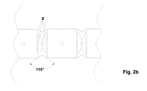
Figures 2a and 2b show a side view and a top view of the new section bar
formed by the centre band (A) and the side bands (B) bent so as to form a
U-shaped profile.
The areas (Y) with cuts (C, D, E) are pre-bent towards the inside of the "U"
shape, so that each portion (Z) included between two parallel cuts (C, D),
both of the side walls (B) and of the bottom wall (A) of the U-shaped
profile, faces towards the inside of the U-shaped profile of the section bar.
In particular, said areas (Y) with cuts (C, D, E) are pre-bent towards the
inside of the "U" shape so that the portions (Z) included between two
parallel cuts (C, D) form a 115 angle.
Therefore, with reference to the above description and the attached drawing,
the following claims are expressed.