Note: Descriptions are shown in the official language in which they were submitted.
CA 02826083 2013-07-30
WO 2012/106053
PCT/US2012/000057
1
SENSOR ASSEMBLY FOR HYGENIC MATERIAL PROCESSING SYSTEMS
Technical Field.
This invention relates to sensor assemblies for use in automated process
control
systems, and particularly to such sensor assemblies with improved reliability
and
functionality for use in hygienic material processing systems.
Background Art.
Automated process control systems are conventionally used in various
industries,
such as biotechnology, beverage, dairy, food, and pharmaceutical
manufacturing. These
systems rely upon the measurement of process parameters (pressure,
temperature, flow
rate, fluid level, etc.) which are sensed by sensor assemblies. These sensor
assemblies
not only sense the particular process parameter desired at that particular
point in the
process, but also transmit the sensed values of the parameter to the automated
process
control system for appropriate action by the control system. That is, the
sensor
assemblies typically have both a sensing function and a communications
function. Prior
art sensor assemblies are conventionally single integrated units (i.e.,
includes the sensor
function and the communications/signal processing in a single physical
housing). With
conventional prior art sensor assemblies, the entire assembly must be replaced
when the
sensing portion fails.
The housing for conventional sensor assemblies vary widely depending upon
various factors, including (1) type of process connection, (2) parameter range
for operation,
(3) signal output (e.g., 4-20ma, digital or field bus), and (4) orientation of
installation.
Although it is possible to keep a complete inventory of the sensor assemblies
needed to
keep the process line functioning, that can be an expensive proposition which
some
industries typically forgo. For example, the dairy facilities frequently do
not stock a
complete inventory of sensor assemblies. If the proper sensor assembly is not
available,
for whatever reason, when an installed assembly fails, production must be shut
down until
the proper sensor assembly is obtained and installed. This can be an expensive
inconvenience for companies located near sources of replacement sensor
assemblies. It
. can become an even more serious inconvenience when the plant is located in
remote
areas or in emerging countries with limited infrastructure.
One possible solution is to replace only the sensing portion of the assembly,
since
that is the portion that typically fails. That would drastically reduce the
inventory that
CA 02826083 2013-07-30
WO 2012/106053
PCT/US2012/000057
2
would be required to maintain full production. But this presents a problem:
how to
calibrate the sensor assembly in the field. As noted above, the sensor
assembly includes
both a sensing function and a communication function. Calibration of the
sensor
assembly involves ensuring not only that the sensing portion is supplying
signals at the
desired levels for the particular process parameter value being measured, but
also that
the communication part of the sensor assembly properly recognizes the output
of the
sensing portion and accurately communications the proper value of the proper
parameter
to the automated process control system. Such calibration in the field can be
difficult.
Since field calibration is not a common occurrence, it is prone to error if
attempted by a
local technician who typically lacks the needed expertise and can be a cause
of further
delay and expense if done by a specialist, who typically must travel to the
processing
facility to effect the replacement.
In many industries, e.g., dairy or brewing, sensor assemblies are subjected to
high
levels of humidity and moisture in general. This operating environment can
also be true
for tropical locales, even for typically "dry" material processing systems.
The electronics in
sensor assemblies can be extremely sensitive to unwanted moisture. Unwanted
moisture
can enter existing sensor assemblies (and potentially damage the electronics)
not only in
high humidity conditions, but also when the housing for the assembly is dented
or
otherwise damaged in such a way as to interfere with any moisture seals which
are built
into the sensor assembly. Existing sensor assemblies typically have visual
displays
incorporated into the assembly for displaying to a user the value of the
particular
parameter being measured. These displays are typically seen through a
transparent
cover. In high humidity conditions, this cover can accumulate moisture,
thereby obscuring
the view of the visual display in conventional sensor assemblies. The
transparent
enclosure, of course, must also be attached to the sensor assembly housing in
such a
way as to prevent the passage of moisture to the interior of the housing, but
this goal is
not always satisfactorily achieved with existing sensor assemblies. Frequently
it is not
possible for the person installing the transparent cover to determine whether
the cover has
been properly installed on the sensor assembly housing or to determine whether
a
moisture-tight seal has been achieved.
Summary of the Invention.
Among the various objects and features of the present invention may be noted
the
provision of an improved sensor assembly which provides for easy sensor
replacement.
CA 02826083 2013-07-30
WO 2012/106053
PCT/US2012/000057
3
Another object is the provision of a sensor assembly with an auto-calibrated
output.
A third object is the provision of such a sensor assembly which simplifies
inventory
and supply chain problems.
A fourth object is the provision of such a sensor assembly which is less
complex to
install, use and maintain.
A fifth object is the provision of such a sensor assembly which is
particularly suited
for hygienic processing environments such as food, dairy, brewery and pharma.
A sixth object is the provision of such a sensor assembly which reduces the
risk of
moisture ingression due to physical damage to sensor assembly sealing
surfaces.
A seventh object is the provision of such a sensor assembly which minimizes
the
risk of moisture or other contamination accumulating on the transparent cover
of the
assembly.
An eighth object is the provision of such a sensor assembly which provides a
positive indication such as a tactile or a visual indication when the seals
between the
transparent cover and the housing are properly seated.
A ninth object is the provision of such a sensor assembly which provides
redundant
sealing against moisture ingression with two different failure modes.
Other objects and features will be in part apparent and in part pointed out
herein.
In a first aspect of the present invention, a sensor assembly for use in an
automated process control system includes a replaceable sensor module, an
assembly
housing containing an assembly housing processor and an electrical connector
connected
to the processor and accessible by the automated process control system. The
replaceable sensor module includes an enclosure adapted to be mounted in a
position to
sense a process variable, a process variable transducer positioned in the
enclosure so as
to be exposed to the process variable, and a non-volatile memory having stored
therein
specific profiling data for the sensor module. The assembly housing processor
in the
assembly housing has data representing a desired sensor assembly output
characteristic,
and is responsive to receipt of the specific profiling data and to the data
representing the
desired sensor assembly output characteristic to calibrate the sensor assembly
to provide
the desired sensor assembly output characteristic when connected to the sensor
module
having the specified profiling data.
In a second aspect of the present invention, a sensor assembly includes a
replaceable sensor module containing at least one transducer and at least one
electronic
circuit connected to the transducer, and an assembly housing containing at
least an
CA 02826083 2013-07-30
WO 2012/106053
PCT/US2012/000057
4
assembly housing processor and an electrical connector connected to the
processor. The
assembly housing has a cover secured thereto, and also has an opening for
accepting a
plug body through which passes at least one electrical connector. The assembly
housing
has at least two paths for migration of moisture from the exterior of the
assembly housing
to the interior of the assembly housing. At least one axial seal is positioned
along a first of
the moisture migration paths to resist the passage of moisture from the
exterior of the
assembly housing to the interior of the assembly housing. At least one radial
seal is also
positioned along the first moisture migration path to resist the passage of
moisture from
the exterior of the assembly housing to the interior of the assembly housing.
In a third aspect of the present invention a method of operating a sensor
assembly
in a hygienic material processing system includes sensing a process variable
using at
least one transducer and at least one electronic circuit connected to the
transducer,
periodically automatically testing an electrical characteristic of the
transducer, the testing
occurring at a time other than when the process variable is being sensed,
providing at
least one threshold for the value of said electrical characteristic, and
indicating when the
electrical characteristic has gone over the threshold.
In a fourth aspect of the present invention, a sensor assembly for use in an
automated process control for a hygienic material processing system includes a
two-wire
current loop communications link communicating sensor data to the automated
process
control. The current in the loop corresponds to the measured value of the
process
variable. Feedback from the current loop is used to control the magnitude of
the current
and to generate a display of the loop current for the user.
Brief Description of the Drawings
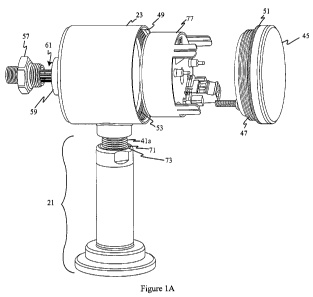
Fig. 1 is a front elevation of the sensor assembly of the present invention;
Fig. 1A is an exploded view of the sensor assembly of Fig. 1;
Fig. 1B is an exploded view like Fig. 1A with parts broken away for clarity;
Fig. 2 is a diagrammatic view illustrating the use of the sensor assembly of
the
present invention;
Fig. 3 is a block-diagram illustrating various electronic components contained
in the
sensor assembly of Fig. 1;
Fig. 3A is a schematic illustrating the transmitting/current measuring portion
of the
present invention;
CA 02826083 2013-07-30
WO 2012/106053
PCT/US2012/000057
Fig. 4 illustrates the data structure of profiling data stored in the sensor
assembly,
and more particularly in the sensor module portion of the sensor assembly;
Fig. 5 is an exploded view with parts broken away of the mechanical connection
of
one portion of the sensor assembly to the main housing of the assembly;
5 Fig. 5A is an exploded view like Fig. 5 with additional parts broken
away for clarity,
illustrating an axial and radial sealing feature of the present invention;
Fig. 6 is an exploded view of the sensor assembly with parts broken away to
illustrate additional axial and radial sealing features of the present
invention.
Similar reference characters indicate similar parts throughout the several
views of
the drawings.
Best Modes for Carrying Out the Invention
Turning to the drawings, a sensor assembly 11 of the present invention is
shown in
Fig. 1. A partially exploded view is shown if Fig. 1A. Assembly 11 is designed
for use in
the automated process control for a hygienic material processing system 13 as
illustrated
in Fig. 2. In Fig. 2, assembly 11 is shown mounted in a position to sense the
value of a
process parameter (such as pressure of a fluid F) flowing in a pipe P.
Assembly 11
communicates the value of the parameter via any standard communication
protocol to a
process controller 15 having a number of inputs and outputs 17 to control the
process in a
conventional manner. The present invention is not limited to any particular
process
control system, and is instead directed to assembly 11 for use in any such
system. The
process parameter is described herein as being the pressure of the liquid or
other flowable
material being processed, but could also be the level and/or the flow rate of
the liquid and
flowable material.
Turning back to Figs. 1 and 1A, sensor assembly 11 includes a replaceable
sensor
module 21 and an assembly housing 23. Assembly housing 23 contains (see Fig.
3) an
assembly housing processor (micro-controller) 25 and a loop transmitter and
power supply
circuit 27 connected to the assembly housing processor 25 and accessible by
automated
process control system 13. Two wire transmitter systems are well-known in
process
control systems. The transmitter and power supply 27 is connected to the loop
(indicated
by LOOP+ and LOOP- in the lower right-hand corner of Fig. 3) and is powered by
the loop
current flowing through the current loop. In fact, all the electronics of
sensor assembly 11
are ultimately powered by the current from the current loop. The magnitude of
the loop
current is varied by loop transmitter and power supply 27 as a function of the
magnitude of
CA 02826083 2013-07-30
WO 2012/106053
PCT/US2012/000057
6
the process parameter variable being measured. Thus, the loop current is held
at
essentially a constant current value corresponding to the value of the
parameter being
measured, while at the same time all the needs of the circuitry in sensor
assembly 11 are
being supplied from the same current. This latter load is, of course variable,
so the
present invention requires monitoring of the loop current to ensure that it
stays at the
constant current value representing the measured parameter value despite the
changing
amount of current needed by the electronics in sensor assembly 11.
Turning to Fig. 3A, loop transmitter and power supply 27 is shown in more
detail, as
including a power supply portion 27A and a negative feedback control circuit
portion 27B.
Power supply portion 27A supplies regulated power at a desired level to the
rest of the
circuitry of sensor assembly 11. For example, to supply regulated power at
3.3V, power
supply portion 27A may include an output voltage regulator such as the type
sold under
the trade designation LTC3632 and a linear regulator such as the type sold
under the
trade designation TPS77033. Of course, any number of different such components
could
be used, and the particular type of components making up power supply portion
27A is not
considered to be part of the present invention.
The loop current IL flows between the terminals of the loop, labeled Loop+ and
Loop- as indicated in Fig. 3A. The magnitude of that current is governed by
NPN
transistor U2, which may preferably be that sold under the trade designation
BCP55. The
collector of transistor U2 is connected to current loop terminal Loop+, while
the emitter is
connected through a feedback resistor R9 to the other loop terminal Loop-. The
voltage
drop across resistor R9 is supplied to a conventional feedback control circuit
which
constitutes the transmitter portion 27A of the circuitry. This feedback
control circuit uses
the voltage drop across resistor R9, which is a direct measure of the current
flowing in the
loop and an input representing the value of measured process variable, and
supplies a
corresponding signal to the base of transistor U2 (Fig. 3A) The feedback
control circuit is
conventional in construction. For example, it can preferably be configured
using an
amplifier sold under the trade designation 0PA4379. The precise details of
such
feedback circuits and their use in transmitting data over two-wire current
loops are well-
known and are not considered to be part of the present invention.
The feedback signal is preferably also supplied to an internal current meter
27C of
the present invention. More specifically, the feedback signal is measured
using an
analog-to-digital converter (ADC). Such an ADC may be present in many
available ASIC
chips. For example, the ASIC chip sold under the trade designation ZMD31050
has a
CA 02826083 2013-07-30
WO 2012/106053
PCT/US2012/000057
7
built-in ADC which is suitable for this task. The ASIC (or alternatively,
micro-controller 25)
uses this converted digital value to compute the actual loop current. More
specifically, the
processor in the ASIC or the micro-controller itself uses an equation to
compute the actual
current value corresponding to the measured value of the feedback signal. A
first order
linear equation has been found to adequate for this task, although higher
order equations
could also be used. The current loop value, after it is calculated is then
displayed on a
suitable display such as display 28. The 4x7-CHAR LED display shown in Fig. 3
may be
used for display 28, or other suitable display may be provided.
Turning back to Fig. 1, replaceable sensor module 21 includes an enclosure or
housing 29 (Fig. 1) adapted to be mounted in a position to sense the process
variable. A
process variable transducer 31 is positioned in enclosure 29 so as to be
exposed to the
process variable. A non-volatile memory 33 (shown as an EEPROM) is also
disposed in
sensor module 21 and has stored therein specific profiling data for the sensor
module.
More specifically (see Fig. 4), EEPROM 33 has stored therein the pressure-
temperature
characteristics for that particular sensor module 21. That is, the contents of
EEPROM 33
vary from sensor module to sensor module as a function of the particular
transducer 31
contained in the sensor module. As shown in Fig. 4, the profiling data
preferably includes
data taken at three different gain levels (Low, Mid, and High) at multiple
different points
across its range.
Turning back to Fig. 3, it is preferred that sensor module 21 include its own
processor 37 (which in Fig. 3 is an ASIC chip) which is connected to pressure
transducer
31 and to EEPROM 33. ASIC 37 includes and analog-to-digital converter (ADC) to
convert the output of the process parameter transducer 31 to digital values.
It is these
ADC values which constitute the recorded profiling data indicated in Fig. 4.
As a result, it
should be noted that the profiling data stored is a function not only of the
particular
transducer in the sensor module, but also of the particular ASIC chip.
As shown in Fig. 3, transducer 31 (not shown) using a bridge 39 to sense the
process parameter (in this example, pressure). That transducer includes a
strain gage
mounted on a diaphragm, which is described below. In addition, a temperature
transducer
41 is included in transducer 31 for supplying temperature information to ASIC
37. It
should be understood that the present invention is not limited to the use of
any particular
type of sensor for sensing the desired process parameter. Although at present
ASIC 37 is
contemplated as being a CMOS integrated circuit chip sold under the trade
designation
ZMD31050, it should also be understood that any ASIC capable of performing
these
CA 02826083 2013-07-30
WO 2012/106053
PCT/US2012/000057
8
functions could be used. This particular chip is useful since it has the
ability to test the
lumped resistance of the bridge 39 under programmed control. This chip is
designed to
electrically short across the bridge (which effectively cancels the load on
the sensor) and
measure the lumped resistance (common mode voltage) of the bridge. ASIC 37 is
programmed to measure this electrical characteristic of the transducer
periodically
between actual process readings. In addition, high (upper) and low (lower)
thresholds are
set in ASIC 37 so that measurements outside the thresholds are identified.
This state can
be indicated either electrically, visually, or both. This feature allows drift
of the sensor due
to age, adverse conditions, etc. to be detected so that the system can be
recalibrated.
Note that EEPROM 33 is connected to both ASIC 37 and the housing processor 25.
Specifically, sensor module 21 is connected to micro-controller 25 by an i2c
communication bus (although the particular communications protocol is not a
feature of
this invention). The profiling information from the EEPROM is supplied to ASIC
37 so that
the digital output of ASIC 37 to housing processor 25 preferably provides
fully calibrated
digital sensor readings. The information is also supplied to the housing
processor.
Housing processor 25 is responsive to this information to generate a
calibration curve (by
way of example, a third order calibration curve) which it supplies to ASIC 37.
Housing
processor 25 is also responsive to this information and to its own data
representing the
desired sensor assembly output characteristics for that particular sensor
assembly to
provide the desired sensor assembly output characteristic when connected to
the sensor
module having the specified profiling data. In this way, sensor module 21 can
be used
with any number of different assembly housing 23 to provide the correct output
for that
particular sensor assembly at that particular location. This significantly
reduces the
necessary inventory of sensor modules.
Turning back to Fig. 1A it can be seen that sensor module 21 includes a screw
thread 41a by which the sensor module 21 is secured to a mating surface in
assembly
housing 23 to secure the sensor module and the assembly housing into a single
unitary
structure. It is preferred that the sensor module and the assembly housing be
capable of
being secured together by hand, without the use of hand tools. Alternatively,
the sensor
module 21 may be secured to assembly housing 23 by corresponding bayonet-
connector
type structures, which are well known in the art. In the later case,
mechanical connection
of the sensor module to the assembly housing automatically provides the
required
electrical connection therebetween. Bayonet-type electrical connectors are
well known.
CA 02826083 2013-07-30
WO 2012/106053
PCT/US2012/000057
9
Other connectors such as push-pull electrical connectors such as those sold by
LEMO S.A.
may also be used to provide simultaneous electrical and mechanical connection.
As shown in Fig. 1A, sensor assembly 11 includes a transparent cover 45 with
screw threads 47 which together with mating threads 49 on the interior of
assembly
housing 23 permit the cover to be attached to the assembly housing. The
attachment of
cover 45 to assembly housing 23 potential creates a path for migration of
moisture from
the exterior of the assembly housing to the interior of assembly housing 23.
For this
reason, an o-ring 51 is disposed on cover 45 and a second o-ring 53 is
disposed in
assembly housing 23. (In Fig. 1B, various parts have been removed to more
clearly show
the o-rings.) When cover 45 is properly screwed onto assembly housing 23, both
o-ring 51
and o-ring 53 provide moisture-resistant seals between the cover and the
assembly
housing. Note as well that attaching cover 45 to assembly housing 23 causes o-
ring 51 to
be axially compressed, while that same action causes o-ring 53 to be radially
compressed.
Each of these seals, therefore, provides an independent seal, with different
modes of
failure, thereby maximizing the possibility of preventing moisture from
entering the interior
of assembly housing 23. 0-ring 51 is positioned such that when the cover is
properly
sealed to assembly housing 23 that fact can be visually verified. It is also
preferred that
both o-rings provide a suitable tactile sensation when cover 45 is properly
sealed to
assembly housing 23.
Also shown in Figs. 1A and 1B are a threaded plug 57 for attachment to a
corresponding threaded sleeve 59 (Fig. 1A only) of assembly housing 23. The
electrical
connector 61 for making connection between the micro-controller 25 and the
process
controller 15 extends through plug 57. Threaded sleeve 59 potentially creates
a second
path for migration of moisture into the assembly. As can be seen in Fig. 5 and
5A, a pair
of o-rings 63 and 65 are disposed between plug 57 and mating sleeve 59 to
provide axial
and radial seals to prevent such a migration of moisture into the assembly.
The connection between sensor module 21 and assembly housing 23 also provides
a potential path for moisture migration into the assembly housing. A pair of o-
rings 71, 73
(Figs. 1A, 1B, and 6) are disposed in such a manner as to provide axial and
radial seals
such as described above in connection with the other two migration paths.
Also shown in Figs. 1A and 1B is a block 77 which includes the various
electronic
components contained within assembly housing 23. Securing cover 45, plug 57,
and
sensor module 21 to the assembly housing 23 as described above provides a
redundant,
moisture resistant seal for the entire assembly housing. Note that many of the
seals are
CA 02826083 2013-07-30
WO 2012/106053
PCT/US2012/000057
coaxial. However, the seals formed by o-rings 71 and 73, while coaxial to each
other, are
positioned transversely relative to the position of the seals formed by the
other o-rings.
The seals formed by sensor module o-rings 61 form seals which are adjacent
each other.
This is also true of o-rings 71 and 73. The o-rings 51 and 53 which form the
seals for
5 cover 45 are more widely spaced apart, but they still provide both axial
and radial sealing.
In view of the above, it will be seen that the various objects and features of
the
present invention are achieved and other advantageous results obtained.
Nothing in this
description should be construed in a limiting sense.