Note: Descriptions are shown in the official language in which they were submitted.
CA 02826358 2013-08-01
WO 2012/113697
PCT/EP2012/052654
1
Needle Adapter
Description
Technical Field
The invention relates to a needle adapter for coupling a needle to an
injection device.
Background of the Invention
Conventionally, single-use needle assemblies are provided for use with
injection
devices, e.g., insulin pens. The needle assemblies generally include a needle
assembly
integrally formed with a double-sided needle and include a means (e.g.,
threads,
friction) for detachably coupling to a distal end of the injection device.
After use, the
needle assembly is removed from the injection device and discarded.
Many needle assemblies are relatively large and become difficult to package
and carry.
Further, it would be more cost-effective to use replaceable needles rather
than larger,
more expensive needle assemblies. Thus, there exists a need for a more
efficient
needle assembly configuration.
Summary of the Invention
It is an object of the present invention to provide an improved needle adapter
for
coupling a needle and an injection device. In an exemplary embodiment, the
needle
adapter is sized and shaped to be coupled to a variety of injection devices,
e.g., insulin
pens. For example, the needle adapter may be sized and shaped like a Type A
needle
assembly. As understood by those of skill in the art, such a needle adapter
may allow
legacy injection devices to support the use of single-use needles, which may
be more
economical, more efficient and easier to use than single-use needle
assemblies.
CA 02826358 2013-08-01
WO 2012/113697
PCT/EP2012/052654
2
The exemplary embodiments of the present invention describe a needle adapter
for
coupling a needle to an injection device. The needle adapter may comprise a
proximal
portion for receiving a distal end of the injection device, and a distal
portion having an
opening for receiving the needle.
The proximal portion of the needle adapter may have a screw thread on an inner
surface, e.g., for engaging a corresponding screw thread on the injection
device. The
needle adapter may include a longitudinal needle guide formed along a central
axis of
the needle adapter for receiving the needle. A retaining element may be formed
along a
portion of the needle guide for receiving a retaining member formed on the
needle. A
diameter of the retaining element may be larger than a diameter of the needle
guide. A
proximal end of the retaining element may prevent proximal displacement of the
retaining member in the needle guide beyond the retaining element. A tactile
feedback
may be provided when the retaining member is received within the retaining
element.
The retaining member may be conically shaped, narrowing in a proximal
direction, and
the opening in the distal portion of the needle adapter may be conically
shaped,
narrowing in the proximal direction. At least one radial slot may be formed in
the distal
portion, wherein at least one end of each of the at least one radial slots
terminates at
the opening. The at least one radial slot may form at least one latch, which
may prevent
distal displacement of the retaining member in the needle guide beyond the
retaining
element.
Further scope of applicability of the present invention will become apparent
from the
detailed description given hereinafter. However, it should be understood that
the
detailed description and specific examples, while indicating preferred
embodiments of
the invention, are given by way of illustration only, since various changes
and
modifications within the spirit and scope of the invention will become
apparent to those
skilled in the art from this detailed description.
Brief Description of the Drawings
CA 02826358 2013-08-01
WO 2012/113697
PCT/EP2012/052654
3
The present invention will become more fully understood from the detailed
description
given hereinbelow and the accompanying drawings which are given by way of
illustration only, and thus, do not limit the present invention, and wherein:
Figure 1 shows a perspective view of an exemplary embodiment of a needle
adapter coupled to an injection device according to the present
invention,
Figure 2 shows a sectional view of an exemplary embodiment of a needle
adapter coupled to an injection device according to the present
invention;
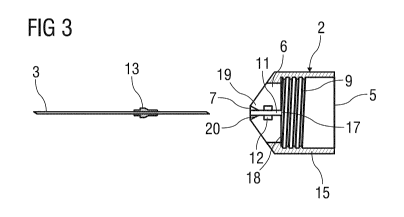
Figure 3 shows an exploded sectional view of an exemplary embodiment of a
needle adapter and a corresponding needle according to the present
invention;
Figure 4 shows an exemplary embodiment of a needle adapter and a
corresponding needle according to the present invention; and
Figure 5 shows an exemplary embodiment of a removal device for a needle
according to the present invention.
Corresponding parts are marked with the same reference symbols in all figures.
Detailed Description of Preferred Embodiments
Figures 1 and 2 show a perspective view and a sectional view, respectively, of
an
exemplary embodiment of an injection device assembly 1 with a needle adapter 2
coupling a needle 3 (e.g., a double-sided/tipped needle) to an injection
device 4. The
injection device 4 may be designed as, for example, a cartridge holder for a
cartridge
containing a medicament.
CA 02826358 2013-08-01
WO 2012/113697
PCT/EP2012/052654
4
Figure 3 shows an exploded sectional view of the needle adapter 2 and the
needle 3
shown in Figures 1 and 2.
In an exemplary embodiment, the needle adapter 2 may have a proximal portion 5
that
is shaped to removably engage a distal end of the injection device 4,
cartridge holder or
adapter attached thereto. For example, the proximal portion 5 may have the
shape of a
hollow cylinder with an open proximal end which is shaped and sized to receive
the
distal end of the injection device 4. A distal end 6 of the needle adapter 2
may include
an opening 7 suited for receiving the needle 3.
In an exemplary embodiment, the distal end 6 may have a conical shape tapering
from
a proximal cylindrical portion 15 of the needle adapter 2 to the opening 7 in
the distal
end 6. Furthermore, the distal end 6 may comprise one or more slots 8
extending
radially from the opening 7. The slots 8 may form one or more latches 9.
In an exemplary embodiment, an inner diameter of a proximal portion 15 of the
needle
adapter 2 may correspond to an outer diameter of a distal end 16 of the
injection
device 4. The needle adapter 2 may comprise a screw thread formed as an
internal
thread 9 on an inner surface of the cylindrical portion 15 of the needle
adapter 2. The
injection device 4 may comprise a corresponding external thread 10 formed on
an outer
surface of the distal end 16. The internal thread 9 and the external thread 10
may
provide a mechanism for removably mounting the needle adapter 2 on the
injection
device 4. Those of skill in the art will understand that other mounting
mechanisms such
as, for example, snap-fit, bayonet-fit, frictional fits, etc., may be used for
mounting the
needle adapter 2 on the injection device 4.
The needle adapter 2 further comprises a needle guide 11 for receiving the
needle 3. In
an exemplary embodiment, the needle guide 11 may be a longitudinal channel
formed
along a central axis of the needle adapter 2 terminating distally at the
opening 7 and
proximally at a proximal opening 17 formed in a proximal surface 18 of the
needle
adapter 2 which abuts a distal surface of the injection device 4.
CA 02826358 2013-08-01
WO 2012/113697
PCT/EP2012/052654
Formed along a portion of the needle guide 11 may be a retaining element 12
for
engaging a retainer member 13 formed (e.g., overmolded) on the needle 3. In an
exemplary embodiment, the retaining element 12 may be an annular cut-out
formed
5 along a portion of the needle guide 11 which has a larger diameter than
the needle
guide 11. The diameter or space occupied by the retaining element 12 may
correspond
to a size and shape of the retainer member 13 on the needle 3. After the
needle
adapter 2 is coupled to the injection device 4, the needle 3 can be coupled to
the needle
adapter 2 by inserting the needle 3 into the needle guide 11. There may be a
tactile
feedback provided in that resistance will be encountered when moving the
needle 3
proximally through the needle guide 11 until the retaining member 13 reaches
the
retaining element 12, at which point a user will feel a release of the
resistance.
Preferably the retaining element 12 has a proximal portion (e.g.,
surface/wall) which
prevents further proximal movement of the needle 3 in the needle guide 11.
When the
needle 3 has been inserted into the needle adapter 2 such that the retaining
member 13
is located in the retaining element 12, a proximal tip of the needle 3 will
have been
inserted into a medicament cartridge in the injection device 4.
The opening 7 at the distal end of the needle adapter 2 may be configured to
facilitate
insertion (and/or removal) of the needle 3. In an exemplary embodiment, the
opening 7
may comprise a conically shaped inner surface 20 narrowing in the proximal
direction.
In this exemplary embodiment, the retaining member 13 on the needle 2 may be
conically (or frusto-conically) shaped, and narrowing in a proximal direction,
to engage
the opening 7. The corresponding shapes and sizes of the inner surface 20 of
the
opening 7 and the retaining member 13 may allow the user to properly align the
needle
3 with needle guide 11.
When the needle 3 is inserted into the needle guide 11, an outer surface of
the retaining
member 13 may engage and inner surface 20 of the opening 7, and as the needle
3 is
advanced proximally, the latches 19 may bend proximally. When a distal end of
the
retaining member 13 passes the latches 19, the retaining member 13 will be
secured in
the retaining element 12. The latch 19 may be formed to prevent distal
displacement of
CA 02826358 2013-08-01
WO 2012/113697
PCT/EP2012/052654
6
the needle 3 when the retaining member 13 has been secured in the retaining
element
12, and a proximal surface of the retaining element 12 may be formed to
prevent
proximal displacement of the needle 3.
After the retaining member 13 has been secured in the retaining element 12,
there
should be a sufficient length of the needle 3 proximal to the retaining member
13 that
would allow a proximal tip of the needle 3 to enter the medicament cartridge.
Figures 4a and 4b show another exemplary embodiment of a needle adapter 40
coupling a needle 41 to an injection device 42. The needle 41 may be a double-
sided
needle including proximal and distal tips. The proximal tip of the needle may
be
inserted into a cartridge 43 in the injection device 42 which contains a
medicament, and
the distal tip may be used to pierce a patient's skin for delivery of the
medicament.
The needle 41 may include a retaining member 44 sized and shaped to fit within
a
retaining element 45 formed in the needle adapter 40. The needle 41 may
further
include a removal member 46 which may be used to remove the needle 41 from the
needle adapter 40. The retaining member 44 and/or the removal member 46 may be
formed as one or more overmolded portions on the needle 41. In an exemplary
embodiment, the retaining member 44 may be formed as a sphere and the removal
member 46 may be formed as a disc or inverted cross.
To couple the needle 41 to the needle adapter 40, the needle 41 may be
inserted into
an opening 47 formed in a distal end of the needle adapter 40. Preferably a
diameter or
cross-section of the retaining member 44 is larger than a diameter or cross-
section of
the opening 47. However, the distal end of the needle adapter 40 may comprise
a
plurality of arms 48 which may be formed by slots (not shown) created in the
distal end.
That is, the distal end of the needle adapter 40 may be a solid, conical
piece, and one
or more slots may be formed in the conical piece to create the arms 48. When
the
retaining member 44 is pushed proximally into the opening 47, the arms 48 may
move
from a first position radially outward to a second position to allow the
retaining member
44 to pass through to the retaining element 45. When the retaining member 44
is
CA 02826358 2013-08-01
WO 2012/113697
PCT/EP2012/052654
7
secured within the retaining element 45, the arms 48 may return to the first
position,
ensuring that the needle 41 maintains its position relative to the needle
adapter 40.
When the retaining member 44 is secured within the retaining element 45, the
proximal
tip of the needle is located within the cartridge 43, and the injection device
42 may be
ready to deliver an injection.
Figure 5 shows an exemplary embodiment of the needle adapter 40 and a needle
removal device 50. In an exemplary embodiment, the removal device 50 may be a
container 51 with a removal mechanism 52 formed integrally with the container
51, such
that when the needle 41 is removed from the needle adapter 40, the needle 41
is
permanently stored in the container 51.
In an exemplary embodiment, the removal mechanism 52 may include an opening 53
which is sized and shaped to receive a distal end of the injection device 42,
the needle
41 and the needle adapter 40. A depth of the opening 53 may be varied. For
example,
the opening 53 may be relatively shallow, sized to receive the needle 41 and
needle
adapter 40. Alternatively, the opening 53 may be relatively deep, sized to
receive the
needle 41, the needle adapter 40 and a portion or all of the length of the
injection device
42.
A removal element 54 may be formed at a distal end of the opening 53 and may
be
similar to the distal end of the needle adapter 40. For example, the removal
member 54
may comprise a plurality of arms 55 which may be formed by slots (not shown)
created
in a proximal portion (e.g., a solid, conical piece) extending proximally from
a distal end
of the opening 53. The arms 55 may include latches 56 formed their proximal
ends, and
a receiving space 56 sized and shaped to receive the removal member 46 may be
formed between the proximal ends of the arms 55.
When the injection device 42 is advanced distally into the opening 53, the
removal
member 46 causes the arms 55 of the removal element 54 to move radially
outward.
As the removal member 46 moves distally, the latches 56 grip the removal
member 46,
at which point the user may separate the removal device 50 away from the
injection
CA 02826358 2013-08-01
WO 2012/113697
PCT/EP2012/052654
8
device 42, and the needle 41 will be disengaged from the needle adapter 40. In
an
exemplary embodiment, an audible feedback (e.g., click sound) is provided when
the
latches 56 grip the removal member 46 and/or when the retaining member 44
becomes
dislodged from the retaining element 45.
In an exemplary embodiment, the depth of the opening 53 may be determined
based on
a length of the needle 41 which extends proximally of the retaining member 45.
For
example, to prevent the proximal tip of the needle 41 from being exposed when
the
needle 41 is being removed from the needle adapter 40, the depth of the
opening 53
may be selected so that the proximal tip of the needle 41 does not extend
beyond an
outer surface of the container 51. In another exemplary embodiment, the
opening 53
may be enclosed by a cover, valve or septum (not shown). Thus, when the needle
41 is
removed from the needle adapter 40, the proximal tip of the needle 41 is
shielded by a
cover. Increasing the depth of the opening 53 and/or utilizing the cover may
prevent
needle-stick injuries during removal of the needle 41.
It will be apparent to those skilled in the art that various modifications may
be made in
the present invention, without departing from the spirit or scope of the
invention. Thus,
it is intended that the present invention covers the modifications and
variations of this
invention provided they come within the scope of the appended claims and their
equivalents.