Note: Descriptions are shown in the official language in which they were submitted.
CA 02826455 2013-08-02
WO 2012/117009
PCT/EP2012/053409
1
A METHOD OF OPERATING ACTUATORS SIMULTANEOUSLY FOR MOVING
AIRCRAFT FLAPS, AN AIRCRAFT FLAP DRIVE DEVICE, AND AN
AIRCRAFT PROVIDED WITH SUCH A DEVICE
Field of the invention
The present invention relates to a method of
operating actuators simultaneously for moving aircraft
movable aerodynamic surfaces such as flaps. The
invention also provides an aircraft movable aerodynamic
surface drive device and an aircraft provided with such a
device.
Background of the invention
Most airplanes are fitted with flaps for increasing
the lift of the airplane while flying at relatively low
speed such as while landing and while taking off.
Depending on flying conditions, the flaps must be capable
of being taken to different positions, generally a
retracted position, and positions in which they are
extended by 25%, 50%, 75%, and 100%, respectively.
Each wing of the airplane is thus provided with at
least one flap. The flaps must be moved simultaneously
and without twisting into their various positions, with
any offset in position between the two flaps giving rise
to an unbalance of the airplane that, if large, could
lead to the airplane crashing.
The movement of flaps is thus generally provided by
a single motor that is arranged in the fuselage of the
aircraft and that rotates shafts extending inside the
wings as far as the flaps. The shafts are coupled to the
flaps in such a manner that rotating the shafts in one
direction or the other causes the flaps to be extended or
retracted.
Such devices are heavy, bulky, and installing them
in an airplane is very constraining.
CA 02826455 2013-08-02
WO 2012/117009
PCT/EP2012/053409
2
Object and summary of the invention
An object of the invention is to provide means
enabling the drawbacks of prior art devices to be
remedied at least in part while guaranteeing that the
movable aerodynamic surfaces are moved reliably.
The invention results from a different approach
seeking to associate at least one actuator with each
movable aerodynamic surface in such a manner that the
actuator of one flap in a pair of movable aerodynamic
surfaces is mechanically independent of the actuator of
the other flap in said pair of flaps. However, it then
becomes necessary to provide dedicated means for ensuring
that the movements of the movable aerodynamic surfaces
are synchronized.
To this end, the invention provides a method of
operating actuators simultaneously for moving at least
two aircraft movable aerodynamic surfaces, the method
comprising the steps of:
= controlling the actuators to move the movable
aerodynamic surfaces towards a predetermined position;
= during the movement, detecting a slowest actuator;
and
= adapting the control of the actuators to match the
actions of the slowest actuator.
Thus, each movable aerodynamic surface is associated
with at least one actuator enabling the movable
aerodynamic surface to be moved into its various
positions. Under such circumstances, the actuators are
distributed along the wing of the aircraft, thereby
making it easier to install them. The method of the
invention makes it possible to guarantee that the
movements of the movable aerodynamic surfaces are
synchronized, so as to avoid any offset occurring between
them, by controlling the actuators so that they all track
the slowest actuator, i.e. the actuators are controlled
so that all of them operate at the speed of the actuator
that is the slowest.
CA 02826455 2013-08-02
WO 2012/117009
PCT/EP2012/053409
3
The invention also provides a drive device for
driving the movable aerodynamic surfaces of an aircraft,
the device comprising a control unit connected to
actuators for moving the movable aerodynamic surfaces and
programmed to implement the method of the invention.
Finally, the invention provides an aircraft
including a fuselage with a respective wing on either
side thereof, each wing being provided with at least one
movable aerodynamic surface, the movable aerodynamic
surfaces being coupled to a drive device of the above
type.
Brief description of the drawings
Other characteristics and advantages of the
invention appear on reading the following description of
a particular, non-limiting implementation of the
invention.
Reference is made to the accompanying drawings, in
which:
= Figure 1 is a fragmentary schematic view of an
aircraft in accordance with the invention; and
= Figure 2 is a schematic view in perspective of an
actuator.
More detailed description
The invention is described more particularly in its
application to moving the flaps of an aircraft between
their various positions, there generally being five such
positions, namely: retracted, and extended by 25%, 50%,
75%, or 100%.
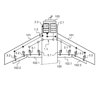
With reference to the figures, an aircraft comprises
a fuselage 100 with respective wings 101 extending from
either side thereof, each wing being fitted in this
example with two flaps 102 (numerical reference 102 is
associated with an identifier .1 or .2 in order to
distinguish between the two flaps; the same applies to
the numerical references for all of the elements
CA 02826455 2013-08-02
WO 2012/117009
PCT/EP2012/053409
4
associated specifically with one or the other of these
flaps). The flaps 102.1 and 102.2 are coupled to a
respective drive device generally referenced 1.1 or 1.2
arranged to move the flaps 102.1 or 102.2 into each of
their positions.
The movements of the flaps 102.1, 102.2 are
controlled by the pilot of the aircraft via controls that
are connected to the central control unit 103, itself
known. The control unit 103 manages the operation of the
various pieces of flight and navigation equipment of the
aircraft. The control unit 103 is connected to the drive
devices 1.1, 1.2 in order to transmit orders to them for
moving the flaps 102.1, 102.2. It is important to
observe that the flaps are controlled in pairs, i.e. both
flaps 102.1 should be moved simultaneously with each
other and both flaps 102.2 should likewise be moved
simultaneously with each other.
Since the drive devices 1.1 and 1.2 are identical to
each other, only one of them is described below and the
numerical references of the corresponding components are
mentioned without their identifiers ".1", or ".2", except
under exceptional circumstances.
Each drive device 1 has a control unit 2 connected
to the control unit 103 and dedicated to controlling the
flaps 102 to which the drive device 1 is coupled.
The control unit 2 is connected to actuators, given
overall reference 3, that are coupled to the
corresponding flaps 102. In the embodiment described,
two actuators 3 are associated with each flap 102.
Each actuator 3 comprises a synchronous alternating
current (AC) motor 4 of the "brushless" type having an
outlet shaft driving a screw jack 5 of the ball- or
roller-screw type. The screw jack 5 has a wormscrew 6
with a nut 7 mounted thereon that is constrained in
translation with a stationary structure and that is
driven in rotation by the outlet shaft of the engine 4
via a stepdown gearbox 8. The screw 6 has one end 9
CA 02826455 2013-08-02
WO 2012/117009
PCT/EP2012/053409
connected to the flap 102 in such a manner as to be
prevented from turning, and it drives the flap on moving
axially.
The screw 6 is fitted with end-of-stroke stops (not
5 shown) that limit the maximum amplitude through which the
screw 6 can be moved.
Each actuator 3 includes at least a load sensor, a
position sensor 10 for sensing the position of the screw
6 (e.g. of the rotary variable differential transformer
(RVDT) type), and a position sensor for sensing the
position of the motor, which sensor is incorporated in
the motor 4 (e.g. of the resolver, code wheel, or optical
coder or other type).
Each actuator 3 has a fail-safe brake, referenced
11, arranged in the absence of electricity to prevent the
screw 6 from moving in translation. The brake 11
operates in friction and is of conventional structure.
The brake 11 has a first plate constrained to rotate with
the nut 7 and a second plate constrained to rotate with
the structure and movable in translation relative to the
first plate between a contact position (dry friction)
against the first plate and a position where it is spaced
apart from the first plate. The second plate is urged
into the contact position by springs and into the spaced-
apart position by a coil that acts, when powered, to
attract the second plate magnetically. The brake 11 is
dimensioned to block the actuator in position when the
motor 4 is not powered, or on instruction from the
control unit, to oppose the motor 4 and stop it in the
event of the motor 4 running away and no longer
responding to the control unit 2.
It can be understood that the control unit 2.1
controls the movement of the flaps 102.1 simultaneously
with each other and that the control unit 2.2 controls
the movement of the flaps 102.2 simultaneously with each
other.
CA 02826455 2013-08-02
WO 2012/117009 PCT/EP2012/053409
6
The operation of a drive device 1 is described
below, which operation is identical both for the drive
device 1.1 of the flaps 102.1 and for the drive device
1.2 of the flaps 102.2.
On being put into operation, the control unit 2
executes a start-up mode including in particular a
routine for determining the positions of the actuators 3,
and a routine for detecting any failure by self-
monitoring.
Once start-up mode has been validated, the control
unit 2 is in normal operation mode and waits for
instructions from the control unit 103.
When the control unit 2 receives an instruction from
the control unit 103 to extend the flaps 102 through a
certain amplitude, the control unit 2 determines the
position that is to be reached and the current that is to
be sent to the motors 4. After the brake 11 has been
unblocked, the electric motors 4 are powered to enable
the motors 4 to perform an acceleration stage, a stage at
constant speed, and then a stage in which the motors 4
decelerate on approaching the position that is to be
reached, until the motors 4 are stopped when said
position is reached. The control unit 2 switches off the
power supply to the motors 4 and simultaneously to the
brake 11, thereby causing the brake 11 to be actuated so
as to block the actuator 3 in position.
The operation of the control unit 2 makes use of two
servo-control loops, one concerning position and the
other concerning current.
All through the three above-described operating
stages, the control unit identifies the slowest motor 4
among the actuators 3 of the flaps 102 and it adapts the
control of the motors 4 to set the control of the motors
4 to match the slowest motor 4. This synchronization of
the actuators 3 serves to avoid any time offset in the
extension of the flaps in the pair of flaps under
consideration or any offset between two portions of a
CA 02826455 2013-08-02
WO 2012/117009
PCT/EP2012/053409
7
given flap that might otherwise not move in parallel,
which might jam the flap. Detecting which motor 4 is the
slowest and adapting the control of the motors thereto
takes place periodically at a frequency that is
appropriate for guaranteeing that any offset is less than
a maximum acceptable offset value.
By way of example, detecting which motor is the
slowest may be performed by comparing the positions of
the motors and/or of the screws at a given instant in
order to identify which actuator is the furthest behind.
Control is adapted by calculating the advance of
each actuator relative to the slowest actuator and in
determining a speed that will enable all of the actuators
to reach the desired position at the same time as the
actuator that is the furthest behind.
Should the delay of the slowest actuator ever exceed
a predetermined threshold, then all of the actuators of
the drive device are stopped.
Throughout the operation of the control unit 2, the
control unit 2 monitors its own operation and the
operation of the actuators 3 in order to detect a failure
as soon as possible.
Various causes of failure and how they can be
detected are listed below:
= jamming of the actuator when the screw remains
stationary and the speed of the motor is zero while its
current consumption increases;
= failure of the angular position sensor of the
motor while its current consumption is normal and
movement of the screw 6 is detected;
= an operating error of the control unit 2 as
detected by a failure detection routine executed by the
control unit 2.
When a failure is detected, execution of a failure
mode is triggered in which the control unit 2 informs the
central control unit 103 of the aircraft that it is no
longer operating and operates the actuators 3 under its
CA 02826455 2013-08-02
WO 2012/117009
PCT/EP2012/053409
8
control so that they are blocked in position. Thus, in
the event of detecting a failure in at least one of the
actuators of one of the flaps on one of the wings, the
actuators of that flap are stopped and also the actuators
of the corresponding flap situated on the other wing,
while the actuators of the other flaps are controlled so
as to move. In a variant, all of the actuators could be
stopped.
Certain failures, in particular those relating to
the control unit 2 can be detected by a failure detection
routine executed by the control unit 103 or by an
external circuit dedicated to monitoring.
Naturally, the invention is not limited to the
implementations described but covers any variant coming
within the ambit of the invention as defined by the
claims.
In particular, the invention is applicable to
aircraft of any type other than airplanes, and in
particular to drones.
The number of actuators per flap is not less than
one and depends, for example, on the length of the flap
and/or on the forces to be developed.
The number of flaps per wing is not less than one
and may be equal to three. The drive device may be
arranged to move more than one flap per wing.
The actuators may present a structure that is
different from that shown, and for example: they may be
purely linear or purely rotary; they may be hydraulic;
they need not have stepdown gearing; ... .
The invention is applicable to other movable
aerodynamic surfaces than wing flaps.